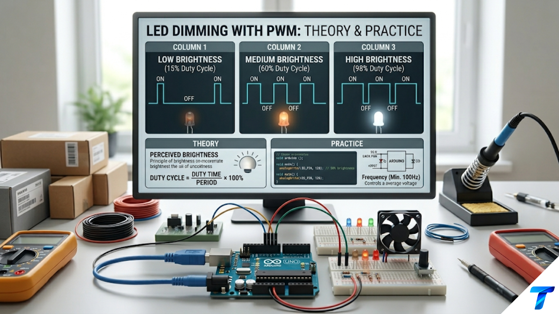
PWM motor speed control varies DC motor speed by rapidly switching the motor supply voltage fully on and off at a fixed frequency, with the duty cycle — the fraction of each cycle the voltage is on — determining the average voltage applied to the motor and therefore its speed. Because the motor winding’s inductance smooths the switching current into a nearly steady flow, the motor responds to the average voltage rather than the switching waveform. PWM achieves high efficiency because the switching transistor dissipates minimal power in either the fully-on or fully-off state — unlike resistive or linear control methods which waste power as heat.
Introduction: Why PWM Is the Standard for Motor Control
A DC motor’s speed is proportional to the voltage applied across it (for a given load). The simplest speed control — a series resistor — works, but wastes enormous power as heat. At half speed, roughly half the supply voltage drops across the motor and half across the resistor. The resistor dissipates as much power as the motor uses. Efficiency: 50% maximum.
Linear transistor control fares no better: biasing a transistor in its active region to drop excess voltage converts that excess power directly to heat in the transistor. Both methods share a fundamental flaw — the energy that does not reach the motor must go somewhere, and that somewhere is waste heat.
PWM eliminates this waste entirely. The switching transistor alternates between two states: fully on (near-zero voltage drop, near-zero power loss) and fully off (zero current, zero power loss). Power loss occurs only during the brief nanosecond transitions between states. All energy entering the circuit either reaches the motor or temporarily stores in the motor’s inductance — none is wasted in the controller. Modern MOSFET-based PWM motor controllers routinely achieve 95–99% efficiency.
Beyond efficiency, PWM offers precise linear speed control, easy microcontroller integration, simple closed-loop control compatibility, and natural extension to bidirectional H-bridge control. These advantages make PWM the universal standard for DC motor control — from hobby gearmotors to industrial servo drives.
This article builds complete practical knowledge for designing PWM motor control circuits: how motors respond electrically to PWM, freewheeling diode requirements, MOSFET selection and gate drive, PWM frequency selection, single-direction and bidirectional H-bridge control, current sensing, and five complete design examples from a simple Arduino motor controller through to closed-loop speed regulation and regenerative braking.
How DC Motors Respond to PWM
The Motor as an Electrical Load
A DC brushed motor is electrically a series combination of three elements:
Winding resistance R: The DC resistance of the copper windings. Typically 2–20Ω for small gearmotors, lower for large motors.
Winding inductance L: Inductive energy storage of the coil. Typically 0.5–10mH for small motors.
Back-EMF source: When rotating, the motor generates a voltage opposing the applied voltage. Back-EMF = K_e × ω, where K_e is the motor’s voltage constant and ω is angular velocity.
The motor’s electrical time constant τ = L/R determines how quickly current responds to voltage changes. For L = 2mH and R = 4Ω: τ = 0.5ms.
Current Behavior Under PWM
During the PWM ON time (switch closed, voltage = V_supply), current rises exponentially toward V_supply/R. During the OFF time (switch open, current freewheels through the diode), current decays exponentially.
If the PWM period T << τ, the current barely changes between transitions. The motor sees an almost constant current equal to V_average/R — just as if a steady DC voltage of D × V_supply had been applied.
If T is comparable to τ, large current ripple results. At very low frequency, the current fully rises and falls each cycle — pulsed operation rather than smooth control.
The smoothness criterion:
f_PWM >> R / (2π × L)For L = 2mH, R = 4Ω: f_PWM >> 318Hz. Even 1kHz provides reasonable smoothing; 10kHz is essentially perfect; 20kHz is industry standard.
Current Ripple Formula
ΔI_ripple = (V_supply × D × (1−D)) / (L_motor × f_PWM)Ripple is worst at D = 50%. For a small gearmotor (L = 1mH, V = 12V, D = 0.5):
| f_PWM | ΔI_ripple | Assessment |
|---|---|---|
| 100Hz | 30A | Unusable — exceeds any motor rating |
| 1kHz | 3A | Very high — poor control |
| 10kHz | 300mA | Moderate — acceptable |
| 20kHz | 150mA | Low — excellent |
| 100kHz | 30mA | Negligible |
Speed-Torque Relationship
The average motor speed is:
ω ≈ (D × V_supply − I × R) / K_eAt no load (I ≈ 0): speed is directly proportional to duty cycle. Under load, the I × R voltage drop reduces speed slightly — the natural speed regulation of a DC motor. Closed-loop control compensates for this.
The Dead Band at Low Duty Cycle
At very low duty cycles, average current is too low to overcome static friction (stiction) and the motor does not rotate. This dead band is typically 5–20% of full duty cycle depending on motor quality and load. In control applications, add a feedforward offset: when non-zero speed is requested, add the minimum duty cycle needed to overcome stiction.
The Freewheeling Diode: Non-Negotiable
Why the Diode Is Essential
When the PWM switch opens during the OFF time, the motor’s winding inductance tries to maintain current flow. An inductor opposes instantaneous current change — if current is forced to zero instantaneously, the voltage spike V = L × dI/dt → ∞.
Without a freewheeling diode, with L = 2mH, I = 2A, switching in 100ns:
V_spike = L × dI/dt = 0.002 × (2 / 100×10⁻⁹) = 40,000VThe transistor’s voltage rating is exceeded by thousands of times. It is destroyed — often dramatically. This is the most common cause of MOSFET failure in motor control circuits built by beginners who omit the diode.
With a freewheeling diode, the inductor current continues flowing through the diode when the switch opens. The voltage is clamped to approximately V_supply + V_f (≈ V_supply + 0.3–0.7V). No destructive spike. The inductor current decays through the motor resistance during the OFF time.
Diode Selection
The freewheeling diode must handle:
Peak current: Must survive the motor’s stall current (3–5× running current) for brief periods.
Reverse voltage: Must block the full supply voltage plus transient margin. Use 20–50% margin — for a 12V supply, use a 30–40V rated diode minimum.
Reverse recovery time: Standard rectifier diodes (1N4007) are slow to turn off when the PWM switch turns on again. During reverse recovery, the diode briefly conducts in reverse, causing current spikes and EMI. For PWM above a few hundred Hz, always use Schottky diodes — their reverse recovery is essentially instantaneous.
Practical choices:
- Up to 1A, 40V: 1N5819 (Schottky, TO-92 or DO-41)
- Up to 3A, 40V: SS34 or 1N5822 (Schottky)
- Up to 3A, 100V: SR360 (Schottky)
- H-bridge MOSFETs: use built-in body diodes, with optional external Schottky in parallel for lower drop
Placement: Mount as close to the motor terminals as physically possible — within a few millimeters in a PCB design. Long wire between diode and motor allows the parasitic inductance to generate spikes between them.
MOSFET Selection and Gate Drive
Logic-Level vs. Standard MOSFETs
Standard power MOSFETs specify R_DS(on) at V_GS = 10V. With a 5V or 3.3V GPIO, they are only partially enhanced — R_DS(on) can be 3–5× higher than the datasheet value, causing excessive heating.
Logic-level MOSFETs specify R_DS(on) at V_GS = 4.5V and are fully enhanced at 5V GPIO drive. For 3.3V systems, check datasheet for V_GS = 2.5V or 3V specification.
Selection table for motor control:
| MOSFET | V_DSS | I_D | R_DS(on) | V_GS spec | Package | Notes |
|---|---|---|---|---|---|---|
| 2N7000 | 60V | 200mA | 5Ω @ 5V | 5V | TO-92 | Signal only |
| AO3400 | 30V | 5.7A | 40mΩ @ 4.5V | 4.5V | SOT-23 | Excellent for strips |
| IRLZ44N | 55V | 47A | 22mΩ @ 5V | 5V | TO-220 | Workhorse, 5V systems |
| FQP30N06L | 60V | 30A | 35mΩ @ 4.5V | 4.5V | TO-220 | Good 3.3V logic-level |
| IRF3205 | 55V | 110A | 8mΩ @ 10V | 10V | TO-220 | High current, needs driver |
Gate Resistor and Pull-Down
Gate resistor (100–470Ω): Limits peak gate current, controls switching speed, reduces high-frequency EMI from fast transitions. Higher resistance = slower switching = more switching losses but less EMI. Start with 100Ω and adjust.
Gate pull-down (10kΩ from gate to source): Holds the gate at 0V when the MCU pin is floating — during power-up, reset, boot sequence, or brownout. Without this, the gate floats to an undefined voltage, potentially leaving the motor on when the system initializes. This is the second most common beginner mistake after omitting the freewheeling diode.
Gate Driver IC
For MOSFETs with total gate charge Q_g > 20nC, or for PWM frequencies above 50kHz, a dedicated gate driver IC provides:
- Peak output current of 2–9A (vs. 20–40mA from a GPIO)
- Faster switching → lower switching losses
- Protection for the MCU GPIO
TC4420 / TC4429 (Microchip): 6A peak, inverting/non-inverting, single supply 4.5–18V. The TC4420 is the go-to gate driver for hobby and professional motor control.
Average gate drive power consumption:
P_gate = Q_g × V_GS × f_PWMFor IRLZ44N (Q_g = 63nC), V_GS = 12V, f = 20kHz:
P_gate = 63×10⁻⁹ × 12 × 20,000 = 15.1mW — negligiblePWM Frequency Selection for Motors
The Three-Way Tradeoff
Current ripple: Decreases inversely with frequency. Higher frequency → smoother current → smoother torque → less motor heating from ripple.
Audible noise: Motor windings vibrate at the switching frequency. Below 20kHz, this is audible (whining, buzzing). Above 20kHz it is inaudible. For any application with human presence, use f_PWM ≥ 20kHz.
Switching losses: Scale linearly with frequency. Every transition dissipates: P_sw = 0.5 × V × I × t_transition × f × 2. Higher frequency → higher losses in the MOSFET.
Recommended Frequencies
1kHz–5kHz: Audible, high ripple. Only for industrial/remote applications where noise is acceptable.
10kHz–20kHz: Approaching inaudible. Good ripple for most motors. Acceptable for many applications.
20kHz (recommended): Silent. Excellent ripple for motors with L ≥ 0.5mH. Manageable switching losses with logic-level MOSFETs and direct GPIO drive. The standard for all hobby and consumer applications.
50kHz–100kHz: Used where very compact filter components or extremely smooth current is needed. Requires gate driver IC and careful MOSFET selection.
Single-Direction PWM Speed Control
The Low-Side Switch Circuit
The simplest PWM motor controller: N-channel MOSFET switches the motor’s return path (between motor negative terminal and ground). Motor positive terminal connects to the supply permanently.
V_supply ────────── Motor (+)
                    Motor (−) ──── MOSFET Drain
Freewheeling diode: anode = Motor(−)/Drain, cathode = V_supply
                                   MOSFET Source ──── GND (common with MCU)
MCU PWM pin ──[100Ω]── MOSFET Gate
MOSFET Gate ──[10kΩ]── GNDWhen MOSFET is on: current flows V_supply → Motor → MOSFET → GND. When MOSFET is off: inductor current freewheels through diode back to motor. Current decays but does not spike.
Complete Arduino Example
// Single-direction motor PWM at 20kHz
// Motor on pin 9, potentiometer on A0

void setup() {
  // Timer 1 phase-correct PWM at 20kHz on pins 9, 10
  TCCR1A = _BV(COM1A1) | _BV(WGM11);
  TCCR1B = _BV(WGM13) | _BV(CS10);  // prescaler=1
  ICR1 = 400;   // 16MHz / (2 × 1 × 400) = 20kHz
  OCR1A = 0;    // Start at 0% duty
  pinMode(9, OUTPUT);
}

void setSpeed(uint8_t percent) {
  // percent 0-100
  // Dead band: below 5% keep off (motor won't spin at < ~5% duty)
  if (percent < 5) {
    OCR1A = 0;
  } else {
    OCR1A = (uint32_t)ICR1 * percent / 100;
  }
}

void loop() {
  int pot = analogRead(A0);                    // 0-1023
  uint8_t speed = map(pot, 0, 1023, 0, 100);  // 0-100%
  setSpeed(speed);
  delay(20);
}Adding Acceleration Limiting
Sudden speed changes from zero to full cause large inrush current spikes. Ramp the duty cycle:
int current_duty = 0;
const int ACCEL_STEP = 2;   // Max change per 20ms loop = 10%/sec

void loop() {
  int target = map(analogRead(A0), 0, 1023, 0, 100);

  // Ramp toward target
  if (target > current_duty + ACCEL_STEP) {
    current_duty += ACCEL_STEP;
  } else if (target < current_duty - ACCEL_STEP) {
    current_duty -= ACCEL_STEP;
  } else {
    current_duty = target;
  }

  setSpeed(current_duty);
  delay(20);
}Bidirectional Control: The H-Bridge
Operating Modes
An H-bridge has four switches (Q1–Q4) arranged around the motor load:
V_supply
    |
   [Q1]              [Q3]
    |                  |
    +──── Motor ────+
    |                  |
   [Q2]              [Q4]
    |                  |
GND GNDForward (Q1 + Q4 on): Current left-to-right through motor. Reverse (Q2 + Q3 on): Current right-to-left. Coast (all off): Motor freewheels freely. Brake (Q2 + Q4 on, or Q1 + Q3 on): Both motor terminals connected to same rail — motor short-circuited, rapid deceleration.
SHOOT-THROUGH — the lethal failure mode: Q1 and Q2 (or Q3 and Q4) simultaneously on connects V_supply directly to GND through two low-resistance switches. Current is limited only by wire resistance — potentially thousands of amps for milliseconds. Both MOSFETs are instantly destroyed, PCB traces may vaporize, and connected components may fail. Every H-bridge design must include hardware deadtime (brief gap between turning one switch off before turning the complementary switch on) and logic interlocks preventing simultaneous activation.
Integrated H-Bridge ICs
For most applications, an integrated H-bridge IC is far preferable to discrete MOSFETs — it handles deadtime, logic interfacing, protection, and packaging in a single part.
| IC | Voltage | Current | R_DS(on) | Notes |
|---|---|---|---|---|
| L293D | 4.5–36V | 0.6A | 70Ω (!) | Avoid — too inefficient |
| DRV8833 | 2.7–10.8V | 1.5A | 360mΩ | Dual H-bridge, excellent |
| DRV8871 | 6.5–45V | 3.6A | 565mΩ | Single H-bridge, 24V capable |
| TB6612FNG | 2.7–13.5V | 1.2A | 500mΩ | Separate PWM pin |
| VNH5019 | 5.5–24V | 12A | 34mΩ | High current, diagnostic output |
The L293D problem: Its 70Ω switch resistance means at 300mA load, V_drop = 21V — more than most supply voltages. At 100mA: 7V drop. It is effectively unusable above about 50mA due to internal losses. The DRV8833 at 360mΩ total (high + low side) is 200× more efficient.
DRV8833 Motor Driver
The DRV8833 contains two complete H-bridges with overcurrent protection and thermal shutdown. Each bridge is controlled by two logic inputs:
| xIN1 | xIN2 | Motor State |
|---|---|---|
| 0 | 0 | Coast |
| 0 | 1 | Forward |
| 1 | 0 | Reverse |
| 1 | 1 | Brake |
PWM speed control: Apply PWM to xIN1, hold xIN2 LOW → forward at variable speed. Or apply PWM to xIN2, hold xIN1 LOW → reverse at variable speed.
Complete bidirectional control:
const int AIN1 = 9, AIN2 = 10;  // Motor A
const int BIN1 = 5, BIN2 = 6;   // Motor B (second motor or unused)
const int STBY = 7;               // LOW = sleep mode

void setup() {
  // 20kHz on Timer 1 (pins 9, 10)
  TCCR1A = _BV(COM1A1) | _BV(COM1B1) | _BV(WGM11);
  TCCR1B = _BV(WGM13) | _BV(CS10);
  ICR1 = 400;

  pinMode(AIN1, OUTPUT); pinMode(AIN2, OUTPUT);
  pinMode(STBY, OUTPUT);
  digitalWrite(STBY, HIGH);  // Enable
}

// speed: -100 (full reverse) to +100 (full forward), 0 = coast
void motorA(int speed) {
  speed = constrain(speed, -100, 100);
  uint16_t duty = (uint32_t)ICR1 * abs(speed) / 100;

  if (speed > 0) {
    OCR1A = duty;  // PWM on AIN1
    OCR1B = 0;     // AIN2 low → forward
  } else if (speed < 0) {
    OCR1A = 0;     // AIN1 low
    OCR1B = duty;  // PWM on AIN2 → reverse
  } else {
    OCR1A = 0; OCR1B = 0;  // Coast
  }
}

void brakeA() {
  OCR1A = ICR1; OCR1B = ICR1;  // Both HIGH → brake
}

void loop() {
  // Ramp forward
  for (int s = 0; s <= 100; s++) { motorA(s); delay(20); }
  delay(500);
  brakeA(); delay(300);

  // Ramp reverse
  for (int s = 0; s >= -100; s--) { motorA(s); delay(20); }
  delay(500);
  brakeA(); delay(300);
}Current Sensing and Motor Protection
Low-Side Current Sensing
A small sense resistor (R_sense) in the low-side return path generates a voltage proportional to motor current:
V_sense = I_motor × R_senseFor R_sense = 0.1Ω and I = 2A: V_sense = 200mV.
Amplify with a dedicated current sense amplifier (INA180: gain options 20, 50, 100 V/V) before reading with the ADC.
Power dissipated in sense resistor at 2A:
P = I² × R = 4 × 0.1 = 400mWUse a 1W or higher rated resistor. For higher currents, use lower R_sense (0.01–0.05Ω) with higher amplifier gain.
Software Overcurrent Protection
const float R_SENSE = 0.1;      // ohms
const float AMP_GAIN = 20.0;    // INA180A1
const float ADC_REF = 5.0;      // volts
const float I_LIMIT = 3.0;      // amps — stall protection
bool fault_latched = false;

float readCurrent() {
  float V_adc = analogRead(A1) * ADC_REF / 1023.0;
  return (V_adc / AMP_GAIN) / R_SENSE;
}

void loop() {
  if (fault_latched) {
    // Stop motor, flash LED — require reset to resume
    analogWrite(9, 0);
    digitalWrite(LED_PIN, (millis() / 500) % 2);
    return;
  }

  if (readCurrent() > I_LIMIT) {
    analogWrite(9, 0);
    fault_latched = true;
    return;
  }

  // Normal control...
}Complete Design Examples
Design Example 1: Arduino + IRLZ44N, 12V Motor, Potentiometer Speed
Application: 12V, 500mA gearmotor (3A stall). Silent 20kHz PWM. Potentiometer speed control.
Key components:
- IRLZ44N (55V, 47A, 22mΩ — way oversized for 500mA, but costs the same as smaller parts and runs perfectly cool)
- 1N5819 Schottky (40V, 1A)
- 100Ω gate resistor, 10kΩ gate pull-down
- 100nF ceramic capacitor across motor terminals
Common ground: Arduino GND and 12V supply GND connected together. Arduino powered by USB. 12V supply powers motor only.
Complete code as shown in the single-direction section above. At 20kHz, zero audible noise, smooth speed control from ~5% to 100% duty cycle.
Design Example 2: 24V Conveyor Belt, DRV8871, Bidirectional
Application: Small industrial conveyor. 24V motor, 2A running / 6A stall. Forward/reverse buttons. Speed via potentiometer. Brake when stopped.
DRV8871: 6.5–45V, 3.6A — adequate for 2A continuous with good thermal headroom.
const int IN1 = 9, IN2 = 10;
const int BTN_F = 2, BTN_R = 3;

void setup() {
  TCCR1A = _BV(COM1A1) | _BV(COM1B1) | _BV(WGM11);
  TCCR1B = _BV(WGM13) | _BV(CS10);
  ICR1 = 400;  // 20kHz
  pinMode(IN1, OUTPUT); pinMode(IN2, OUTPUT);
  pinMode(BTN_F, INPUT_PULLUP);
  pinMode(BTN_R, INPUT_PULLUP);
}

void setMotor(int dir, uint8_t pct) {
  uint16_t d = (uint32_t)ICR1 * pct / 100;
  if (dir > 0)      { OCR1A = d;    OCR1B = 0;    }  // Forward
  else if (dir < 0) { OCR1A = 0;    OCR1B = d;    }  // Reverse
  else              { OCR1A = ICR1; OCR1B = ICR1; }  // Brake
}

void loop() {
  bool fwd = !digitalRead(BTN_F);
  bool rev = !digitalRead(BTN_R);
  uint8_t spd = map(analogRead(A0), 0, 1023, 20, 100);

  if (fwd && !rev)      setMotor(+1, spd);
  else if (rev && !fwd) setMotor(-1, spd);
  else                  setMotor(0, 0);  // Brake

  delay(10);
}Design Example 3: High-Power Motor Driver (48V, 15A, Discrete MOSFETs)
Application: Electric go-kart. 48V brushed motor, 15A continuous, 40A peak. Requires discrete MOSFETs for the current level — no single H-bridge IC handles 15A at 48V economically.
MOSFET selection: IRF3205 (55V, 110A, 8mΩ). At 15A continuous and 50% duty cycle:
P_cond = 225 × 0.008 × 0.5 = 900mW per MOSFETWith heatsink (θ_total = 5°C/W): ΔT = 4.5°C — completely manageable.
Gate driver: TC4420 (6A peak, 6V–18V supply). The IRF3205 Q_g = 170nC — too large for direct GPIO drive.
Switching losses at 20kHz with TC4420:
I_gate ≈ 6A peak → t_sw = Q_gd/I_gate = 71nC/6A ≈ 12ns
P_sw = 0.5 × 48 × 15 × 12ns × 20,000 × 2 = 173mW per deviceFour MOSFETs total: 693mW switching + 3.6W conduction = 4.3W total device loss at 15A.
Bootstrap for high-side gate drive: The two high-side MOSFETs (Q1, Q3) have their sources at the switching node — not ground. Their gates must be driven above their sources (above the switching node). Use IR2104 bootstrap gate driver for each half-bridge leg.
Freewheeling: Body diodes of IRF3205 serve as freewheeling diodes (I_diode rated 110A). No external diodes needed, though external Schottky diodes in parallel reduce forward drop during deadtime.
Design Example 4: Closed-Loop Speed Control with Encoder
Application: Robot wheel drive requiring speed to remain constant under varying loads. 12V motor with quadrature encoder (100 pulses/rev). PI controller, 10ms update interval.
volatile long enc_count = 0;
void encoderISR() { enc_count++; }

long last_count = 0;
float target_rpm = 60.0;
float integral = 0.0;
const float Kp = 0.8, Ki = 0.4, dt = 0.01;

void setup() {
  attachInterrupt(digitalPinToInterrupt(2), encoderISR, RISING);
  TCCR1B = (TCCR1B & 0b11111000) | 0x01;  // 31kHz PWM
  pinMode(9, OUTPUT);
  Serial.begin(115200);
}

void loop() {
  static uint32_t last_ms = 0;
  if (millis() - last_ms >= 10) {
    last_ms = millis();

    long cnt = enc_count;
    float rpm = ((cnt - last_count) / 100.0) * 6000.0; // pulses/10ms→rpm
    last_count = cnt;

    float err = target_rpm - rpm;
    integral += err * dt;
    integral = constrain(integral, -50.0, 50.0);  // Anti-windup

    int pwm = constrain((int)(Kp*err + Ki*integral), 0, 255);
    analogWrite(9, pwm);

    if (Serial.available()) target_rpm = Serial.parseFloat();
  }
}Tuning: Set Ki = 0. Increase Kp until speed oscillates, then halve it. Add Ki gradually until steady-state error disappears without overshoot.
Design Example 5: Regenerative Braking with H-Bridge
Application: Electric go-kart (continuation of Example 3). When braking, the motor acts as a generator — current reverses and flows back into the battery.
How regeneration works: In bipolar PWM, the motor receives average voltage V_avg = (2D − 1) × V_supply (where D = 0.5 is zero, > 0.5 is forward, < 0.5 is reverse). When D drops below the “zero-torque” point (back-EMF / V_supply), the applied voltage is less than the back-EMF. Current reverses — flowing from motor to supply, charging the battery.
Zero-torque duty cycle at speed ω:
D_zero_torque = K_e × ω / V_supplyBelow this duty cycle, regenerative braking occurs automatically in bipolar PWM. No additional circuitry needed — the H-bridge handles current in both directions. The battery must be capable of accepting regenerative current (lithium and lead-acid batteries both can).
// Bipolar PWM: center = 400 (zero torque), range 0-800
// >400 = forward drive, <400 = braking/reverse
void setTorque(int percent) {
  // percent: -100 (max regen) to +100 (full drive)
  uint16_t center = ICR1;  // = 400 for 20kHz with ICR1=400...
  // Actually for bipolar: use separate +/- PWM channels
  // Forward: OCR1A = duty, low side on
  // Regen: reduce duty below zero-torque point

  // Simplified: use sign-magnitude with regen via current sense
  // When commanded speed < actual speed and direction same → apply reverse torque
  int pwm_val = 400 + (percent * 4);  // Map -100..+100 to 0..800
  pwm_val = constrain(pwm_val, 0, 800);
  // Set OCR1A to pwm_val (using ICR1=800 for bipolar full range)
  OCR1A = pwm_val;
}

void loop() {
  int throttle = analogRead(A0);  // 0-1023
  int brake    = analogRead(A1);  // 0-1023

  int torque;
  if (brake > 100) {
    torque = -map(brake, 100, 1023, 0, 80); // Regenerative braking
  } else {
    torque = map(throttle, 0, 1023, 0, 100); // Acceleration
  }
  setTorque(torque);
  delay(5);
}Troubleshooting PWM Motor Control
Motor runs at full speed regardless of PWM duty cycle: Gate pull-down resistor missing. Gate floats HIGH during MCU boot. Add 10kΩ from gate to source. Verify PWM output is working (check with LED or oscilloscope on the PWM pin).
Motor stutters or vibrates at low speed: PWM frequency too low. Motor current fully decays during each OFF cycle. Increase f_PWM to at least 10kHz, ideally 20kHz. Also check if dead band compensation is needed.
MOSFET gets hot: (a) Wrong MOSFET for supply voltage — use logic-level type for 5V/3.3V drive. (b) Switching losses dominate — add gate driver IC, or reduce f_PWM. (c) No heatsink — calculate P_total and add heatsink. (d) Insufficient gate drive voltage — partially enhanced MOSFET has high R_DS(on).
Freewheeling diode gets hot: Normal if conducting large currents, but check duty cycle and motor current. At high currents and low duty cycles, the diode conducts for a large fraction of the cycle. Consider synchronous rectification (turn on the complementary MOSFET instead of using the diode) for better efficiency.
High-pitched noise despite f_PWM > 20kHz: Not motor noise — check for gate drive oscillation (add gate resistor), or power supply ringing (add bulk capacitance near motor). Check that motor and supply ground connections are solid.
Motor runs in only one direction with H-bridge: Logic wiring error. Check truth table for specific IC. Verify both direction inputs actually switch (probe with multimeter). Check that enable/standby pin is HIGH.
Overcurrent protection trips at startup: Motor inrush current on startup exceeds threshold. Implement soft-start: ramp duty cycle from 0 to target over 100–500ms. Alternatively, increase the protection threshold and rely on thermal protection.
Summary
PWM motor speed control achieves high efficiency by switching a MOSFET between fully-on (near-zero losses) and fully-off (zero current) states. The motor’s inductive winding smooths the switching current — the motor responds to average voltage, which is proportional to duty cycle. Linear control by contrast wastes the unconsumed energy as heat.
The freewheeling diode is essential and non-negotiable: without it, inductive kickback destroys the MOSFET when the switch opens. Use Schottky diodes (1N5819, SS34) for fast reverse recovery at any PWM frequency above a few hundred hertz. The gate pull-down resistor (10kΩ) prevents the MOSFET from floating on during system initialization.
PWM frequency of 20kHz is the practical standard for motor control: completely silent (above human hearing), excellent current smoothing for motors with L ≥ 0.5mH, and manageable switching losses for logic-level MOSFETs. Use a gate driver IC (TC4420) for MOSFETs with Q_g > 20nC.
For bidirectional control, integrated H-bridge ICs (DRV8833, DRV8871, TB6612FNG) provide complete, protected motor control in a single package. The L293D should be avoided — its 70Ω switch resistance makes it essentially unusable for real motor loads. Current sensing with a series sense resistor and amplifier enables software overcurrent protection and forms the foundation of torque control and closed-loop current regulation.