A microcontroller is a single integrated circuit that combines a processor (CPU), program memory (Flash), working memory (RAM), and hardware input/output peripherals — analog inputs, digital pins, PWM outputs, and communication buses — all on one chip, making it a complete, self-contained computer in a package smaller than a fingernail. Unlike a general-purpose computer that runs an operating system and handles many tasks simultaneously, a microcontroller typically runs one program continuously, responds to hardware events in predictable, microsecond-level time, and interfaces directly with physical sensors and actuators — making it the right tool for real-time robot control tasks where timing precision matters more than computational power.
Introduction
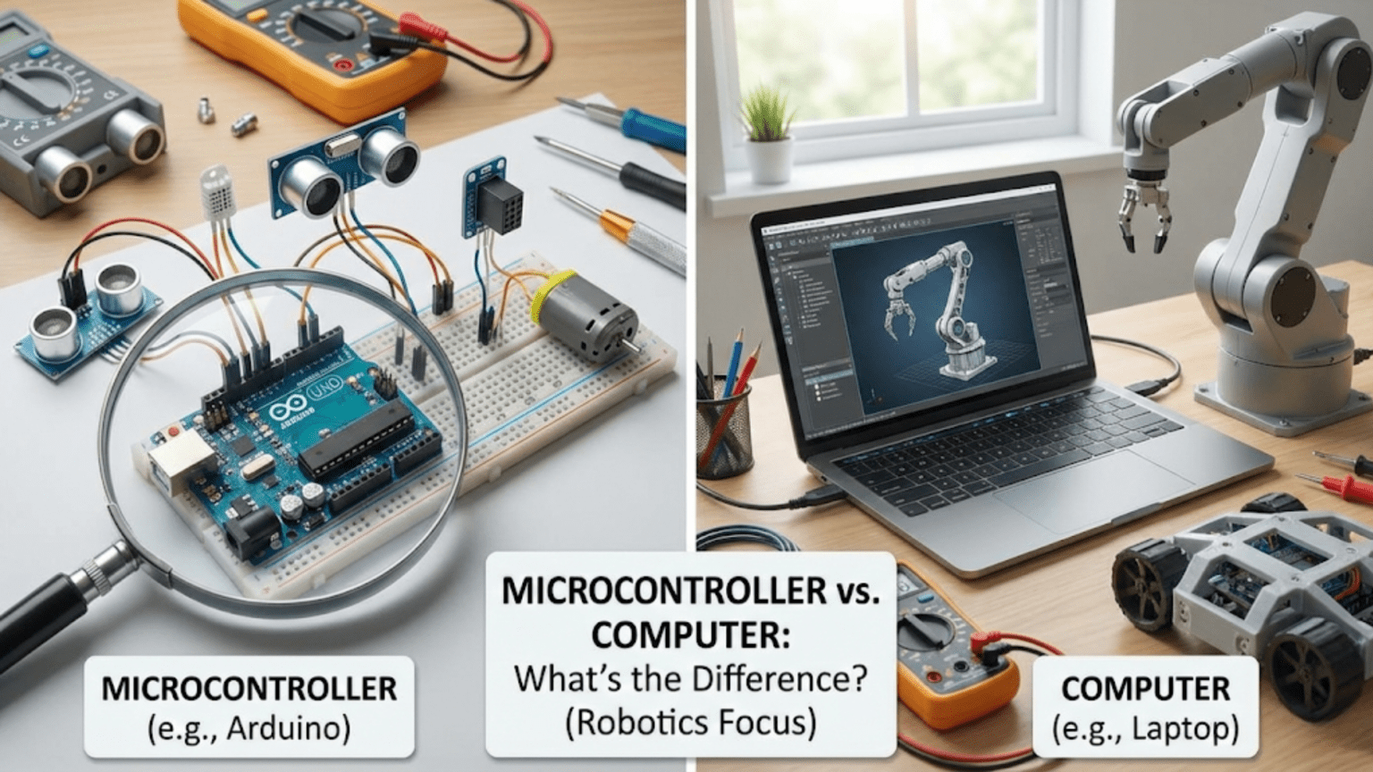
The Arduino sitting at the heart of many beginner robots is often called a “mini computer” in casual descriptions, and it’s easy to understand why — it has a processor, it runs programs, it can communicate over serial connections. But calling a microcontroller a mini computer misses the most important things about it: what makes it different from a computer, why those differences matter enormously for robotics, and why using the right tool — microcontroller versus full computer — for the right task is one of the most important architectural decisions in any robot design.
A robot with only a microcontroller can drive motors with precise timing, read sensors at exact intervals, and respond to hardware events within microseconds. A robot with only a single-board computer running Linux can process camera images, plan paths through a map, and communicate over a network — but may struggle to guarantee that a motor command is executed within 1 millisecond because the operating system is also handling file systems, network packets, and dozens of background processes.
Most capable autonomous robots use both: a microcontroller for real-time hardware control and a computer for high-level computation and decision-making. Understanding what each is, what each does well, and how they complement each other is fundamental to designing robots that work reliably.
What a Microcontroller Actually Is
A microcontroller is a System on Chip (SoC) — a single integrated circuit that integrates everything needed to run a program and interact with the physical world.
The Components Inside One Chip
Open the datasheet for an ATmega328P (the chip on an Arduino Uno) and you’ll find these components integrated on a single piece of silicon roughly 7mm × 7mm:
Central Processing Unit (CPU): The core execution engine. The ATmega328P uses an 8-bit AVR RISC CPU that executes most instructions in a single clock cycle. At 16MHz, it can execute up to 16 million instructions per second. This is far less powerful than a modern PC processor but more than enough for reading sensors, computing control loops, and driving motors.
Flash Memory (Program Storage): 32KB of non-volatile Flash memory stores the program — the compiled machine code that defines what the microcontroller does. Flash retains its contents when power is removed, which is why the Arduino remembers its program after being powered off and on. When you upload a sketch from the Arduino IDE, you’re writing compiled code into this Flash.
SRAM (Working Memory): 2KB of static RAM holds variables, the call stack, and runtime data while the program runs. 2KB sounds tiny — and it is. A string of 2,000 characters would fill it completely. This constraint forces careful memory management in microcontroller programming, a discipline that doesn’t exist in desktop software development where gigabytes of RAM are available.
EEPROM: 1KB of electrically erasable programmable read-only memory stores data that needs to survive power cycles but isn’t the program itself — calibration values, configuration settings, accumulated sensor readings. Unlike Flash (which wears out after about 10,000 write cycles), EEPROM is rated for 100,000 write cycles per byte.
Hardware Peripherals: This is what truly distinguishes a microcontroller from a bare processor. The ATmega328P includes, on the same chip:
- 14 digital I/O pins (configurable as input or output)
- 6 analog input pins (10-bit ADC, 0–5V range)
- 6 PWM output channels (for motor speed, LED brightness, servo position)
- UART (serial communication)
- SPI (high-speed synchronous serial)
- I2C (two-wire sensor bus)
- Hardware timers and counters
- Watchdog timer
- Internal oscillator (though an external crystal provides better accuracy)
All of these peripherals operate independently of the CPU — when the hardware UART receives a byte, it stores it in a hardware buffer and optionally interrupts the CPU to notify it. The CPU doesn’t have to constantly check whether a byte has arrived; the hardware does it automatically.
ATmega328P at a glance:

┌─────────────────────────────────────────┐
│            ATmega328P                   │
│                                         │
│  ┌──────────┐  ┌──────────┐             │
│  │   CPU    │  │  Flash   │             │
│  │ 8-bit    │  │  32 KB   │             │
│  │ AVR RISC │  │ (program)│             │
│  └──────────┘  └──────────┘             │
│  ┌──────────┐  ┌──────────┐             │
│  │   SRAM   │  │  EEPROM  │             │
│  │   2 KB   │  │   1 KB   │             │
│  │(variables│  │(settings)│             │
│  └──────────┘  └──────────┘             │
│                                         │
│  Peripherals: ADC, UART, SPI, I2C,      │
│  Timers, PWM, GPIO, Watchdog            │
│                                         │
│  Package: 28-pin DIP or 32-pad QFP      │
│  Supply: 1.8–5.5V                       │
│  Current: 0.3mA idle, 12mA active       │
└─────────────────────────────────────────┘
What a Microcontroller Does NOT Have
Just as important as what’s on the chip is what’s missing:
No operating system. A microcontroller runs bare metal — your code runs directly on the hardware with no OS layer in between. There is no file system, no memory manager, no process scheduler, no device driver framework. The Arduino’s setup() function runs once, then loop() runs repeatedly, forever. That’s the entire execution model.
No display, keyboard, or storage. A microcontroller has no way to show information or accept user input on its own — those require external peripherals (LCD module, button, SD card module).
Minimal networking. A bare ATmega328P has no WiFi, no Ethernet, no Bluetooth. Adding networking requires external modules (ESP8266 over UART, W5500 SPI Ethernet shield, etc.).
No dynamic memory allocation. While C’s malloc() is technically available in AVR code, using it on a 2KB SRAM microcontroller is asking for trouble — memory fragmentation will exhaust the heap unpredictably. Best practice: allocate everything statically at compile time.
What a General-Purpose Computer Is (and Why It’s Different)
A Raspberry Pi, Jetson Nano, or BeagleBone Black runs a full Linux operating system. Understanding how this differs from a microcontroller illuminates why each is appropriate for different tasks.
The OS Layer: Power and Overhead
The Linux kernel running on a Raspberry Pi manages:
- Virtual memory (maps physical RAM to process address spaces)
- Scheduling (switches between processes, typically every 1–10ms)
- Device drivers (abstracts hardware into standard interfaces)
- File systems (manages SD card storage)
- Network stack (handles WiFi, Ethernet, TCP/IP, DNS)
- Security (user permissions, process isolation)
This OS layer provides enormous capability: you can run Python scripts, process camera frames with OpenCV, communicate over a network, stream sensor data to a database, and update software over WiFi. The operating system makes all of this possible.
But the OS layer also introduces non-determinism — the inability to guarantee exactly when a piece of code will run. When a Linux process calls time.sleep(0.001) asking to wake up in 1 millisecond, the OS may actually wake it up in 1ms, 2ms, 5ms, or 15ms, depending on what else the scheduler is doing. Most of the time it’s close to 1ms. Occasionally it isn’t.
For robotics tasks where timing precision matters — reading a quadrature encoder every 100µs, sending a PWM signal with exactly 1500µs pulse width to a servo, responding to a limit switch within 500µs — this non-determinism is unacceptable. A 5ms scheduling delay in an encoder reading routine causes position errors. A 2ms variation in servo pulse width causes jitter.
Processing Power and Connectivity
Where computers dramatically outperform microcontrollers:
Raspberry Pi 4 vs. Arduino Uno:

Raspberry Pi 4 (2GB):
  CPU: 4× ARM Cortex-A72, 64-bit, 1.5GHz
  RAM: 2GB LPDDR4
  Storage: SD card (32GB+)
  GPU: VideoCore VI (capable of real-time image processing)
  Connectivity: WiFi, Bluetooth, 2× USB 3.0, Gigabit Ethernet, HDMI
  OS: Raspberry Pi OS (Linux-based)
  Power: ~4W typical
  Cost: ~$35–55

Arduino Uno:
  CPU: 1× AVR ATmega328P, 8-bit, 16MHz
  RAM: 2KB SRAM
  Storage: 32KB Flash (program), 1KB EEPROM
  GPU: None
  Connectivity: UART (via USB), SPI, I2C
  OS: None (bare metal)
  Power: ~0.25W typical
  Cost: ~$4–25 depending on source

Processing ratio: Pi is approximately 3,000× more powerful by raw throughput
Memory ratio: Pi has approximately 1,000,000× more RAMA Raspberry Pi can process a 640×480 camera frame in Python in 30ms. An Arduino Uno cannot process a camera at all — it lacks the RAM to store even a single frame (a 640×480 grayscale image requires 307,200 bytes; the Uno has 2,048 bytes of SRAM).
Real-Time Control: Where Microcontrollers Excel
The defining advantage of a microcontroller is deterministic, real-time behavior — the ability to execute actions at precisely specified times, respond to hardware events within microseconds, and maintain consistent timing regardless of what else is “happening” (because nothing else is happening — there’s only one program).
What Real-Time Means in Practice
Motor control: A PID control loop for a DC motor typically needs to run every 5–20ms with consistent timing. On a microcontroller, a hardware timer interrupt fires exactly every 10ms and the control code runs. On a Linux single-board computer, the control loop might run in 8ms, then 12ms, then 9ms, then 15ms (scheduler preemption). The varying sample rate degrades PID performance, causing oscillation or poor tracking.
Encoder reading: Quadrature encoders generate pulses at rates of hundreds to thousands of pulses per second at high motor speeds. Each pulse transition must be detected and counted accurately. On a microcontroller, hardware interrupt pins capture every edge in real time. On a Raspberry Pi, Python code polling a GPIO pin can miss pulses if the scheduler preempts the polling thread for even a few milliseconds.
PWM generation: Servo motors and some motor drivers require PWM signals with pulse widths accurate to tens of microseconds. Hardware PWM on a microcontroller generates these signals from a hardware timer, completely independent of what code is executing. Software-generated PWM on a Linux system (toggling a GPIO pin from code) has significant timing variation due to scheduler jitter.
Safety-critical response: If a robot’s limit switch is hit, the motor must stop within milliseconds. On a microcontroller, a hardware interrupt attached to the limit switch pin fires within microseconds of the pin changing state, regardless of what the CPU is executing. The interrupt service routine can immediately zero the motor PWM. On a Linux system, interrupt latency for GPIO is typically 10–100µs with PREEMPT_RT patches, but can be milliseconds with standard kernels.
// Real-time encoder reading on Arduino — hardware interrupts
// Counts encoder pulses with hardware-guaranteed timing

volatile long encoderCount = 0;

// Interrupt Service Routine — called instantly when encoder pin changes
void ICACHE_RAM_ATTR encoderISR() {
  if (digitalRead(ENCODER_B_PIN) == HIGH) {
    encoderCount++;
  } else {
    encoderCount--;
  }
}

void setup() {
  pinMode(ENCODER_A_PIN, INPUT_PULLUP);
  pinMode(ENCODER_B_PIN, INPUT_PULLUP);
  // Attach interrupt — fires on EVERY rising and falling edge of pin A
  attachInterrupt(digitalPinToInterrupt(ENCODER_A_PIN),
                  encoderISR, CHANGE);
}

void loop() {
  // encoderCount is updated in real time by the ISR
  // No polling delay, no missed pulses
  Serial.println(encoderCount);
  delay(100);
}This interrupt-driven encoder reading guarantees that every single pulse is counted, regardless of what the loop() function is doing. The hardware interrupt mechanism is the microcontroller’s real-time superpower.
The Microcontroller Family: Beyond Arduino
Arduino is the entry point for most robotics builders, but it represents only a small fraction of the microcontroller ecosystem. Understanding the broader landscape helps you select the right chip as your projects grow.
AVR Family (ATmega, ATtiny)
The Arduino Uno, Nano, and Mega use Atmel (now Microchip) AVR microcontrollers. The ATmega328P (Uno) and ATmega2560 (Mega) are reliable workhorses for beginner and intermediate robotics. The ATtiny series (ATtiny85, ATtiny84) are extremely small and low-power — used in applications where the full Arduino is too large or uses too much power.
Strengths: Mature ecosystem, extensive documentation, enormous community, breadth of compatible libraries. Weaknesses: 8-bit architecture, limited RAM (2KB on Uno), 16MHz maximum speed.
ARM Cortex-M Family
Most modern microcontrollers use ARM Cortex-M cores — 32-bit processors with vastly more processing power than AVR:
ARM Cortex-M comparison:

Cortex-M0/M0+:  32-bit, ~48MHz, ~16KB RAM, ~64KB Flash
               Used in: Arduino Zero, many Adafruit boards
               Step up from AVR with 32-bit math, slightly more memory

Cortex-M3:     32-bit, ~72MHz, ~64KB RAM, ~128KB Flash
               Used in: STM32F1 series, many industrial MCUs
               Significant performance increase; hardware multiply/divide

Cortex-M4:     32-bit, ~168MHz, 192KB–1MB RAM, ~1MB Flash
               Usually includes hardware FPU (floating-point unit)
               Used in: STM32F4, Teensy 3.x, many motor controllers
               Capable of serious signal processing, fast control loops

Cortex-M7:     32-bit, ~480MHz, ~1MB RAM, ~2MB Flash, DSP extensions
               Used in: Teensy 4.x, STM32H7
Approaches microprocessor performance in a microcontrollerThe STM32 family (STMicroelectronics) is particularly popular in advanced robotics — motor controllers, flight controllers for drones (Betaflight runs on STM32), and robot joint controllers often use STM32F4 or STM32H7 chips for their combination of real-time performance and significant processing power.
ESP32 and ESP8266: Microcontrollers with WiFi
The ESP8266 and ESP32 (Espressif Systems) are microcontrollers with integrated WiFi (and Bluetooth on the ESP32), making them popular for connected robots, IoT applications, and remote-controlled projects.
ESP32 specifications:
  CPU: Dual-core Xtensa LX6, 32-bit, 240MHz
  RAM: 520KB SRAM (+ PSRAM option up to 16MB)
  Flash: 4–16MB (external SPI Flash)
  WiFi: 802.11 b/g/n (2.4GHz)
  Bluetooth: 4.2 + BLE
  GPIO: 34 pins, 18 ADC channels, 16 PWM channels
  Peripherals: I2C, SPI, UART, I2S, DAC, touch inputs, Hall effect sensor
  Cost: ~$3–8 module

Compared to Arduino Uno:
  15× faster clock speed
  260× more RAM
  Built-in WiFi and Bluetooth
  More pins and peripherals
Still a microcontroller: no OS, real-time behavior, direct hardware accessThe ESP32 is now the dominant choice for robotics projects requiring network connectivity. Its dual-core architecture even allows separating communication tasks (WiFi handling on one core) from control tasks (sensor reading and motor control on the other), providing better real-time performance than single-core WiFi microcontrollers.
RP2040: Raspberry Pi’s Microcontroller
The RP2040, released by Raspberry Pi in 2021, powers the Raspberry Pi Pico and is notable for an unusual feature: Programmable I/O (PIO) state machines. These are tiny, independently-running processors dedicated to I/O operations, capable of implementing custom protocols (WS2812B LED driving, custom encoder interfaces, unusual sensor protocols) entirely in hardware without consuming CPU time.
RP2040 specifications:
  CPU: Dual-core ARM Cortex-M0+, 133MHz
  RAM: 264KB SRAM
  Flash: External (2MB on Pico board)
  PIO: 2 PIO blocks, 4 state machines each
  USB: Native USB device/host
  GPIO: 30 pins
Cost: ~$1 (chip), ~$4 (Pico board)The PIO system makes the RP2040 particularly interesting for robotics applications involving unusual hardware interfaces, custom protocols, or precise signal generation — tasks that would require complex interrupt handling or dedicated hardware on other platforms.
Microcontroller vs. Computer: Choosing for Your Robot
The practical question is never “which is better?” — it’s “which is right for this part of this robot?” Many capable robots use both.
Tasks That Belong on a Microcontroller
Real-time motor control (PID loops, PWM generation)       → Microcontroller
Encoder reading (high-speed, interrupt-driven)            → Microcontroller
Servo control (precise PWM timing)                        → Microcontroller
Safety-critical responses (limit switches, emergency stop)→ Microcontroller
Low-level sensor interfacing (I2C, SPI sensors)           → Microcontroller
Battery monitoring and protection                         → Microcontroller
Status LEDs and indicators                                → Microcontroller
Simple autonomous behaviors (line following, obstacle avoid)→ Microcontroller
RC receiver decoding → MicrocontrollerTasks That Belong on a Computer (SBC)
Computer vision (camera processing, object detection)     → Computer (SBC)
Deep learning inference (neural networks)                 → Computer (SBC)
Simultaneous Localization and Mapping (SLAM)              → Computer (SBC)
Path planning in complex environments                     → Computer (SBC)
High-level decision making and state machines             → Computer (SBC)
Network communication (ROS, MQTT, REST APIs)              → Computer (SBC)
Natural language processing                               → Computer (SBC)
Data logging to files                                     → Computer (SBC)
Web interface for robot control → Computer (SBC)The Combined Architecture: Best of Both Worlds
Most capable autonomous robots use a two-tier architecture:
┌─────────────────────────────────────────────────────┐
│        High-Level Computer (Raspberry Pi)           │
│                                                     │
│  Camera → Object Detection → Path Planning          │
│  ROS nodes, high-level behaviors, network           │
│  Sends commands: "set motor speed to 0.3 m/s"       │
│  Receives data: "current position, sensor readings" │
│                                                     │
│  Communication: UART serial, USB, I2C, ROS Serial   │
└──────────────────────┬──────────────────────────────┘
                       │ Commands (high-level)
                       │ Telemetry (sensor data)
┌──────────────────────▼──────────────────────────────┐
│            Real-Time Microcontroller (Arduino/STM32)│
│                                                     │
│  Motor control (PID loops, PWM)                     │
│  Encoder reading (hardware interrupts)              │
│  IMU data acquisition                               │
│  Battery monitoring                                 │
│  Safety limits (limit switches, overcurrent)        │
│  Directly controls: motors, servos, actuators       │
│                                                     │
└─────────────────────────────────────────────────────┘
In this architecture, the Raspberry Pi doesn’t know how to spin a motor — it issues a command like “set left motor speed to 150 RPM” over serial. The Arduino receives this command, calculates the required PWM, runs a PID control loop with encoder feedback, and executes the motion with real-time precision. The Pi doesn’t know or care about the PID — it just says where to go. The Arduino doesn’t know or care about the path plan — it just executes the motion command it receives.
This separation of concerns is why robots like the TurtleBot, most ROS-based platforms, and competition robots use exactly this architecture. The microcontroller handles real-time hardware interaction. The computer handles everything that requires significant computation or communication.
Programming Models: How They Differ
The programming model for a microcontroller differs fundamentally from computer programming, and understanding this shapes how you write robot code effectively.
The Superloop
The most basic microcontroller program structure is the superloop — a setup() function that runs once, followed by a loop() function that runs forever:
void setup() {
  // Runs once: initialize peripherals, configure pins, set up timers
  Serial.begin(9600);
  pinMode(LED_PIN, OUTPUT);
  Wire.begin();
  imu.initialize();
}

void loop() {
  // Runs repeatedly, forever, as fast as the MCU can execute
  // No OS, no scheduler — just this loop, cycling continuously

  readSensors();
  updateControlLoop();
  driveMotors();
  checkSafety();
  sendTelemetry();
  // Then back to readSensors()...
}The cycle time of this loop is determined by how long each function takes to execute. If readSensors() takes 5ms and updateControlLoop() takes 2ms and everything else takes 1ms, the total loop time is about 8ms — meaning the control loop runs at approximately 125Hz.
Interrupt-Driven Programming
For tasks that must happen at exact times or in response to hardware events, interrupts break out of the superloop:
// Hardware timer interrupt — fires every 10ms exactly
// Completely independent of loop() execution time
ISR(TIMER1_COMPA_vect) {
  // This code runs every 10ms, guaranteed
  // Even if loop() is blocked doing Serial.print()
  encoderCount += readEncoderDelta();
  pidOutput = computePID(targetSpeed, encoderCount);
  analogWrite(MOTOR_PWM, pidOutput);
}

void loop() {
  // Lower-priority tasks that don't need exact timing
  if (Serial.available()) {
    String command = Serial.readStringUntil('\n');
    parseCommand(command);
  }
  sendTelemetry();   // Doesn't matter exactly when this runs
  delay(100);        // Slow this down — precise timing is in the ISR
}This model — real-time tasks in interrupt service routines, non-time-critical tasks in the main loop — is the foundation of professional microcontroller programming for robotics.
Event-Driven State Machines
For more complex robot behaviors, a state machine structure handles the logic cleanly without blocking the control loop:
// Non-blocking state machine — never uses delay()
// Each state has entry actions, ongoing actions, and exit conditions

enum RobotState {
  STATE_IDLE,
  STATE_MOVING_FORWARD,
  STATE_AVOIDING_OBSTACLE,
  STATE_TURNING
};

RobotState currentState = STATE_IDLE;
unsigned long stateStartTime = 0;

void updateStateMachine() {
  switch (currentState) {
    case STATE_IDLE:
      stopMotors();
      if (startCommandReceived) {
        transitionTo(STATE_MOVING_FORWARD);
      }
      break;

    case STATE_MOVING_FORWARD:
      driveForward(0.3);  // 30% speed
      if (obstacleDetected()) {
        transitionTo(STATE_AVOIDING_OBSTACLE);
      }
      break;

    case STATE_AVOIDING_OBSTACLE:
      stopMotors();
      if (millis() - stateStartTime > 500) {  // Wait 500ms
        transitionTo(STATE_TURNING);
      }
      break;

    case STATE_TURNING:
      turnRight();
      if (millis() - stateStartTime > 800) {  // Turn for 800ms
        transitionTo(STATE_MOVING_FORWARD);
      }
      break;
  }
}

void transitionTo(RobotState newState) {
  currentState = newState;
  stateStartTime = millis();
}

void loop() {
  updateStateMachine();  // Called every loop iteration — never blocks
  readSensors();
  updateMotors();
}This non-blocking approach is essential for microcontroller robotics — delay() halts everything, including sensor reads and safety checks. State machines with millis()-based timing allow complex behaviors without ever blocking the main loop.
Summary
A microcontroller is a complete computing system on a single chip: processor, program memory, working memory, and hardware peripherals all integrated together, running a single program directly on the hardware without an operating system. This architecture makes microcontrollers the right tool for real-time robot control — tasks where timing precision, deterministic response to hardware events, and direct interaction with sensors and actuators matter more than raw processing power.
The contrast with general-purpose computers (Raspberry Pi, Jetson, PC) is stark and important: computers provide enormous processing power, operating systems, networking, and the ability to run complex software — but at the cost of timing determinism. An operating system’s scheduler makes no guarantees about when a specific piece of code will run, making computers unsuitable for directly driving motors with microsecond-level timing precision.
The right answer for most capable robots is both: a microcontroller handling real-time hardware interaction with guaranteed timing, and a computer handling high-level computation, vision processing, and decision-making. The microcontroller is the robot’s nervous system, responding instantly to the physical world. The computer is the robot’s brain, planning what to do next. Understanding this architecture — when to use each, how they communicate, and what belongs in each layer — is the foundation of designing robots that are both capable and reliable.
The next article explores one of the most fundamental aspects of microcontroller performance: clock speed and how it determines the microcontroller’s ability to execute instructions, generate precise timing signals, and sample sensors at required rates.
Choosing Your First Microcontroller: A Practical Guide
With dozens of microcontroller boards available, beginners face a genuinely confusing choice. This guide narrows it down to the most relevant options for robotics and explains which fits which situation.
Arduino Uno / Nano: The Learning Standard
The Arduino Uno and Nano remain the best choice for first-time robotics builders despite their age, for reasons that have nothing to do with raw performance:
Ecosystem depth: Thousands of libraries cover virtually every sensor, actuator, and module a beginner will encounter. The HC-SR04 ultrasonic library, the Servo library, the Wire library for I2C — all are mature, well-documented, and work reliably on these boards.
Community size: When something goes wrong (and it will), millions of forum posts, tutorials, and answered questions exist for Arduino-specific problems. The probability that your exact problem has been solved and documented by someone else is very high.
IDE accessibility: The Arduino IDE is genuinely easy to install and use. Uploading code requires one USB cable and one button click.
Limitations to know: 2KB RAM is the primary constraint. Any project involving string manipulation, JSON parsing, or large data arrays will hit this limit quickly. When you find yourself fighting memory, it’s time to move up.
When Arduino Uno/Nano is the right choice:
✓ First robotics project
✓ Simple sensor → actuator control
✓ Learning the fundamentals
✓ Any project where RAM < 2KB is sufficient
✓ Projects using common Arduino-compatible modules and shields

When to look elsewhere:
✗ Need WiFi/Bluetooth
✗ Processing large amounts of data
✗ Need more than ~12 I/O pins (Nano) or need specific peripherals
✗ Speed-critical signal processingArduino Mega: More Pins and Memory
The Mega 2560 uses the ATmega2560, which provides:
- 54 digital I/O pins (15 PWM)
- 16 analog inputs
- 8KB SRAM (4× the Uno)
- 256KB Flash (8× the Uno)
- 4 hardware UART ports
For robots with many sensors, many motors, or complex code that strains the Uno’s 2KB SRAM, the Mega is the natural upgrade while staying in the familiar Arduino ecosystem.
ESP32: WiFi, More Power, Still Beginner-Friendly
The ESP32 has largely superseded the Arduino Uno for projects requiring network connectivity, and has become popular even for offline projects due to its dramatically greater resources (520KB RAM, dual-core 240MHz) at comparable or lower cost:
ESP32 vs. Arduino Uno for beginners:

Advantages of ESP32:
  + Built-in WiFi and Bluetooth
  + 260× more RAM
  + 15× faster
  + More GPIO, more ADC channels, more peripherals
  + Compatible with Arduino IDE (install ESP32 board support)
  + Often costs less than genuine Arduino Uno

Disadvantages for beginners:
  - 3.3V logic (not 5V like Uno) — some 5V modules need level shifting
  - ESP32-specific quirks in timing functions and pin behavior
  - Some Arduino libraries don't support ESP32
  - More complex power considerations

Recommendation: If your project requires WiFi or BLE, start with ESP32.
If you just need straightforward sensor/actuator control with no networking,
Arduino Uno/Nano is simpler to start with.Teensy: When Performance Matters
The Teensy series (4.0, 4.1 by PJRC) offers Arduino IDE compatibility with ARM Cortex-M7 performance:
- Teensy 4.1: 600MHz ARM Cortex-M7, 1MB RAM, 8MB Flash
- Full hardware floating-point unit
- USB host capability
- Arduino IDE compatible with Teensyduino add-on
For robotics applications requiring fast DSP (digital signal processing), high-frequency sensor sampling, or complex real-time control algorithms, the Teensy 4.x offers microcontroller-class real-time behavior with processing power approaching a small computer.
Raspberry Pi Pico: Low Cost, Unusual Features
The Raspberry Pi Pico (RP2040) at ~$4 offers dual-core Cortex-M0+ performance with the unusual PIO system that can implement custom hardware protocols. Its Python support (MicroPython, CircuitPython) makes it accessible to Python programmers learning microcontroller development without learning C/C++.
How Microcontrollers Communicate with Computers
In a two-tier robot architecture, the microcontroller and the companion computer must exchange data reliably. Several standard protocols handle this communication.
UART Serial (Most Common)
The Arduino’s Serial interface and the Raspberry Pi’s /dev/ttyAMA0 (or /dev/ttyUSB0 for USB) provide bidirectional text or binary communication. This is the most common microcontroller-to-computer link in hobby robotics:
// Arduino side: send sensor data, receive commands
void loop() {
  // Send IMU and encoder data every 20ms
  static unsigned long lastSend = 0;
  if (millis() - lastSend >= 20) {
    Serial.print("ENC:");
    Serial.print(encoderLeft);
    Serial.print(",");
    Serial.print(encoderRight);
    Serial.print(";IMU:");
    Serial.print(imuYaw, 2);
    Serial.println();
    lastSend = millis();
  }

  // Receive motor commands from Pi
  if (Serial.available()) {
    String line = Serial.readStringUntil('\n');
    if (line.startsWith("MOT:")) {
      // Parse "MOT:150,150" into left/right speeds
      int comma = line.indexOf(',');
      int leftSpeed  = line.substring(4, comma).toInt();
      int rightSpeed = line.substring(comma + 1).toInt();
      setMotorSpeeds(leftSpeed, rightSpeed);
    }
  }
}# Raspberry Pi side: receive sensor data, send commands
import serial
import time
ser = serial.Serial('/dev/ttyUSB0', 9600, timeout=0.1)
def send_motor_command(left_speed, right_speed):
cmd = f"MOT:{left_speed},{right_speed}\n"
ser.write(cmd.encode())
def read_sensor_data():
line = ser.readline().decode().strip()
if line.startswith("ENC:"):
# Parse "ENC:1024,1022;IMU:45.32"
parts = line.split(';')
enc_parts = parts[0][4:].split(',')
enc_left = int(enc_parts[0])
enc_right = int(enc_parts[1])
return enc_left, enc_right
return None
# Main control loop
while True:
data = read_sensor_data()
if data:
enc_left, enc_right = data
# High-level decision making based on sensor data
left_cmd, right_cmd = compute_navigation_command(enc_left, enc_right)
send_motor_command(left_cmd, right_cmd)
time.sleep(0.02) # 50Hz command rateROS Serial (rosserial)
For robots using the Robot Operating System (ROS), the rosserial library allows an Arduino to appear as a ROS node, publishing and subscribing to ROS topics over a serial connection. This is the standard integration method for ROS-based robots with Arduino hardware interfaces.
I2C Controller/Peripheral
A Raspberry Pi can act as an I2C master and communicate with an Arduino configured as an I2C slave. This is useful when the two boards are co-located on the robot and the I2C bus speed and simplicity is preferable to UART.
Understanding these communication pathways — and choosing the right one for your architecture — is as important as understanding the microcontroller itself. The microcontroller is most powerful when it’s tightly integrated with the right companion hardware, whether that’s a simple battery and a few sensors or a full Linux computer coordinating its activities.
Common Misconceptions About Microcontrollers
A few persistent misconceptions cause beginners to choose the wrong tool or misuse the right one:
“The Arduino is too slow for serious robotics”
This conflates processing power with suitability. The Arduino’s 16MHz AVR is absolutely sufficient for:
- Running PID control loops at 100–500Hz
- Reading 5–10 sensors per loop iteration
- Controlling 4–8 motors simultaneously
- Decoding quadrature encoders via interrupts
- Handling I2C and SPI communication with multiple devices
Where it falls short is computationally intensive tasks: matrix operations for sensor fusion, image processing, path planning in large maps. For those tasks, use a companion computer — not a faster microcontroller, which still won’t process a camera image.
The correct question isn’t “is the Arduino fast enough?” but “is this the right tool for this specific task?”
“More RAM and MHz always means a better microcontroller”
Bigger specs mean better only if your application actually needs them. An ATtiny85 with 512 bytes of RAM and 8KB of Flash, running at 8MHz, is the perfect microcontroller for a robot’s battery level indicator — it does exactly what’s needed using microamp quiescent current, fits in a tiny space, and costs less than a dollar. Using an ESP32 for the same task wastes resources and power.
Match specifications to requirements. The “best” microcontroller for a task is the simplest one that meets the requirements, not the most powerful one available.
“Microcontrollers and microprocessors are the same thing”
A microprocessor is just the CPU — it needs external RAM, external Flash, external I/O controllers to function. A microcontroller integrates all of these on one chip. The Raspberry Pi uses a microprocessor (ARM Cortex-A72 CPU) paired with external LPDDR4 RAM and an SD card for storage. The Arduino uses a microcontroller (ATmega328P) with everything on one chip.
This distinction matters practically: a microprocessor system needs an operating system to manage its external memory and peripherals, making it non-deterministic. A microcontroller system runs bare metal with everything on-chip, enabling deterministic real-time behavior.
“The ESP32 is a replacement for a Raspberry Pi”
Despite being much more powerful than an Arduino, the ESP32 is still a microcontroller — it runs bare metal (or FreeRTOS), has limited RAM (520KB), and cannot run Linux. It cannot process camera images with OpenCV, run ROS, or host a web application with a database backend.
The ESP32 fills the gap between a simple Arduino and a full Linux SBC: for IoT applications, remote sensor nodes, connected actuators, and robots that need WiFi without full computer complexity, it’s ideal. For high-level computation, vision, and planning, it is not a replacement for a Raspberry Pi.
Your First Microcontroller Program: Understanding What Runs Where
To make everything concrete, here’s a complete, working Arduino program that demonstrates the key microcontroller concepts discussed in this article — hardware peripherals, interrupts, timing, and serial communication:
/*
 * Microcontroller Demonstration Sketch
 * Demonstrates: interrupt-driven encoder, hardware PWM, serial communication,
 *               timing with millis(), and basic state logic
 * Hardware: Arduino Uno, one DC motor with encoder, one LED
 */

// ─── Pin definitions ──────────────────────────────────────────────
const int MOTOR_PWM_PIN   = 9;   // Hardware PWM output (Timer 1)
const int MOTOR_DIR_PIN   = 8;   // Motor direction
const int ENCODER_A_PIN   = 2;   // Interrupt pin (INT0)
const int ENCODER_B_PIN   = 4;   // Direction detection
const int STATUS_LED_PIN  = 13;  // Built-in LED

// ─── Shared variables (volatile = modified by interrupt) ──────────
volatile long encoderCount  = 0;
volatile int  encoderDir    = 0;

// ─── Control variables ────────────────────────────────────────────
int   targetSpeed    = 0;   // Commanded speed (0–255 PWM units)
int   motorPWM       = 0;   // Current motor PWM value
unsigned long lastControlTime = 0;
unsigned long lastBlinkTime   = 0;
bool  ledState = false;

// ─── Interrupt Service Routine — fires on every encoder edge ──────
void encoderISR() {
  // Reading ENCODER_B tells us direction
  if (digitalRead(ENCODER_B_PIN) == HIGH) {
    encoderCount++;
    encoderDir = 1;
  } else {
    encoderCount--;
    encoderDir = -1;
  }
}

void setup() {
  // Configure pins
  pinMode(MOTOR_PWM_PIN,  OUTPUT);
  pinMode(MOTOR_DIR_PIN,  OUTPUT);
  pinMode(ENCODER_A_PIN,  INPUT_PULLUP);
  pinMode(ENCODER_B_PIN,  INPUT_PULLUP);
  pinMode(STATUS_LED_PIN, OUTPUT);

  // Attach interrupt — hardware guaranteed, never misses a pulse
  attachInterrupt(digitalPinToInterrupt(ENCODER_A_PIN),
                  encoderISR, RISING);

  // Start serial communication with the companion computer (or monitor)
  Serial.begin(115200);
  Serial.println("Microcontroller ready.");
}

void loop() {
  unsigned long now = millis();

  // ── 1. Receive commands from serial (companion computer or terminal) ──
  if (Serial.available()) {
    String cmd = Serial.readStringUntil('\n');
    cmd.trim();
    if (cmd.startsWith("SPD:")) {
      targetSpeed = constrain(cmd.substring(4).toInt(), -255, 255);
    } else if (cmd == "STOP") {
      targetSpeed = 0;
    } else if (cmd == "RESET") {
      encoderCount = 0;
      Serial.println("Encoder reset.");
    }
  }

  // ── 2. Apply motor command ──────────────────────────────────────
  if (targetSpeed >= 0) {
    digitalWrite(MOTOR_DIR_PIN, HIGH);
    analogWrite(MOTOR_PWM_PIN, targetSpeed);   // Hardware PWM — no CPU polling
  } else {
    digitalWrite(MOTOR_DIR_PIN, LOW);
    analogWrite(MOTOR_PWM_PIN, -targetSpeed);
  }

  // ── 3. Send telemetry every 100ms ──────────────────────────────
  if (now - lastControlTime >= 100) {
    Serial.print("ENC:");
    Serial.print(encoderCount);
    Serial.print(";DIR:");
    Serial.print(encoderDir);
    Serial.print(";SPD:");
    Serial.println(targetSpeed);
    lastControlTime = now;
  }

  // ── 4. Blink LED to show the loop is running (non-blocking) ────
  if (now - lastBlinkTime >= 500) {
    ledState = !ledState;
    digitalWrite(STATUS_LED_PIN, ledState);
    lastBlinkTime = now;
  }

  // Note: no delay() anywhere — the loop runs as fast as the MCU can execute.
  // The encoder ISR runs independently of this loop, guaranteed by hardware.
}This sketch demonstrates every key microcontroller concept from this article:
- Hardware interrupt (
attachInterrupt) capturing encoder pulses without polling - Hardware PWM (
analogWriteon pin 9 uses Timer 1) generating motor control signals without CPU intervention - Serial communication receiving commands from a computer and sending back telemetry
- Non-blocking timing using
millis()instead ofdelay()for blink and telemetry intervals - Volatile variables shared safely between interrupt context and main loop
constrain()limiting commanded values to safe ranges
Upload this to an Arduino connected to a motor with encoder, open the Serial Monitor at 115200 baud, and type SPD:150 to see the motor run and encoder count in real time. Type STOP to stop it. Type RESET to zero the encoder count. This simple interaction demonstrates the exact communication model used in professional two-tier robot architectures — just scaled up.