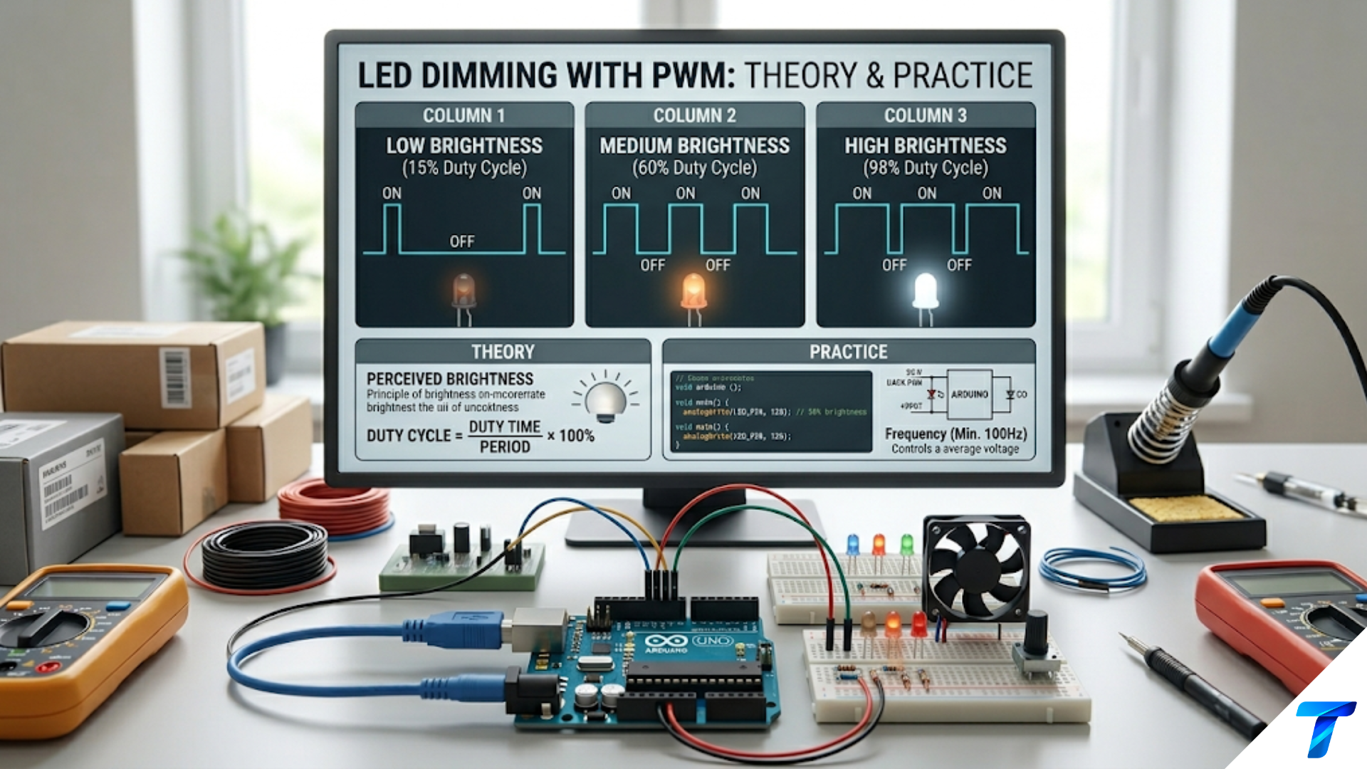
PWM (Pulse Width Modulation) is a technique for controlling the average power delivered to a load by rapidly switching a signal between fully ON and fully OFF, varying how long the signal stays ON during each cycle. The fraction of time the signal is ON — called the duty cycle — determines the effective output: a 50% duty cycle delivers half the maximum power, 75% delivers three-quarters. PWM is used everywhere in electronics for motor speed control, LED dimming, power conversion, and generating analog signals from digital outputs — all without the energy waste of resistive control methods.
Introduction: The Problem With Partial Power
Imagine you want to control the brightness of a light bulb. The simplest approach is to put a variable resistor (rheostat) in series with the bulb and turn it up to reduce the current. It works — but every watt you take away from the bulb gets wasted as heat in the resistor instead. At half brightness, you are dissipating half the supply power in a resistor doing nothing useful. The efficiency ceiling is low, the resistor gets hot, and the system wastes energy.
The same problem appears when controlling motor speed with a resistor, regulating voltage with a linear regulator, or adjusting any other electrical quantity by absorbing the unwanted portion as heat. Linear control is inherently inefficient — the power you do not deliver to the load is dissipated as heat somewhere in the control element.
PWM solves this problem by thinking about power delivery differently. Instead of partially conducting — maintaining a state somewhere between fully on and fully off — PWM switches rapidly between two states: completely on (near-zero voltage drop across the switch, near-zero loss) and completely off (zero current, zero loss). The average power delivered to the load is controlled not by how hard the switch conducts but by how long it is on during each cycle.
An ideal switch dissipates no power in either state: when on, the voltage across it is essentially zero; when off, the current through it is zero. In both cases, power (voltage × current) is zero. Real losses only occur during the brief transitions between states. By minimizing transition time — using fast MOSFETs that switch in nanoseconds — switching power losses are kept very small. The result is a control method that can achieve 90–99% efficiency where a linear approach might achieve 40–60%.
This efficiency advantage has made PWM the dominant technique in virtually all modern power control: switching power supplies, motor controllers, LED drivers, solar charge controllers, class D amplifiers, and microcontroller analog outputs all rely on it. Understanding PWM — not just what it does but how it works, what its parameters mean, and how they interact with real loads — is essential knowledge for modern electronics design.
The Core Concept: Duty Cycle and Average Value
Defining the PWM Signal
A PWM signal is a periodic waveform that alternates between a HIGH level (V_high) and a LOW level (typically 0V for digital PWM). Every cycle has the same total duration — the period T. What changes is how the period is divided between the ON time and the OFF time.
Duty cycle is the fraction of each period that the signal spends HIGH:
Duty cycle (D) = t_on / TWhere t_on is the ON time per cycle and T is the total period. Duty cycle is usually expressed as a percentage:
- D = 0%: signal always LOW (never ON)
- D = 25%: signal is HIGH for one quarter of each cycle
- D = 50%: signal is HIGH for exactly half of each cycle
- D = 75%: signal is HIGH for three quarters of each cycle
- D = 100%: signal always HIGH (continuously ON)
The PWM frequency f = 1/T determines how many complete on-off cycles happen per second.
Average Voltage and Average Power
The average value of a PWM signal is directly proportional to the duty cycle:
V_average = D × V_highExamples (V_high = 5V):
- D = 25%: V_average = 1.25V
- D = 50%: V_average = 2.5V
- D = 75%: V_average = 3.75V
This linear relationship between duty cycle and average voltage is the fundamental property that makes PWM so useful for proportional control. Varying the duty cycle from 0% to 100% varies the average output smoothly and linearly from 0V to V_high.
Average power to a resistive load R:
P_average = V²_average / R = (D × V_high)² / R = D² × P_maxNote that power scales with D² for resistive loads — doubling the duty cycle from 25% to 50% quadruples the power, not doubles it. This matters for heater elements and incandescent bulbs but less so for inductive loads like motors, where the inductance smooths the current and power is more closely proportional to D.
RMS voltage (relevant for resistive loads and heating):
V_RMS = V_high × √DFor a heater element: P = V²_RMS / R = D × V²_high / R — linearly proportional to D. At 50% duty cycle, half the maximum heating power is delivered. This is why PWM works so intuitively for heating applications.
A Visual Picture
Imagine a 10ms period (100Hz PWM) with V_high = 12V:
D = 25%: Signal is HIGH for 2.5ms, LOW for 7.5ms. Average = 3V.
12V ─┐   ┌────────────────────────────
     │   │
  0V ┘   └────────────────────────────
|2.5ms| 7.5ms |D = 75%: Signal is HIGH for 7.5ms, LOW for 2.5ms. Average = 9V.
12V ──┐───────────────────────┐
      │                       │
  0V ─┘                       └────────
      |        7.5ms          |  2.5ms |
Same frequency, same amplitude, completely different average value — controlled entirely by the relative timing of the ON and OFF intervals.
Why PWM Is Efficient: The Switching Argument
To understand why PWM is so much more efficient than linear control, compare the two approaches for reducing an LED from full brightness to half brightness using a 5V supply:
Linear approach (series resistor): LED forward voltage = 2V, desired current = 10mA (full brightness). At full brightness: R = (5V − 2V) / 10mA = 300Ω, P_resistor = 10mA × 3V = 30mW wasted.
For half brightness (5mA): R = (5V − 2V) / 5mA = 600Ω, P_resistor = 5mA × 3V = 15mW wasted. P_LED = 5mA × 2V = 10mW delivered. Efficiency = 10 / (10 + 15) = 40%.
PWM approach (50% duty cycle): D = 50%: LED switches at full current (20mA) for half the time, off for half the time. Average current = 10mA — same perceived brightness. P_switch_losses ≈ 0 (ideal switch). P_LED = 10mA_average × 2V = 20mW delivered (same light output). Efficiency ≈ 100% (ignoring tiny switching losses).
PWM delivers the same average brightness at nearly twice the efficiency. For a motor running at half speed, the difference is even more dramatic — and at high power levels (kilowatts), the energy savings are enormous.
The physical reason: A switch in the fully-on state has near-zero voltage across it, so V × I ≈ 0. A switch in the fully-off state has near-zero current through it, so V × I ≈ 0. Power is only dissipated during transitions, which for a fast MOSFET take nanoseconds out of a microsecond period — a tiny fraction of total time.
PWM Frequency: Why It Matters
The choice of PWM frequency is one of the most important design decisions. Different applications have very different requirements.
Frequency and Current Ripple (Inductive Loads)
When PWM drives an inductive load (a motor, solenoid, or inductor), the inductance resists instantaneous current changes. During the ON time, current rises; during the OFF time, it falls (through a freewheeling diode or the complementary switch). The magnitude of this current ripple:
ΔI_ripple = (V × D × (1−D)) / (L × f_PWM)Where V is the supply voltage, L is the load inductance, and f_PWM is the switching frequency.
This formula shows:
- Current ripple decreases with higher frequency — higher f means less time for current to rise or fall per cycle
- Current ripple is maximum at D = 50%
- Higher inductance reduces ripple for a given frequency
Worked example: 12V supply, D = 0.5, L = 2mH (typical small DC motor), f_PWM = 1kHz:
ΔI_ripple = (12 × 0.5 × 0.5) / (0.002 × 1,000) = 3 / 2 = 1.5A — very largeSame motor at f_PWM = 20kHz:
ΔI_ripple = 3 / 40 = 75mA — excellentHigher frequency gives smoother current and therefore smoother motor operation. This is why 20kHz is the widely-adopted standard for motor PWM — it is above the human hearing range (silent) AND provides excellent current smoothing.
Audible Noise
Below about 20kHz, PWM switching causes audible noise. Motor windings vibrate at the switching frequency through magnetostriction (magnetic material physically changing shape with the magnetic field). Capacitors and inductors also vibrate. At 1kHz, this produces a clearly audible whine; at 5kHz, a higher-pitched tone; above 20kHz, it is inaudible to humans.
For any application where noise matters — indoor robots, consumer devices, medical equipment — use f_PWM ≥ 20kHz. For applications where noise is irrelevant (industrial equipment in noisy environments, simple battery chargers), lower frequencies may be acceptable.
Switching Losses
Every time the switch transitions from off to on or on to off, a small amount of energy is lost. These switching losses occur because the switch passes through a region where both voltage and current are simultaneously non-zero during the transition:
P_switching ≈ 0.5 × V × I × t_transition × f_PWM × 2Switching losses scale linearly with frequency. At 1kHz, switching losses are minimal. At 1MHz, they may dominate. This creates a fundamental tradeoff: higher frequency reduces current ripple and audible noise but increases switching losses.
For a given application, the optimal frequency balances these competing factors. Typical ranges:
| Application | Typical f_PWM | Reasoning |
|---|---|---|
| LED dimming | 200Hz–20kHz | Above flicker threshold; no ripple concern |
| DC motor control | 15kHz–25kHz | Silent, good ripple for typical inductances |
| Stepper driver chopper | 20kHz–50kHz | Low ripple needed for smooth microstepping |
| Switching power supply | 50kHz–500kHz | Compact magnetics; efficiency tradeoff |
| Class D audio | 200kHz–1MHz | Must be >> 20kHz audio bandwidth |
How PWM Interacts With Different Loads
Resistive Loads (Heaters, Incandescent Bulbs)
For a purely resistive load, current is directly proportional to voltage at every instant. During the ON time, full current flows; during the OFF time, zero current flows. No energy storage occurs.
The thermal mass of the load determines whether it responds to individual PWM cycles or only to the average:
- High thermal mass (oven element, space heater): Temperature responds only to average power. Any PWM frequency above a few Hz works — the element never cools noticeably between pulses. PWM frequency is irrelevant above ~10Hz.
- Low thermal mass (incandescent bulb filament): Filament temperature varies with each cycle at low frequencies, causing visible flicker. Above ~100Hz, thermal inertia prevents significant temperature variation between pulses. Use f_PWM ≥ 200Hz to prevent visible flicker; higher for video camera compatibility.
Inductive Loads (Motors, Solenoids, Relays)
Inductors oppose instantaneous current changes — V = L × dI/dt. When PWM voltage is applied, current rises exponentially during the ON time and decays during the OFF time. If the PWM frequency is high enough relative to the electrical time constant τ = L/R, the current barely changes during each cycle — it settles at a nearly constant value equal to V_average / R.
This current-smoothing property of inductance is what makes PWM so effective for motor control. The motor “sees” the average voltage as a smooth DC source, not the switching waveform. Its speed is proportional to the average voltage; its current (and therefore torque) is proportional to the average current, with only small ripple around the mean.
Essential: the freewheeling diode. When the PWM switch turns OFF, the inductor tries to maintain current flow. Without a path for that current, the voltage across the inductor spikes to many times the supply voltage — potentially destroying the switch. A freewheeling diode (placed across the motor or inductor, anode toward the lower terminal) provides a path for the inductor current to continue flowing when the switch opens, clamping the voltage spike.
For H-bridge motor control: The body diodes of the MOSFETs serve as freewheeling diodes, or the complementary switch is turned on synchronously (synchronous rectification). No additional diodes are needed.
Capacitive Loads
For a capacitor load, each PWM ON pulse charges the capacitor toward V_high; each OFF interval allows partial discharge. The resulting output voltage is a sawtooth ripple around the average value. The ripple amplitude:
ΔV_ripple ≈ I_load / (C × f_PWM)Higher frequency reduces ripple on capacitive outputs. This principle underlies PWM-based DAC (digital-to-analog conversion) using an RC filter.
PWM as a DAC: Generating Analog Voltages
A PWM signal passed through a low-pass RC filter produces a smooth analog voltage proportional to the duty cycle. This “PWM DAC” technique allows a microcontroller with no real DAC to generate analog output voltages.
The RC Low-Pass Filter
A simple RC filter (resistor in series, capacitor to ground) attenuates high-frequency components while passing the DC average:
f_cutoff = 1 / (2π × R × C)For good filtering (ripple below 1% of full-scale), the cutoff frequency should be much lower than the PWM frequency:
f_cutoff << f_PWM (typically f_cutoff ≤ f_PWM / 50)Design example: f_PWM = 1kHz, desired ripple < 10mV (with 5V full scale = 0.2%):
Required attenuation at 1kHz: 10mV / 5V = 0.002 = −54dB
For a single-pole RC filter: attenuation ≈ f_cutoff / f_PWM at frequencies well above f_cutoff.
f_cutoff ≈ 0.002 × 1,000 = 2Hz
R × C = 1 / (2π × 2) = 79.6msWith R = 10kΩ: C = 79.6ms / 10,000 = 7.96µF → use 10µF electrolytic + 100nF ceramic in parallel.
Response time tradeoff: A very low cutoff frequency (good ripple rejection) means the output responds slowly to duty cycle changes — the RC time constant (79.6ms) determines how quickly the output settles to a new value. For slowly-varying signals (setpoint control, bias voltages), this is fine. For fast control loops, a higher PWM frequency allows a higher cutoff frequency with the same ripple ratio, giving faster response.
Two-stage filter: A second RC stage rolls off at −40dB/decade instead of −20dB, achieving much better ripple rejection for the same bandwidth. Two stages of R = 1kΩ, C = 10µF each (f_cutoff = 15.9Hz each) combined give roughly 100× better ripple rejection than a single stage.
Practical limit: PWM DAC works well for low-frequency, moderate-precision applications. For audio-frequency signals or high-accuracy analog outputs, a dedicated DAC IC (such as the MCP4725 over I²C) is far more practical.
How Microcontrollers Generate PWM
Modern microcontrollers generate PWM in hardware using dedicated timer peripherals — no CPU time required for the actual switching.
The Timer/Counter Mechanism
A hardware counter increments from 0 to a TOP value at the timer clock frequency, then resets to 0 and repeats. A compare register (OCR — Output Compare Register) holds the desired pulse width count. The output pin is controlled automatically:
- When counter < OCR: output HIGH
- When counter ≥ OCR: output LOW (for one common polarity; inverted in some modes)
The duty cycle:
D = OCR / TOPThe PWM frequency:
f_PWM = f_clock / (TOP × prescaler)Changing OCR changes the duty cycle. Changing TOP (or the prescaler) changes the frequency.
PWM Resolution
Resolution is the number of distinct duty cycle steps:
Resolution (bits) = log₂(TOP + 1)- TOP = 255: 8-bit resolution (256 steps, 0.39% per step)
- TOP = 1023: 10-bit resolution (1024 steps, 0.098% per step)
- TOP = 4095: 12-bit resolution (4096 steps, 0.024% per step)
There is a direct tradeoff between resolution and frequency. For a 16MHz clock and prescaler = 1:
f_PWM = 16MHz / (TOP + 1)- 8-bit (TOP=255): f_PWM = 62.5kHz
- 10-bit (TOP=1023): f_PWM = 15.6kHz
- 16-bit (TOP=65535): f_PWM = 244Hz
For applications needing both high resolution AND high frequency, a faster clock is needed. 32-bit ARM microcontrollers running at 72–200MHz can achieve high resolution and high frequency simultaneously.
Arduino PWM: What analogWrite() Does
The Arduino analogWrite(pin, value) function generates PWM with:
- 8-bit resolution: value 0–255 maps to D = 0%–100%
- Default frequency varies by timer and pin:
- Pins 5, 6 (Timer 0): ~980Hz
- Pins 9, 10 (Timer 1): ~490Hz
- Pins 3, 11 (Timer 2): ~490Hz
These defaults are often problematic:
- 490Hz is audible — motors whine, coils buzz
- For LED dimming with cameras, 490Hz can cause flicker in video
- For switching supplies, 490Hz needs very large filter components
Changing Arduino PWM frequency requires manipulating timer prescaler registers directly — not available through analogWrite():
// Set Timer 1 (pins 9, 10) to ~31kHz (prescaler = 1):
TCCR1B = (TCCR1B & 0b11111000) | 0x01;

// Set Timer 2 (pins 3, 11) to ~31kHz:
TCCR2B = (TCCR2B & 0b11111000) | 0x01;For 20kHz precisely on Timer 1 using phase-correct PWM:
// Phase-correct PWM, f = 16MHz / (2 × prescaler × TOP)
// For 20kHz: TOP = 16MHz / (2 × 1 × 20000) = 400
TCCR1A = _BV(COM1A1) | _BV(WGM11);
TCCR1B = _BV(WGM13) | _BV(CS10);  // prescaler = 1
ICR1 = 400;                          // TOP = 400
OCR1A = 200; // 50% duty cycleSetting OCR1A from 0 to 400 gives 0%–100% duty cycle at 20kHz.
Fast PWM vs. Phase-Correct PWM
Fast PWM: Counter counts up from 0 to TOP, then resets. Simple and produces the highest frequency for a given clock and TOP. The output edge is asymmetric — the rising edge always occurs at counter = 0, the falling edge at counter = OCR.
Phase-correct PWM: Counter counts up from 0 to TOP, then back down from TOP to 0. Output goes HIGH on the way up when counter = OCR, LOW on the way down when counter = OCR again. The PWM waveform is symmetric around the center of the period. Frequency is half that of fast PWM for the same TOP value.
Phase-correct PWM is preferred for motor control because the symmetric waveform reduces harmonic content, leading to smoother current and less electromagnetic interference. Fast PWM is preferred where maximum frequency is needed.
PWM Frequency Selection: A Practical Guide
LED Dimming
Human flicker threshold: ~100Hz (some people detect up to 200Hz in peripheral vision). PWM above 200Hz is imperceptible to most people.
Camera compatibility: Video cameras operating at 24, 25, 30, or 60 fps can show flicker or banding when f_PWM is not harmonically related to the frame rate. Use f_PWM ≥ 1kHz for general lighting. For studio or cinema use, 10kHz+ is common.
Color quality: PWM dimming maintains LED color temperature — the forward current during the ON time is always the same, preserving the emission spectrum. Resistive (analog) dimming reduces current and shifts color temperature. This makes PWM dimming preferable for color-critical applications like photography lighting, display backlights, and horticulture LEDs.
Recommendation: 1kHz minimum for general use; 10kHz+ for video; 20kHz for absolutely silent operation.
DC Motor Speed Control
Below 1kHz: Audible motor noise (whining or buzzing). High current ripple. Acceptable only for non-critical, noisy environments.
1kHz–5kHz: Some audible noise. Moderate ripple. Usable if noise is not a concern.
5kHz–20kHz: Reduced noise. Good ripple performance for most motor inductances. Upper limit of audibility.
20kHz–100kHz: Silent. Excellent current smoothing. Increased switching losses require more careful MOSFET and gate drive design.
Recommendation: 20kHz for most motor applications — the universal sweet spot between silence, ripple performance, and switching efficiency.
Power Supplies
50kHz–200kHz: Standard range balancing efficiency and component size. Most off-the-shelf PWM controller ICs target this range.
200kHz–1MHz: Very compact magnetics. Higher switching losses require advanced MOSFET technology. Used in laptop power bricks and high-density converters.
> 1MHz (GaN converters): Cutting-edge gallium nitride transistors enable megahertz switching with acceptable losses. Used in the smallest, highest-power-density adapters and chargers.
EMI and Harmonics
PWM generates electromagnetic interference (EMI) because every switching edge creates voltage and current transients that radiate and conduct across a wide frequency range. Understanding this is important for any design that must pass regulatory testing (FCC in the USA, CE in Europe).
Harmonic Content
A PWM signal contains energy at the fundamental switching frequency and all harmonics — 2×, 3×, 4×f_PWM and beyond. At 50% duty cycle, even harmonics cancel (only odd harmonics remain). The harmonic amplitudes fall with frequency but extend well into the MHz range, potentially interfering with AM radio, WiFi, Bluetooth, and other communications.
Managing PWM-Generated EMI
Gate resistors: Adding resistance in the MOSFET gate drive slows the switching transitions. Slower transitions reduce high-frequency harmonic amplitudes at the cost of slightly higher switching losses. A 10Ω to 100Ω gate resistor is a practical compromise.
Snubber circuits: Small RC networks (often 10Ω + 10nF) across the switch absorb voltage spikes from wiring inductance and reduce ringing at switching edges.
Spread spectrum PWM: Some PWM controllers deliberately vary the switching frequency slightly (±5% dither) from cycle to cycle, spreading the EMI energy across a band of frequencies rather than concentrating it at f_PWM and its harmonics. This can reduce peak emissions by 10–20dB.
Physical layout: Short wiring in the switching current loop minimizes loop inductance and therefore minimizes the voltage spikes and EMI from switching transients.
Complete Design Examples
Design Example 1: Arduino LED Dimmer (Flicker-Free)
Goal: Dim an LED smoothly and silently using Arduino PWM, compatible with video cameras.
Problem with default: analogWrite() on pin 9 defaults to 490Hz — borderline for flicker, audible in coils near the LED driver circuit.
Solution: Change Timer 1 to ~31kHz:
void setup() {
  // Set Timer 1 prescaler to 1 → ~31.4kHz PWM on pins 9 and 10
  TCCR1B = (TCCR1B & 0b11111000) | 0x01;
  pinMode(9, OUTPUT);
}

void loop() {
  // Fade up with gamma correction for perceptually linear brightness
  for (int i = 0; i <= 255; i++) {
    // Gamma 2.2 correction: maps linear 0-255 to perceived linear brightness
    float gamma = 2.2;
    int corrected = (int)(255.0 * pow(i / 255.0, gamma));
    analogWrite(9, corrected);
    delay(8);  // 2-second fade
  }
  // Fade down
  for (int i = 255; i >= 0; i--) {
    float gamma = 2.2;
    int corrected = (int)(255.0 * pow(i / 255.0, gamma));
    analogWrite(9, corrected);
    delay(8);
  }
}Why gamma correction: Human brightness perception is logarithmic. A linear ramp from 0 to 255 in PWM value produces a visible jump from dark to medium brightness in the first quarter of travel, then barely perceptible change in the upper three quarters. Gamma correction maps the control value to a perceptually uniform brightness scale.
LED circuit: Arduino pin 9 → 220Ω → LED anode → LED cathode → GND. The resistor limits current to (5V − 2V) / 220Ω ≈ 14mA.
Design Example 2: 12V DC Motor Speed Controller
Goal: Control a 12V, 2A brushed DC motor speed from 0–100% using a MOSFET low-side switch and Arduino.
MOSFET selection: IRLZ44N (logic-level, 55V, 47A, R_DS(on) = 22mΩ at 5V gate drive). Overkill for 2A but provides zero thermal concerns.
Freewheeling diode: 1N5819 Schottky diode across motor terminals (anode to ground/drain side, cathode to positive supply). Schottky chosen for fast recovery and low forward voltage.
Gate resistor: 100Ω limits peak gate current to (5V − 0V) / 100Ω = 50mA — within Arduino GPIO limits during the brief switching transition at 20kHz.
PWM generation at 20kHz:
void setup() {
  // Timer 1 phase-correct PWM at 20kHz on pin 9
  TCCR1A = _BV(COM1A1) | _BV(WGM11);
  TCCR1B = _BV(WGM13) | _BV(CS10);  // no prescaler
  ICR1 = 400;   // TOP for 20kHz
  OCR1A = 0;    // Start at 0% speed
  pinMode(9, OUTPUT);
}

void setMotorSpeed(uint8_t percent) {
  OCR1A = (uint32_t)ICR1 * percent / 100;
}

void loop() {
  // Ramp up
  for (int s = 0; s <= 100; s += 5) {
    setMotorSpeed(s);
    delay(50);
  }
  delay(1000);
  // Ramp down
  for (int s = 100; s >= 0; s -= 5) {
    setMotorSpeed(s);
    delay(50);
  }
  delay(1000);
}Conduction losses at 2A:
P_cond = I² × R_DS(on) × D = 4 × 0.022 × 0.5 = 44mW (at 50% duty cycle)No heatsink required. The MOSFET runs cool even at full load.
Switching losses at 20kHz:
P_sw ≈ 0.5 × 12V × 2A × t_sw × f × 2 transitions
t_sw ≈ R_gate × Q_gd / V_gate = 100Ω × 22nC / 5V ≈ 440ns
P_sw ≈ 0.5 × 12 × 2 × 440ns × 20,000 × 2 = 211mWTotal dissipation ≈ 255mW — still no heatsink needed for IRLZ44N (TO-220, θ_JA = 62°C/W: ΔT = 15.8°C above ambient).
Design Example 3: PWM DAC — Analog Output From Digital Pin
Goal: Generate a smooth 0–3.3V analog output from an ESP32 GPIO pin for a sensor bias voltage or analog set point.
ESP32 LEDC (LED Control) peripheral: Provides high-resolution PWM suitable for DAC applications.
const int PWM_PIN = 25;
const int PWM_CHANNEL = 0;
const int PWM_FREQ = 50000;   // 50kHz
const int PWM_RESOLUTION = 12; // 12-bit: 0–4095

void setup() {
  ledcSetup(PWM_CHANNEL, PWM_FREQ, PWM_RESOLUTION);
  ledcAttachPin(PWM_PIN, PWM_CHANNEL);
}

// Set output voltage 0.0 to 3.3V
void setVoltage(float volts) {
  int duty = (int)(volts / 3.3 * 4095);
  duty = constrain(duty, 0, 4095);
  ledcWrite(PWM_CHANNEL, duty);
}RC filter design for 50kHz PWM:
Desired ripple < 1mV (for a 3.3V full-scale output, this is < 0.03%):
Required attenuation at 50kHz: 1mV / 3300mV = 0.0003
For a two-stage RC filter (−40dB/decade): each stage needs f_cutoff = √(0.0003) × 50kHz…
Practically: use two stages with f_cutoff = 100Hz each (R = 10kΩ, C = 160nF → use 150nF):
- Stage 1: R1 = 10kΩ, C1 = 150nF → f_c = 106Hz
- Stage 2: R2 = 10kΩ, C2 = 150nF → f_c = 106Hz
Combined attenuation at 50kHz ≈ (106/50,000)² = 4.5×10⁻⁶ → ripple = 3.3V × 4.5×10⁻⁶ = 15µV — extremely clean.
Buffer the output: Two-stage RC filter has 20kΩ output impedance. Buffer with an op-amp voltage follower (MCP6001) before connecting to any load that draws current.
Settling time: With f_cutoff = 106Hz, the RC time constant = 1/(2π × 106) ≈ 1.5ms per stage. Full settling to a new value (within 1%) ≈ 5 × time_constants ≈ 15ms for two stages. Adequate for slow setpoint control; too slow for fast signal generation.
Design Example 4: Heating Element Controller (Oven Temperature Control)
Goal: Control a 240V AC, 1500W oven heating element using PWM to maintain temperature. Use solid-state relay (SSR) for mains isolation.
Why PWM for AC heating: The SSR turns AC power on and off. For a 1500W element, even short bursts deliver significant energy. Use slow PWM (1–10 second period) — within the heater’s thermal time constant — to avoid cycling the SSR too rapidly (SSR rated for typical on-off cycles, not 20kHz switching).
Period selection: Heater thermal time constant ≈ 30 seconds (large thermal mass). Using T_PWM = 10 seconds (f = 0.1Hz): at 70% duty cycle, heater is on for 7 seconds, off for 3 seconds. The temperature barely ripples — completely smooth effective heating.
Circuit:
Microcontroller GPIO → SSR input (3–32V DC control) → SSR output (240V AC) → Heater
Thermocouple → MAX31855 → SPI → Microcontroller (temperature feedback)PID control with PWM output:
// Simple P-only controller for illustration
float target_temp = 180.0;   // degrees C

void loop() {
  float current_temp = readThermocouple();  // from MAX31855
  float error = target_temp - current_temp;

  // Proportional control: Kp = 2.0% per degree error
  float duty = 50.0 + (error * 2.0);  // 50% base + correction
  duty = constrain(duty, 0, 100);

  // Apply duty cycle over 10-second window
  if (duty > 0) {
    digitalWrite(SSR_PIN, HIGH);
    delay((int)(duty * 100));  // ON time in ms (0-10000ms)
    digitalWrite(SSR_PIN, LOW);
    delay((int)((100 - duty) * 100));  // OFF time
  } else {
    delay(10000);
  }
}Safety note: Always include independent over-temperature protection (a separate thermostat or thermal fuse) when controlling mains-powered heating elements. Never rely solely on software for safety-critical temperature limits.
Summary
Pulse Width Modulation controls power delivery by varying how long a signal stays HIGH during each fixed period — the duty cycle. Average output voltage equals D × V_high; for inductive loads, this provides smooth, efficient control without the energy waste of resistive methods.
PWM frequency is the central design parameter, governing three competing factors: current ripple (decreases with higher frequency), audible noise (above 20kHz is silent), and switching losses (increase linearly with frequency). For motor control, 20kHz balances all three. For LED dimming, 1kHz minimum prevents flicker. For switching supplies, 50kHz–500kHz balances efficiency and component size.
Microcontrollers generate PWM in hardware using timer/counter peripherals — a counter compared against an output compare register. The duty cycle (OCR/TOP) and frequency (f_clock / TOP / prescaler) are independently programmable. Arduino’s default 490Hz PWM is too low for most applications; changing the timer prescaler to achieve 15–31kHz is often necessary.
Through an RC low-pass filter, PWM generates smooth analog voltages from digital hardware — a simple DAC. The filter cutoff must be much lower than the PWM frequency for good ripple rejection, trading off against output response speed.
Understanding PWM — its mathematics, its interaction with different load types, its frequency tradeoffs, and its hardware implementation — unlocks the door to motor control, power conversion, signal generation, and the majority of modern embedded power electronics.