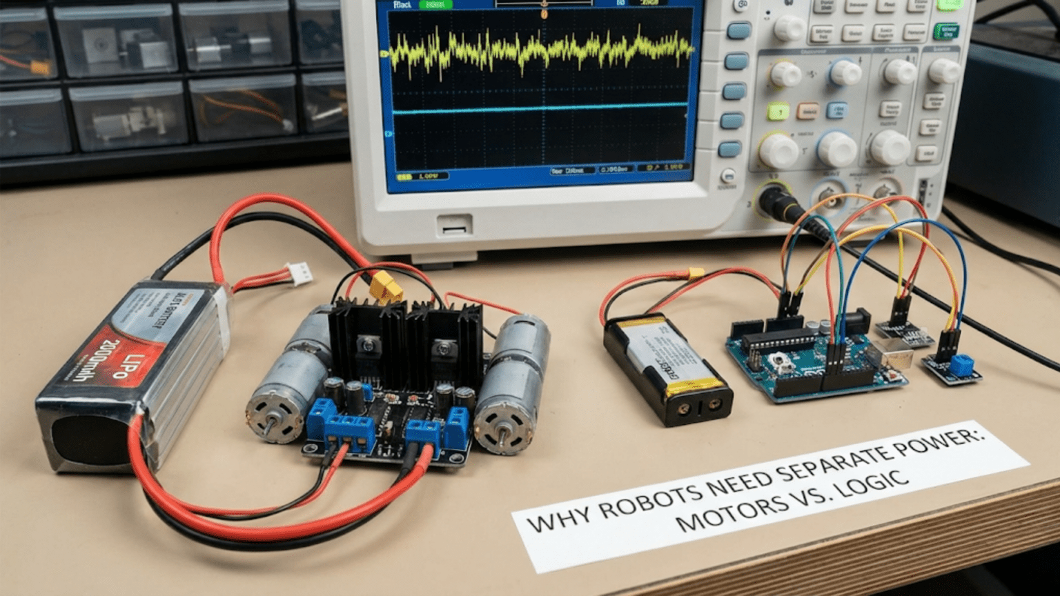
Robots need separate power supplies for motors and logic electronics because motors are electrically noisy, high-current loads that create two distinct problems on a shared power rail: voltage sag—the instantaneous voltage drop when motor current surges causes microcontrollers to reset and sensors to misread—and conducted electrical noise—the high-frequency interference generated by motor brushes, PWM switching, and back-EMF spikes that corrupts digital communication, sensor readings, and program execution when it reaches logic circuits through a shared supply. Separating motor and logic power physically isolates these problems so motors can create as much electrical interference as they need to without affecting the sensitive electronics that control them.
You’ve built what seems like a perfectly functional robot. The motors work when tested individually. The sensors give accurate readings on the bench. The microcontroller runs your program without issue. But when everything is connected and the robot drives for the first time, strange things happen: the Arduino occasionally resets mid-run, sensor readings jump to impossible values just as the motors accelerate, I2C communication fails at seemingly random moments, servo positions drift when the drive motors engage, and the robot occasionally just freezes and needs a power cycle to recover.
Every one of these symptoms has the same root cause: motors and logic electronics sharing a power supply without proper isolation.
This is one of the most common and most frustrating problems in beginner and intermediate robotics. It’s frustrating because the problems are intermittent—they don’t happen on the bench with motors disconnected, they don’t happen with light motor loads, and they don’t always happen in the same place in the code. They seem like software bugs or bad sensors, but they are almost always a power problem.
Understanding why motors and logic circuits are fundamentally incompatible on a shared power supply—and knowing the techniques to properly isolate them—is one of the most important skills for building reliable robots. This article gives you that understanding completely.
The Two Root Causes: Voltage Sag and Electrical Noise
The problems that motors cause for logic circuits fall into two distinct categories that require different solutions. Understanding each separately makes the solutions logical rather than arbitrary.
Root Cause 1: Voltage Sag
Every battery and power supply has internal resistance. When current flows through that internal resistance, it causes a voltage drop—the terminal voltage of the supply drops below its open-circuit voltage. This is called voltage sag, and it’s directly proportional to current:
Voltage sag = Current drawn × Internal resistance

For a 3S LiPo battery with 0.05Ω internal resistance:
At 1A load:   Sag = 1A × 0.05Ω = 0.05V  (barely noticeable)
At 5A load:   Sag = 5A × 0.05Ω = 0.25V  (small but measurable)
At 20A load:  Sag = 20A × 0.05Ω = 1.0V  (significant)
At 40A load: Sag = 40A × 0.05Ω = 2.0V (severe)For a nominal 11.1V battery, a 2V sag leaves only 9.1V at the battery terminals during the peak current event. But the voltage drop doesn’t just affect the battery terminals—it propagates through every wire in the power distribution system. If the logic electronics share the same power path, the same voltage drop hits their supply rail.
For a 5V-regulated logic supply, the situation is slightly different but equally problematic: the regulator input voltage drops during the motor surge. If the input drops below the regulator’s minimum input voltage (the output voltage plus the dropout voltage), the regulator can no longer maintain its output and the 5V rail sags. Even a brief dip below 4.5V is enough to trigger the brownout reset on an Arduino Uno, which resets the microcontroller completely.
The timing of voltage sag makes it particularly insidious. The largest sag events occur at motor startup—the instant when the motor switches from stationary (infinite impedance, no back-EMF) to moving. During this brief window, motor current can approach stall current, which is typically 5–15 times the running current. A motor that draws 0.5A while running may draw 3–6A for the first 50–100ms of startup. That surge, multiplied across two or four motors starting simultaneously, creates a severe voltage dip right when the microcontroller is trying to execute its startup sequence.
Root Cause 2: Conducted Electrical Noise
Beyond voltage sag, motors generate high-frequency electrical interference that travels through the power supply wiring and corrupts digital circuits. This conducted noise has several distinct sources:
Brush commutation noise (DC brushed motors): As the rotating commutator segments make and break contact with the brushes, they create rapid current switching events—essentially thousands of tiny sparks per second. Each switching event generates a broad-spectrum electromagnetic pulse. At high motor speeds, these pulses occur at frequencies from a few hundred Hz to tens of kHz, and their harmonics extend into the MHz range.
PWM switching transients (motor drivers): When a motor driver switches the motor voltage on and off rapidly (PWM at 1–20 kHz), the fast switching of large currents creates voltage spikes and high-frequency harmonics. The rise and fall times of MOSFET switching (typically 10–100 ns) generate noise with spectral energy extending to 10–100 MHz.
Back-EMF spikes (inductive kickback): Motors are inductive loads. When motor current is switched off, the inductance tries to maintain current flow, generating a large voltage spike in the reverse direction. In a brushed motor driver without adequate flyback diode protection, these spikes can reach 50–100V—far above the supply voltage—before the flyback diodes clamp them. Even with protection diodes, residual spikes of several volts appear on the power supply rail.
Brush contact resistance variation: As the brush contact resistance varies with commutator rotation, it modulates the motor current and creates current ripple that appears as voltage ripple on the power supply.
All of these noise sources create high-frequency voltage fluctuations on the power supply rail. When logic circuits—microcontrollers, sensors, communication ICs—share this rail, the noise couples directly into their supply voltage. What the logic circuits see is not the clean, stable voltage their specifications assume, but a noisy, fluctuating supply that causes:
- Bit errors in I2C, SPI, and UART communication (a noise spike during a data transfer flips a bit)
- ADC corruption (noise on the supply reference corrupts analog-to-digital conversions)
- False interrupts (noise spikes trigger interrupt pins, causing the microcontroller to jump to unexpected code)
- Logic glitches (combinatorial logic briefly produces wrong outputs when supply voltage fluctuates)
- Register corruption (in extreme cases, noise causes incorrect data to be written to microcontroller registers)
- Program counter corruption (severe noise can corrupt the program counter, causing the microcontroller to jump to arbitrary code locations—the robot appears to “go crazy”)
Understanding Ground: The Hidden Connection
Even when motors and logic circuits appear to have “separate” power supplies (separate batteries or separate regulators), they often share a common ground connection—and this ground connection is a primary noise coupling path.
Ground as a Current-Return Path
Ground is not just a reference voltage—it’s the return path for all currents in the circuit. When a motor draws 5A, that 5A flows out of the battery positive terminal, through the motor driver, through the motor, back through the motor driver, and returns to the battery negative terminal through the ground wire.
If the motor ground and the logic ground share the same physical wire (or PCB trace), that 5A flows through the shared ground return path. The shared ground wire has resistance and inductance. The 5A motor current flowing through this resistance creates a voltage difference along the ground path—what looks like “ground” at one end of the wire is at a different voltage than “ground” at the other end.
Ground resistance example:
22 AWG wire, 30cm length: resistance ≈ 0.016Ω

Motor drawing 5A through this shared ground wire:
Voltage difference = 5A × 0.016Ω = 0.08V

This means the microcontroller's "ground" reference is 80mV above
the battery's negative terminal during motor operation.

For a 5V supply, 80mV represents a 1.6% supply variation — enough
to corrupt a 10-bit ADC reading by 16 LSBs.

At 20A motor current, the same wire creates a 320mV ground offset —
6.4% supply variation, corrupting ADC by 65 LSBs — unusable.This phenomenon—where different parts of a circuit’s ground are at different voltages due to resistive voltage drops in the shared ground conductor—is called a ground loop or ground offset, and it is one of the subtlest and most damaging forms of power system noise in robotics.
High-Frequency Ground Noise
Beyond the resistive ground offset, the inductance of shared ground wires causes additional high-frequency noise. When motor current changes rapidly (PWM switching, motor startup, commutation), the rate of change of current through the ground inductance creates a voltage spike:
V_spike = L × dI/dt

For a ground wire with 100nH inductance (typical for a 20cm wire):
Motor current changing from 0 to 5A in 100ns (MOSFET switching time):
dI/dt = 5A / 100ns = 50,000,000 A/s = 50 MA/s

V_spike = 100nH × 50 MA/s = 100 × 10⁻⁹ H × 50 × 10⁶ A/s = 5V!

A 5V spike on the ground reference of a 5V logic circuit means the
entire supply appears to swing from 5V to 10V for that nanosecond.This high-frequency ground bounce is exactly what causes microcontroller resets, communication errors, and sensor malfunctions during motor operation—even when the power supply rail itself appears clean.
Solutions: How to Properly Separate Motor and Logic Power
Understanding the two root causes—voltage sag and electrical noise—points directly to the solutions. The goal is to prevent motor voltage sag and motor noise from reaching the logic supply, and to prevent motor ground currents from flowing through the logic ground.
Solution 1: Separate Voltage Regulators
The most fundamental solution is giving motors and logic circuits separate voltage regulators fed from the same battery, rather than sharing a single regulator.
WRONG: Shared regulator

Battery → Single 5V Regulator → Logic AND Motor Driver
                                        ↓
                              Motors share same 5V rail

Motor current surge → voltage sag → logic circuits see sag → resets


CORRECT: Separate regulators

Battery ─┬──────────────────────────── Motor driver (direct or via motor regulator)
         │
         └── 5V Logic Regulator ──── Logic circuits only
                                      (Arduino, sensors, MCU, etc.)

Motor current surge only affects motor rail.
Logic regulator independently maintains stable 5V.With separate regulators, even a massive motor current surge that drops the battery voltage from 12V to 9V still leaves the logic regulator with enough input headroom to maintain its 5V output (assuming a dropout of less than 4V at the peak surge—which is true for most buck converters down to their minimum input voltage).
The key is that the logic regulator acts as an isolating buffer: it draws only the current its logic loads require (typically 0.5–2A) from the battery, and the motor’s multi-ampere surge current doesn’t flow through the logic regulator’s output stage at all.
Solution 2: Star Ground Architecture
For the ground system, the solution is ensuring motor ground currents never flow through the logic ground path. The technique is called star grounding (or single-point grounding):
WRONG: Daisy-chain ground
Battery(-) → Motor Driver GND → Logic GND → MCU GND
              ↑
        Motor return current flows through logic ground wire

CORRECT: Star ground
                    ┌─── Motor Driver GND (heavy wire, 16–18 AWG)
Battery(-) ─────────┤
(star point)        └─── Logic Ground (thin wire acceptable, 22–24 AWG)
                    └─── Sensor Ground (thin wire, 24–26 AWG)

Each subsystem has its own ground path back to the star point.
Motor currents flow only through the motor ground wire.
Logic currents flow only through the logic ground wire.
No mixing of ground return currents.In practice, the “star point” is typically the negative terminal of the battery or the main power distribution board. All ground connections run back to this single point through separate wires, rather than daisy-chaining through intermediate components.
Solution 3: Decoupling Capacitors at Every IC
Even with separate regulators and star grounding, some residual noise reaches logic circuits through parasitic coupling (magnetic fields, capacitive coupling between PCB traces). The local defense is decoupling capacitors—small capacitors placed directly at the power supply pins of every integrated circuit.
A decoupling capacitor is a local charge reservoir. When a brief noise spike or current demand occurs at an IC, the capacitor supplies the charge instantly from its stored energy, before the disturbance can propagate back through the supply wiring to the regulator. The noise is “decoupled” from the supply rail.
Mandatory decoupling capacitor placement:

For every IC, place these capacitors as close to the VCC and GND pins as possible:
- 100nF (0.1µF) ceramic capacitor: handles high-frequency noise (1MHz–100MHz range)
- 10µF electrolytic or tantalum: handles lower-frequency ripple (10kHz–1MHz range)

"As close as possible" means within 2–3mm of the IC pin, not 20mm away.
A capacitor 20mm from the IC pin has inductance in the connecting traces
that reduces its effectiveness at high frequencies.

For the Arduino power supply pin specifically:
- Add 100µF electrolytic + 100nF ceramic between the 5V and GND pins
  at the board's power connector (as close to the VIN/5V input as possible)
- This local reservoir supplies current during brief sag events
before the supply rail has time to droop// No code needed for capacitor placement, but here's how to detect
// if you have insufficient decoupling: add brownout detection
// If you see frequent brownout resets (BORF in MCUSR), add bulk capacitance
// The 100µF capacitor at the Arduino power input is the first thing to add
// Verify fix: check MCUSR at startup and log any brownout events
void checkResetCause() {
uint8_t cause = MCUSR;
MCUSR = 0;
if (cause & (1 << BORF)) {
Serial.println("WARNING: Previous reset was brownout — check power supply!");
// Brownout detected: add bulk capacitor to power input
}
}Solution 4: Flyback Diodes on All Motor Terminals
Brushed DC motors and solenoids are inductive loads. When the driving transistor or MOSFET switches off, the motor’s inductance generates a reverse voltage spike (back-EMF) that can reach 50–100V and last for microseconds. This spike travels back through the power supply wiring if not clamped.
Flyback diodes (also called freewheeling diodes or snubber diodes) provide a low-impedance path for the back-EMF spike current, clamping the spike to one diode drop above the supply voltage:
Motor terminal connections with flyback protection:

Supply (+) ──────┬──────────────── Motor (+)
                 │                     │
               [D1]                  [Motor]
               1N4007                   │
                 │                 Motor (-)
Supply (-) ──────┴──────────────── Motor (-)

D1 is reverse-biased during normal operation (doesn't conduct).
When motor supply is switched off, back-EMF forward-biases D1,
spike current flows through D1 rather than through the supply.
Spike is clamped to Vsupply + Vf(diode) ≈ Vsupply + 0.7V.

For PWM motor control, the freewheeling diode carries current
during every off-cycle of the PWM, so use a fast diode:
- 1N4007 (1A, 1000V) — adequate for small motors
- 1N5819 Schottky (1A, 40V) — better: lower Vf, faster recovery
- MBR2045 Schottky (20A, 45V) — for large motors

Most integrated motor driver ICs (L298N, DRV8833, TB6612) include
internal flyback diodes — check the datasheet before adding external ones.
Solution 5: Bulk Capacitors on the Motor Supply
Just as decoupling capacitors protect individual ICs from brief noise, bulk electrolytic capacitors on the motor supply bus absorb the motor startup surge current from the local bus capacitance rather than dragging it entirely from the battery. This reduces how much the battery voltage sags during motor startup.
Motor supply bulk capacitor:

Battery ──────────────────────┬──── Motor Driver
                              │
                           [C1]     Electrolytic, 470–2200µF, 25V
                              │     Low-ESR type preferred
                             GND

During motor startup:
Without C1: All surge current must come from battery through wiring
           → large voltage sag across wire resistance

With C1: Initial surge current supplied by C1 locally
         → reduced current demand from battery during surge
         → smaller voltage sag
         → C1 recharges slowly between surges

Select C1 based on acceptable sag:
ΔV = Q/C = I×t/C
For 10A surge, 10ms duration, max 1V sag:
C = I×t/ΔV = 10A × 0.01s / 1V = 0.1F = 100,000µF (impractical)

More realistic: reduce sag for very brief surge (1ms):
C = 10A × 0.001s / 1V = 10,000µF (large but feasible with several caps in parallel)

Practical approach: 1000–4700µF provides meaningful sag reduction
for normal motor startup events. Not enough to eliminate all sag,
but combined with separate regulators, dramatically improves stability.Solution 6: Ferrite Beads on Power Lines
Ferrite beads are inductors specifically designed to attenuate high-frequency noise (above ~1MHz) while passing DC and low-frequency current with minimal resistance. Placing a ferrite bead in series with the power supply line to sensitive circuits provides high-frequency isolation:
Motor supply noise blocking with ferrite bead:

Battery(+) ──── Motor Driver (high noise)
     │
    [FB]  ← Ferrite bead (e.g., Murata BLM31PG, 600Ω at 100MHz)
     │
5V Regulator ──── Logic circuits (low noise)

The ferrite bead passes DC current to the regulator with negligible resistance,
but presents high impedance to high-frequency noise components.

For robotics: ferrite beads rated for the operating current (1–3A typical)
Impedance at 100MHz: select 100–600Ω for effective filtering
Common types: BLM31PG601SN1 (600Ω at 100MHz, 2A), BLM18AG601SN1 (smaller)Practical Implementation: Power Separation for Three Common Robot Types
Type 1: Simple Differential Drive Robot (Arduino + 2 DC Motors)
This is the most common beginner configuration and the one where power separation problems are first encountered.
Recommended power architecture:
3S LiPo (11.1V)
     │
     ├─── Direct to motor drivers (L298N, DRV8833, or similar)
     │    (motors draw from battery directly, no regulation)
     │
     └─── 5V Buck Converter → Arduino + sensors
                              (logic circuits isolated from motor supply)

Grounding:
- Motor driver GND → battery negative (heavy wire, AWG 20)
- Buck converter input GND → same battery negative terminal
- Buck converter output GND → Arduino GND (shared logic ground)
- NO direct connection between motor driver output GND and Arduino GND
  except at the battery negative terminal (star point)

Additional protection:
- 470µF electrolytic across battery terminals (near motor driver)
- 100nF ceramic at each motor driver power pin
- 100nF + 10µF at Arduino 5V inputWhat this achieves: Motor current surges draw entirely from the battery and motor supply capacitance without flowing through the 5V regulator’s output or the Arduino’s power rail. The motor driver’s ground return current flows through a separate heavy wire directly to the battery, not through any logic circuit’s ground path.
Type 2: Raspberry Pi Robot with Multiple Sensors
A Raspberry Pi robot is particularly sensitive to power quality because the Pi requires both stable voltage and adequate current, and it has its own sophisticated power management that reacts to supply problems.
Recommended power architecture:
3S LiPo (11.1V)
     │
     ├─── Direct to motor drivers (heavy wire, AWG 18–20)
     │    └── 1000µF bulk cap near each motor driver
     │
     ├─── Buck #1 (12V→5V, 3A): Raspberry Pi only
     │    └── 100µF low-ESR + 100nF at Pi power input
     │
     └─── Buck #2 (12V→5V, 1A): Arduino + sensors
          └── 100µF + 100nF at Arduino power input
          └── 3.3V LDO from this 5V for I2C sensors

Why two 5V bucks instead of one?
- Raspberry Pi power consumption fluctuates 500mA–1800mA depending on CPU load
- These large fluctuations on a shared 5V rail would cause voltage ripple
  that affects Arduino ADC readings and sensor stability
- Separate supply means Pi load variations don't disturb sensor readings

Ground architecture:
- All three GND paths (motors, Pi supply, Arduino supply) meet at battery(-)
- Heavy wire (AWG 16) for motor ground return
- Standard wire for each regulator input ground
- Regulators have separate output grounds that only meet at battery negativeCode-side protection for Raspberry Pi:
# Monitor supply voltage from Arduino via serial
# Arduino reads battery voltage and sends warnings to Pi

import serial
import sys

ser = serial.Serial('/dev/ttyACM0', 9600)

def monitor_power():
    while True:
        if ser.in_waiting:
            line = ser.readline().decode().strip()
            if 'BATT_LOW' in line:
                voltage = float(line.split(':')[1])
                print(f"WARNING: Battery low ({voltage:.2f}V) — initiating safe shutdown")
                safe_shutdown()

def safe_shutdown():
    """Graceful shutdown preserving filesystem integrity"""
    import subprocess
    subprocess.run(['sudo', 'shutdown', '-h', 'now'])
sys.exit(0)Type 3: Robot Arm with High-Current Servo Motors
Robot arms with multiple high-current servos present a special challenge: the servos are both motors (noisy, high-current) and logic devices (they contain control electronics that require clean power for their internal MCUs).
Recommended power architecture:
High-current LiPo (2S or 3S, 20C+)
     │
     ├─── Servo power bus (5–7.4V, depending on servo specs)
     │    ├── 2200µF bulk cap at start of servo bus
     │    └── 100µF at each servo power connector
     │
     └─── Isolated 5V for main controller (buck converter)
          └── Optionally: separate 3.3V for sensors from this 5V

Key insight: servos have their own internal control electronics.
The servo control signal (PWM) is logic-level — 3.3V or 5V.
The servo power (motor) can be 4.8V–7.4V depending on servo model.

NEVER power a servo's signal pin from the motor power bus.
Use the logic-level 5V (from the isolated supply) for signal lines.
Servo power and servo signal have separate return paths (separate GNDs
that meet only at the battery negative terminal).

Problem this prevents: high-current servo motor operation creating noise
that travels back through the signal wire to the controller's signal pin.
This manifests as servo jitter during coordinated multi-servo movements.
Diagnosing Whether You Have a Power Separation Problem
If you’re unsure whether your robot’s problems are power-related, use this diagnostic sequence:
Test 1: Disconnect motors completely. If all strange behaviors (resets, sensor errors, communication failures) disappear with motors disconnected and return when motors are connected, the problem is power-related.
Test 2: Connect motors but don’t move them. If problems occur only when motors run (not when merely connected), the issue is conducted noise or voltage sag during operation—consistent with motor interference.
Test 3: Reduce motor PWM duty cycle. Running motors at 30% PWM instead of 100% reduces current draw and switching noise. If problems reduce or disappear at lower PWM, current/noise is the cause.
Test 4: Measure supply voltage during motor operation. Use an oscilloscope or a fast multimeter with MIN/MAX capture across the 5V supply while the motors run. Dips below 4.5V indicate voltage sag causing brownout resets. High-frequency noise on the supply indicates conducted motor noise.
Test 5: Add a 470µF capacitor directly across the Arduino’s 5V and GND pins. If this improves stability, you have a voltage sag problem (the capacitor is smoothing brief dips). If it doesn’t help but moving the ground connection point does, you have a ground loop problem.
The Decoupling Capacitor Placement Guide
Correct capacitor placement is as important as selecting the right capacitor values. A capacitor placed far from the IC it’s protecting is significantly less effective due to the inductance of the PCB traces between the capacitor and the IC:
Effectiveness of decoupling capacitor vs. distance from IC:
At 10MHz, a 5cm trace has ~25nH inductance
Impedance of 25nH at 10MHz = 2π × 10MHz × 25nH ≈ 1.6Ω

This trace impedance partially defeats the purpose of the capacitor!
The capacitor's low impedance at 10MHz is undermined by the 1.6Ω series trace.

Guideline: place 100nF decoupling capacitor within 2–3mm of each IC power pin.
For through-hole components on perfboard: use short lead length, solder close to IC.
For surface-mount layouts: place capacitor immediately adjacent to power pin on PCB.

Capacitor value selection by frequency band:
100pF – 1nF:  GHz range (RF circuits)
1nF – 10nF:   100MHz–1GHz range
10nF – 100nF: 10MHz–100MHz range (most useful for digital robotics)
100nF – 1µF:  1MHz–10MHz range
1µF – 100µF:  10kHz–1MHz range (audio, PWM ripple)
100µF – 10mF: DC to 10kHz (motor startup, large load steps)Summary
The requirement for separate motor and logic power is not a preference or a best practice—it is a fundamental requirement for any robot where both motors and sensitive electronics share an electrical system. Motors create two distinct electrical hazards for logic circuits: voltage sag from high current draw, and conducted electrical noise from brush commutation, PWM switching, and back-EMF spikes. Ground current sharing adds a third mechanism where motor return currents corrupt the voltage reference of logic circuits.
The solutions work together as a defense-in-depth system: separate voltage regulators prevent voltage sag from reaching the logic supply; star grounding prevents motor return currents from flowing through logic ground paths; decoupling capacitors at each IC provide local high-frequency isolation; flyback diodes clamp inductive spikes; bulk capacitors on the motor bus reduce the sag magnitude; and ferrite beads block high-frequency noise propagation between domains.
None of these solutions is individually sufficient on a high-current robot—reliable performance requires implementing all of them together. The good news is that once implemented correctly, the result is a robot that simply works: motors can draw full stall current, create their full complement of electrical noise, and commutate at any speed without causing a single reset, communication error, or sensor corruption in the logic circuits that control them.
Understanding and implementing proper motor-logic power separation transforms a robot from one that works only under ideal conditions to one that works reliably under real operating conditions—which is, ultimately, the only kind of robot that matters.
The next article examines current draw in detail: how to measure and understand what is actually consuming power in your robot, why batteries sometimes die faster than expected, and practical techniques for extending runtime through current management.
Real-World Case Studies: What Bad Power Separation Looks Like
Abstract principles become much clearer when grounded in the specific failure patterns that poor power separation produces. These case studies describe common scenarios that robot builders encounter and their power-related root causes.
Case Study 1: The Resetting Line Follower
A beginner builds a line-following robot with two DC motors driven by an L298N motor driver, an Arduino Uno, and five IR reflectance sensors. On the bench, everything works. On the floor during the first test, the robot follows the line for about 2 seconds, then the Arduino resets and it starts again—repeating indefinitely.
What’s happening: The L298N is powered directly from a 9V battery. The Arduino is also powered from the same 9V through the L298N’s on-board 5V regulator. When both motors start simultaneously, they draw 800mA combined stall current from the 9V supply. The L298N’s internal 5V regulator (a low-current linear type) cannot supply the Arduino while simultaneously handling the voltage sag caused by the motor current. The 5V rail dips to 4.1V—below the Arduino’s 4.5V brownout threshold—and the Arduino resets.
The fix: Power the Arduino from a separate 5V supply (a dedicated 7805 or small buck converter) connected directly to the battery, bypassing the L298N’s regulator entirely. The motor current no longer loads the Arduino’s 5V supply. After this change, the robot runs indefinitely without resetting.
Lesson: Never rely on a motor driver’s onboard regulator to power the microcontroller. These regulators are designed for low-current logic supply to the driver itself, not for powering external microcontrollers.
Case Study 2: The Compass That Points Anywhere
A student builds an autonomous navigation robot using an HMC5883L digital compass (magnetometer) over I2C to determine heading. The compass works perfectly when the robot is stationary, but the heading reading becomes wildly inaccurate whenever the drive motors run—sometimes showing errors of 30–90° from the true heading.
Investigation reveals two problems: First, the motors themselves generate magnetic fields that directly interfere with the magnetometer (a physical/magnetic interference issue, not strictly electrical—requires mounting the magnetometer as far from motors as possible). Second, the motor commutation noise is coupling into the I2C SDA/SCL lines through the shared ground, causing occasional I2C transaction failures that the magnetometer library handles by returning the last-read value—which is whatever was read before the noise corrupted the transaction.
The electrical fix: Add 100nF capacitors at the magnetometer’s VCC and GND pins. Add 4.7kΩ pull-up resistors to SDA and SCL (they were missing, relying on the Arduino’s weak internal pull-ups). Separate the magnetometer’s ground path from the motor driver’s ground path, meeting only at the battery negative terminal.
The physical fix: Mount the magnetometer on an extension arm at the maximum distance from the motors, and verify the heading accuracy with motors running after each repositioning.
Lesson: Magnetometers and other magnetic sensors are doubly vulnerable to motor interference—both electrically and magnetically. Electrical isolation addresses only half the problem.
Case Study 3: The Servo That Jitters During Driving
A robot arm on a mobile base uses three MG996R servos for the arm joints and two TT gear motors for driving. When the drive motors run, the arm servos jitter noticeably—vibrating a few degrees in both directions at the PWM frequency of the drive motor controller.
What’s happening: All five motors (two drive + three servos) share the same 6V power supply. The TT motors’ PWM switching at 1kHz creates current ripple on the 6V bus. The servo control electronics—which use the 6V bus voltage as a reference for their internal PWM position control—see this current ripple as noise. The servo interprets supply voltage fluctuations as position error and over-corrects, causing the jitter.
The fix: Separate the servo power supply from the drive motor supply. Use a dedicated 5V 3A buck converter for the three servos, and power the drive motors directly from the battery. Add a 470µF capacitor at the servo power input to absorb remaining ripple.
Lesson: Servos are both motors and logic devices. Their internal control electronics are sensitive to power supply noise—they need clean power even though they draw significant current.
Case Study 4: The WiFi Robot That Drops Connection Under Load
A teleoperated robot uses an ESP8266 WiFi module for remote control over a local network. The connection is stable when the robot is stationary, but consistently drops every 1–3 seconds when driving at full speed, requiring reconnection.
What’s happening: The ESP8266 draws up to 350mA during WiFi transmission bursts. When the drive motors are also running, the shared 3.3V supply (a linear regulator from 5V from a buck from 12V) sags during the combined current peaks. The ESP8266 resets when its supply drops below approximately 3.0V. Additionally, motor switching noise at 20kHz couples into the ESP8266’s RF front end through the shared supply, degrading the WiFi receive sensitivity enough to cause frequent packet errors that look like connection drops.
The fix: Provide the ESP8266 a dedicated 3.3V LDO supply with a 470µF bulk capacitor at its input, powered from the buck converter’s 5V output. The 5V buck converter is already isolated from the motor supply. Add a ferrite bead between the 5V rail and the ESP8266’s LDO supply to block motor noise from reaching the RF circuit.
Lesson: RF circuits (WiFi, Bluetooth, radio control receivers) are extremely sensitive to supply noise. They need the cleanest possible power supply, preferably a dedicated LDO post-regulated from an already-isolated switching supply.
The Power Separation Checklist
Use this checklist when designing the power system for any robot where motors and logic electronics coexist:
Voltage domains:
- [ ] Motor power drawn directly from battery (or from dedicated motor regulator)
- [ ] Logic power from a separate regulator not shared with motors
- [ ] Each single-board computer (Pi, Jetson, etc.) has its own dedicated regulator
- [ ] Analog/RF-sensitive circuits have their own LDO supply, ideally post-regulated from the main logic supply
Ground architecture:
- [ ] Motor ground return wire connects directly to battery negative (not through logic board)
- [ ] Logic ground connects to battery negative through its own path
- [ ] All grounds meet at a single star point (battery negative terminal or power distribution board)
- [ ] Motor ground wire is heavy gauge (AWG 18–20) to minimize ground resistance
- [ ] No logic circuit sits between the motor driver and the battery in the ground path
Noise suppression:
- [ ] Flyback diodes present at all brushed motor terminals (or confirmed in motor driver datasheet)
- [ ] 100nF ceramic + 10µF electrolytic decoupling at each motor driver power pin
- [ ] 100nF ceramic + 10µF electrolytic decoupling at each MCU power pin
- [ ] 470µF–2200µF bulk electrolytic on motor supply bus
- [ ] Ferrite bead in series with power supply to any RF module (WiFi, Bluetooth, RC receiver)
Verification:
- [ ] Measure logic supply voltage during full-speed motor operation (should stay within ±5% of target)
- [ ] Verify no brownout resets during motor startup (check MCUSR register in microcontroller code)
- [ ] Verify sensor readings remain stable during motor operation
- [ ] Test communication protocols (I2C, SPI, UART) under full motor load for errors
This checklist, completed before powering up a new robot, catches the majority of power separation issues before they become frustrating real-world problems.