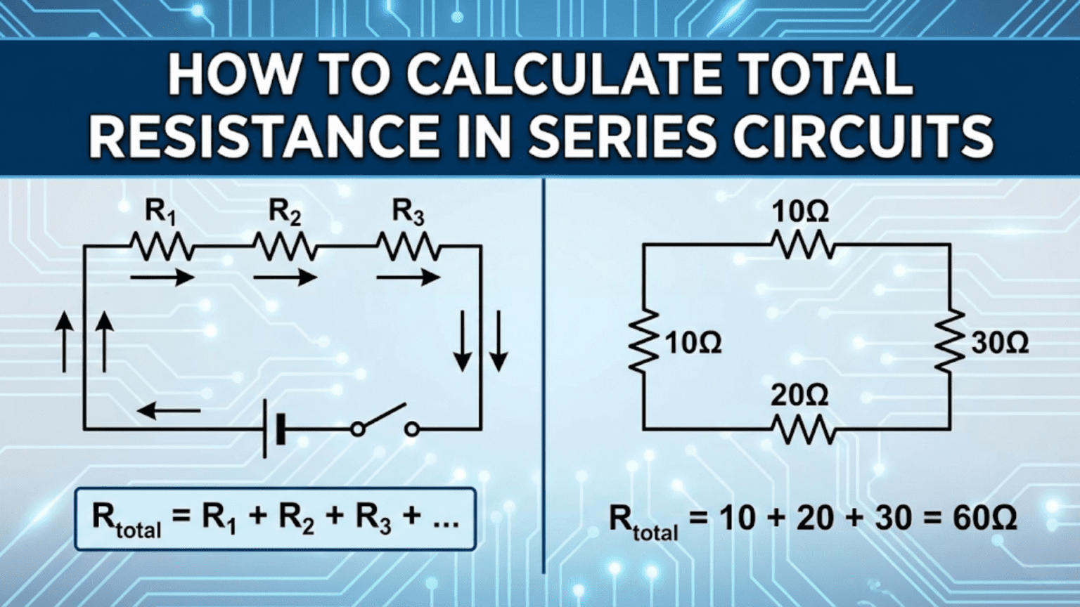
Calculating total resistance in series circuits involves simply adding the individual resistance values together: R_total = R₁ + R₂ + R₃ + … + Rₙ. This straightforward addition works because current flows through each resistor in sequence, encountering the resistance of each component cumulatively, making series circuits the simplest resistance calculation in electronics.
Introduction: The Simplest Circuit Configuration
Series circuits represent the most fundamental circuit configuration in electronics. When components are connected in series, they form a single path for current to flow—like cars on a one-lane road with no exits or entrances along the way. Understanding how to calculate total resistance in series circuits is one of the first essential skills every electronics enthusiast must master.
The beauty of series circuits lies in their simplicity. Unlike parallel circuits with their reciprocal formulas and complex current divisions, series circuits follow an elegantly straightforward rule: resistances simply add together. If you have a 100Ω resistor in series with a 220Ω resistor, your total resistance is 320Ω. No complex math, no special cases, just direct addition.
But don’t mistake simplicity for lack of importance. Series circuits appear everywhere in electronics: voltage dividers that scale down signals for microcontroller inputs, LED strings in holiday decorations, current-limiting circuits, sensor interfaces, battery configurations, and countless other applications. Even complex circuits contain series elements that must be analyzed using the principles we’ll explore in this article.
Beyond the basic calculation, understanding series circuits develops crucial intuition about how circuits behave. You’ll learn why adding resistance reduces current, how voltage distributes among components, where power dissipates, and how component tolerance affects overall circuit performance. These insights form the foundation for more advanced circuit analysis and design.
This comprehensive guide takes you from the fundamental concepts through practical applications. We’ll explore the mathematical basis for series resistance, work through numerous examples with different component types, examine real-world design scenarios, investigate common mistakes, and connect series resistance to broader circuit analysis techniques. Whether you’re calculating resistances for your first LED circuit or designing precision voltage references, this article provides the knowledge you need.
Let’s begin by understanding what makes a circuit “series” and why resistances add the way they do.
What Defines a Series Circuit?
The Essential Characteristic: Single Current Path
A series circuit is defined by one fundamental property: there is only one path for current to flow from the source, through all components, and back to the source.
Visual analogy: Imagine a string of beads on a thread. Current flows like sliding the beads along the thread—every bead must move for any to move. There’s no way for current to “skip” a component or take an alternate route.
Technical definition: Components are in series when:
- The same current flows through all of them
- They are connected end-to-end with no branches
- Removing any component breaks the entire circuit path
Contrast with parallel: In a parallel circuit, current has multiple paths. Like a highway with multiple lanes, traffic (current) can divide among different routes. Series circuits have no such division—it’s one lane, one path, all or nothing.
Identifying Series Components in Circuits
Simple series circuit: Battery → Resistor → Resistor → LED → back to Battery
All components share the same current because there’s nowhere else for the current to go.
Mixed circuit example: Consider a circuit where:
- Battery connects to Resistor A
- Resistor A connects to a junction
- At the junction, current splits to Resistor B and Resistor C (parallel)
- After B and C, current recombines and flows through Resistor D
- Resistor D returns to battery
Series components: Resistor A and Resistor D (same current flows through both) Parallel components: Resistors B and C (current divides between them)
Key insight: Even complex circuits contain series sections. Recognizing which components are in series is crucial for analysis.
Series Connections in Physical Circuits
On a breadboard: Components plugged into consecutive holes in the same row are in series (breadboard rows are internally connected).
On a PCB: Components connected by a trace with no other connections between them are in series.
In a schematic: Components connected by lines with no junction dots between them are in series.
Important caveat: Physical proximity doesn’t determine series connection—electrical connectivity does. Two components right next to each other on a breadboard might be in parallel if they connect to the same two rails.
Why the Same Current Flows Through Series Components
This is a consequence of charge conservation (Kirchhoff’s Current Law):
At any junction: Current in equals current out.
For series components: There are no junctions between them where current could split or combine, so the current that enters the first component must be the same current that exits the last component.
Mathematical proof: Consider three resistors in series: R₁ → R₂ → R₃
At the junction between R₁ and R₂: Current out of R₁ = Current into R₂ (only one path)
At the junction between R₂ and R₃: Current out of R₂ = Current into R₃ (only one path)
Therefore: I₁ = I₂ = I₃
Practical implication: If you measure 50mA through any component in a series circuit, you know with certainty that 50mA flows through every component in that series path.
The Series Resistance Formula: Why Resistances Add
The Basic Formula
For resistors in series, the total resistance is simply the sum of individual resistances:
R_total = R₁ + R₂ + R₃ + … + Rₙ
Where:
- R_total is the equivalent resistance of the entire series combination
- R₁, R₂, R₃, etc. are the individual resistor values
- n is the total number of resistors
Example: Three resistors in series: 100Ω, 220Ω, and 470Ω R_total = 100Ω + 220Ω + 470Ω = 790Ω
No reciprocals, no square roots, no complex formulas—just add them up.
Why This Works: The Physical Explanation
Resistance is opposition to current flow. When current must flow through multiple resistors in sequence, it encounters the opposition from each one:
Resistor analogy as obstacles: Imagine pushing a ball through a tube filled with progressively smaller mesh screens. The ball encounters resistance from the first screen, then the second, then the third. The total resistance is the cumulative effect of all screens.
Voltage perspective: Ohm’s Law states V = I × R. For series resistors with the same current I:
- Voltage across R₁: V₁ = I × R₁
- Voltage across R₂: V₂ = I × R₂
- Voltage across R₃: V₃ = I × R₃
Total voltage across all resistors: V_total = V₁ + V₂ + V₃ = I × R₁ + I × R₂ + I × R₃ = I × (R₁ + R₂ + R₃)
Since V_total = I × R_total: R_total = R₁ + R₂ + R₃
Energy perspective: Each resistor dissipates some electrical energy as heat. The total energy dissipated equals the sum of individual dissipations, which corresponds to the sum of resistances.
Mathematical Derivation Using Ohm’s Law
Given:
- Series circuit with voltage V applied
- Resistors R₁, R₂, R₃ in series
- Current I through all resistors (same current in series)
Step 1: Voltage drops V₁ = I × R₁ V₂ = I × R₂ V₃ = I × R₃
Step 2: Total voltage (Kirchhoff’s Voltage Law) V_total = V₁ + V₂ + V₃
Step 3: Substitute Ohm’s Law V_total = I × R₁ + I × R₂ + I × R₃
Step 4: Factor out current V_total = I × (R₁ + R₂ + R₃)
Step 5: Apply Ohm’s Law to total circuit V_total = I × R_total
Step 6: Equate I × R_total = I × (R₁ + R₂ + R₃)
Step 7: Solve for R_total R_total = R₁ + R₂ + R₃
This proves mathematically that series resistances add directly.
Important Properties of Series Resistance
Property 1: Total resistance is always greater than any individual resistor R_total > R₁ and R_total > R₂ and R_total > R₃, etc.
Adding resistance always increases total resistance—you can never make total resistance smaller by adding more series resistors.
Property 2: Order doesn’t matter R_total = R₁ + R₂ = R₂ + R₁ (commutative property)
You get the same total resistance whether you arrange resistors as 100Ω-220Ω-470Ω or 470Ω-100Ω-220Ω.
Property 3: Even one very large resistor dominates If you have 1Ω, 2Ω, and 1,000,000Ω in series: R_total = 1,000,003Ω ≈ 1,000,000Ω
The largest resistor essentially determines the total resistance.
Property 4: Units must be consistent You must convert all resistances to the same unit before adding. Don’t add 1kΩ + 100Ω + 1MΩ directly—convert to ohms first: 1,000Ω + 100Ω + 1,000,000Ω = 1,001,100Ω.
Step-by-Step: Calculating Series Resistance
Basic Calculation Process
Step 1: Identify all series resistors Trace the current path and list all resistors that the same current flows through.
Step 2: Note each resistor value Write down R₁, R₂, R₃, etc. with their units.
Step 3: Convert to consistent units If resistors are given in kΩ, MΩ, or other units, convert all to ohms (Ω).
Step 4: Add the values R_total = R₁ + R₂ + R₃ + …
Step 5: Express in convenient units If R_total = 47,000Ω, you can write it as 47kΩ for convenience.
Example 1: Simple Two-Resistor Series
Given:
- R₁ = 1,000Ω (1kΩ)
- R₂ = 2,200Ω (2.2kΩ)
Calculation: R_total = R₁ + R₂ = 1,000Ω + 2,200Ω = 3,200Ω = 3.2kΩ
Verification: If V = 16V is applied: I = V ÷ R_total = 16V ÷ 3,200Ω = 0.005A = 5mA
Voltage across R₁: V₁ = I × R₁ = 5mA × 1kΩ = 5V Voltage across R₂: V₂ = I × R₂ = 5mA × 2.2kΩ = 11V Total: V₁ + V₂ = 5V + 11V = 16V ✓
Example 2: Multiple Resistors with Different Units
Given:
- R₁ = 100Ω
- R₂ = 2.2kΩ
- R₃ = 47kΩ
- R₄ = 0.1MΩ
Step 1: Convert to ohms
- R₁ = 100Ω
- R₂ = 2,200Ω
- R₃ = 47,000Ω
- R₄ = 100,000Ω
Step 2: Add R_total = 100 + 2,200 + 47,000 + 100,000 = 149,300Ω
Step 3: Express in convenient units R_total = 149.3kΩ ≈ 150kΩ
Observation: The 100Ω resistor contributes only 0.067% of the total resistance. R₄ dominates.
Example 3: Resistor Color Code Series
Given: Three resistors with color codes:
- Resistor 1: Brown-Black-Red (1-0-×100 = 1,000Ω = 1kΩ)
- Resistor 2: Red-Red-Orange (2-2-×1000 = 22,000Ω = 22kΩ)
- Resistor 3: Yellow-Violet-Red (4-7-×100 = 4,700Ω = 4.7kΩ)
Calculation: R_total = 1kΩ + 22kΩ + 4.7kΩ = 27.7kΩ
Selecting a replacement: If you need to replace this three-resistor series with a single resistor, use a 27kΩ (closest standard value) or 30kΩ (next higher standard value for safety margin).
Example 4: LED Circuit with Current-Limiting Resistor
Given: LED circuit from 9V battery:
- LED forward voltage drop: 2V (not a resistor, but acts like voltage drop)
- Current-limiting resistor: R = ?
- Desired current: 20mA
Analysis: This isn’t a “pure” series resistance calculation because LEDs aren’t ohmic resistors. However, we can analyze it using series circuit principles.
Step 1: Voltage across resistor V_resistor = V_supply – V_LED = 9V – 2V = 7V
Step 2: Calculate required resistance R = V ÷ I = 7V ÷ 0.020A = 350Ω
Use standard 360Ω or 390Ω resistor.
Step 3: If adding another resistor in series Suppose you only have 270Ω resistors. How many do you need? R_total needed ≈ 350Ω Number of 270Ω resistors: 350 ÷ 270 ≈ 1.3
Use two resistors: 2 × 270Ω = 540Ω (current will be lower, LED dimmer but safer)
Example 5: Precision Voltage Reference
Given: You need exactly 5.750kΩ but only have standard resistor values.
Available resistors: 5.6kΩ, 150Ω, 100Ω, 47Ω, 10Ω, 1Ω
Solution using series combination: 5.6kΩ + 150Ω = 5,750Ω = 5.750kΩ (exact!)
Alternative if 5.6kΩ unavailable: 4.7kΩ + 1kΩ + 47Ω + 3Ω = 5,750Ω
More resistors mean more tolerance stack-up, but this works if needed.
Practical Applications of Series Resistance
Application 1: Voltage Dividers
Purpose: Scale down a voltage to a desired level.
Circuit: Two resistors in series across a voltage source. Output taken from the junction.
Example: Scale 12V down to 5V for a microcontroller ADC input:
Design: V_out = V_in × (R₂ ÷ (R₁ + R₂)) 5V = 12V × (R₂ ÷ (R₁ + R₂)) R₂ ÷ (R₁ + R₂) = 5/12 ≈ 0.417
Choose R₂ = 10kΩ (convenient value) 10kΩ ÷ (R₁ + 10kΩ) = 0.417 10kΩ = 0.417 × (R₁ + 10kΩ) 10kΩ = 0.417R₁ + 4.17kΩ 5.83kΩ = 0.417R₁ R₁ ≈ 14kΩ
Series resistance: R_total = R₁ + R₂ = 14kΩ + 10kΩ = 24kΩ
This total determines current draw: I = 12V ÷ 24kΩ = 0.5mA (low power consumption).
Application 2: LED Strings for Decorative Lighting
Scenario: Christmas lights with multiple LEDs in series.
Example: 120V AC (rectified to ~170V DC peak) powering 50 white LEDs in series:
- Each LED: V_f = 3.2V
- Total LED voltage drop: 50 × 3.2V = 160V
- Remaining voltage for current-limiting resistor: 170V – 160V = 10V
- Desired current: 20mA
Series resistance calculation: R = V ÷ I = 10V ÷ 0.020A = 500Ω
Total circuit resistance: The LEDs plus resistor form a series circuit. While LEDs aren’t pure resistors, the total current-limiting effect comes from the 500Ω resistor plus the dynamic resistance of the LED string.
Practical consideration: If one LED fails open, the entire string goes dark (series circuit property). This is why LED strings often have shunt resistors across each LED for fault tolerance.
Application 3: Current Sensing with Shunt Resistors
Purpose: Measure current by measuring voltage drop across a small series resistor.
Example: Monitor current in a 12V circuit that draws 0-5A:
Design: Use a low-value shunt resistor in series with the load: R_shunt = 0.1Ω (100 milliohms)
Voltage drop at maximum current: V_shunt = I × R = 5A × 0.1Ω = 0.5V
Why series? The shunt must be in series with the load so the same current flows through both. This allows accurate current measurement.
Total circuit resistance: If load resistance is 2.4Ω: R_total = R_load + R_shunt = 2.4Ω + 0.1Ω = 2.5Ω
The shunt adds only 4% to total resistance, minimally affecting circuit operation.
Application 4: Resistor Networks for Calibration
Purpose: Create precise resistance values by combining standard resistors.
Example: Calibrating a Wheatstone bridge requires 10.000kΩ ± 0.01%:
Available: 0.1% tolerance resistors in standard values
Solution: Use series combination of high-precision resistors:
- 8.2kΩ (0.1% tolerance)
- 1.5kΩ (0.1% tolerance)
- 300Ω (0.1% tolerance)
R_total = 8,200Ω + 1,500Ω + 300Ω = 10,000Ω
Tolerance analysis: Worst case (all tolerances add): Max: 8,208.2Ω + 1,501.5Ω + 300.3Ω = 10,010Ω (+0.1%) Min: 8,191.8Ω + 1,498.5Ω + 299.7Ω = 9,990Ω (-0.1%)
Meets specification!
Application 5: Impedance Matching in Audio Circuits
Purpose: Match source and load impedances for maximum power transfer.
Example: Amplifier output impedance is 4Ω. Speaker is 8Ω. Add series resistance to approximate 8Ω source impedance for damping factor control.
Calculation: R_series + R_source = R_desired R_series + 4Ω = 8Ω R_series = 4Ω
Total series resistance in speaker path: R_total = R_amp + R_series = 4Ω + 4Ω = 8Ω
Effect: This modifies the damping factor and frequency response. While not always desirable, it illustrates how series resistance can be used for impedance control.
Application 6: Battery String Configuration
Purpose: Increase voltage by series-connecting batteries.
Example: Four 1.5V AA batteries in series (flashlight configuration):
Total voltage: V_total = V₁ + V₂ + V₃ + V₄ = 1.5V + 1.5V + 1.5V + 1.5V = 6V
Internal resistance: Each battery has internal resistance of approximately 0.2Ω:
Total internal resistance: R_internal_total = 0.2Ω + 0.2Ω + 0.2Ω + 0.2Ω = 0.8Ω
This internal resistance is in series with the load, affecting available current: If load is 5.2Ω: R_total = R_load + R_internal = 5.2Ω + 0.8Ω = 6Ω I = V ÷ R = 6V ÷ 6Ω = 1A
Voltage at load: V_load = I × R_load = 1A × 5.2Ω = 5.2V (not 6V due to internal resistance drop)
Series Resistance with Different Component Types
Resistors: The Pure Case
Standard resistors: Carbon film, metal film, wirewound—all follow the simple addition rule perfectly.
Example: 470Ω + 1kΩ + 2.2kΩ = 3,670Ω (exactly)
Considerations:
- Tolerance: ±1%, ±5%, ±10% (affects actual value)
- Temperature coefficient: Resistance changes with temperature
- Power rating: Each resistor must handle its power dissipation
Resistors + LEDs
LEDs in series: Each LED drops a fixed forward voltage (approximately constant for a given current range).
Equivalent series resistance perspective: While LEDs aren’t pure resistors, they contribute to total circuit impedance.
Example calculation: 3 LEDs in series (V_f = 2V each) with 330Ω resistor from 12V:
Voltage distribution: V_LEDs = 3 × 2V = 6V V_resistor = 12V – 6V = 6V
Current: I = V_resistor ÷ R = 6V ÷ 330Ω ≈ 18.2mA
The resistor provides the “true” resistance; LEDs provide voltage drops.
Resistors + Switches
Closed switch: Ideally zero resistance, but actually ~0.01-0.1Ω (contact resistance).
Example: 1kΩ resistor in series with switch (R_switch ≈ 0.05Ω): R_total = 1,000Ω + 0.05Ω ≈ 1,000Ω (switch resistance negligible)
Open switch: Infinite resistance, breaks circuit completely.
Practical note: Switch contact resistance matters in low-resistance, high-current circuits. In a 1Ω circuit carrying 10A, a 0.1Ω switch adds 10% resistance!
Resistors + Wires
Wire resistance: Often neglected but sometimes significant.
Example: Copper wire, 22 AWG, 10 feet (3.05m) long: Resistance per meter: ~0.053Ω/m Wire resistance: 3.05m × 0.053Ω/m ≈ 0.162Ω
For a circuit with 100Ω resistance, this adds ~0.16% (negligible). For a circuit with 1Ω resistance, this adds ~16% (significant!).
Total series resistance including wire: R_total = R_component + R_wire
Resistors + Inductors (DC Analysis)
DC resistance: Inductors have wire resistance (DC resistance) in addition to inductance.
Example: 1H inductor with 50Ω DC resistance in series with 470Ω resistor:
For DC analysis (steady state): R_total = 470Ω + 50Ω = 520Ω
For AC analysis: Must consider inductive reactance (X_L = 2πfL) in addition to resistance, giving impedance (covered in advanced courses).
Resistors + Capacitors (DC Analysis)
Capacitors: Act as open circuits for DC (infinite resistance after initial charging).
Example: 100Ω resistor in series with capacitor:
During charging transient: Current flows, resistor limits charging rate (RC time constant).
After full charge (DC steady state): No current flows (capacitor blocks DC).
Effective DC resistance: Infinite (open circuit)
Potentiometers: Variable Series Resistance
Potentiometer: Variable resistor with three terminals. Can function as series variable resistance.
Example: 10kΩ potentiometer set to 40% position in series with 5kΩ fixed resistor:
Potentiometer resistance (in series configuration): R_pot = 0.40 × 10kΩ = 4kΩ
Total series resistance: R_total = 5kΩ + 4kΩ = 9kΩ
As potentiometer adjusts from 0-100%, R_total varies from 5kΩ to 15kΩ.
Common Mistakes and How to Avoid Them
Mistake 1: Confusing Series and Parallel
Error: Adding resistances that are actually in parallel, or vice versa.
Example of error: Two 100Ω resistors in parallel, calculated as: 100Ω + 100Ω = 200Ω (wrong!)
Correct calculation: Parallel: R_total = (100Ω × 100Ω) ÷ (100Ω + 100Ω) = 50Ω
How to avoid:
- Trace the current path carefully
- Ask: “Does current split?” If yes, it’s parallel
- Ask: “Does the same current flow through both?” If yes, it’s series
- Draw the circuit yourself before calculating
Mistake 2: Unit Inconsistency
Error: Adding resistances with different units without converting.
Example of error: 1kΩ + 100Ω + 2.2MΩ = 3.3? (units don’t match!)
Correct approach: Convert to ohms: 1,000Ω + 100Ω + 2,200,000Ω = 2,201,100Ω = 2.2011MΩ
How to avoid:
- Always convert to base unit (ohms) before calculating
- Or work consistently in one prefix unit (all kΩ or all MΩ)
- Double-check unit labels
Mistake 3: Forgetting Parasitic Resistances
Error: Ignoring wire resistance, contact resistance, or component lead resistance.
When it matters:
- Low-resistance circuits (< 10Ω)
- High-current circuits (> 1A)
- Precision measurements
- Long wire runs
Example: Calculating current in a 2Ω circuit with 12V: Naive: I = 12V ÷ 2Ω = 6A
But if wire resistance is 0.5Ω total: Actual: I = 12V ÷ (2Ω + 0.5Ω) = 12V ÷ 2.5Ω = 4.8A (20% error!)
How to avoid:
- Consider wire gauge and length
- Account for connector and switch contact resistance
- Include internal resistance of voltage sources
- For precision work, measure actual total resistance
Mistake 4: Incorrect Tolerance Stack-Up
Error: Assuming series combination has same tolerance as individual components.
Reality: Tolerances can add in worst case.
Example: Three 10kΩ ±5% resistors in series:
Nominal: 30kΩ
Worst case maximum: Each could be 10.5kΩ: 3 × 10.5kΩ = 31.5kΩ (+5% from nominal)
Worst case minimum: Each could be 9.5kΩ: 3 × 9.5kΩ = 28.5kΩ (-5% from nominal)
Tolerance range: ±1.5kΩ (±5% of 30kΩ)
The percentage tolerance stays the same, but absolute uncertainty increases.
How to avoid:
- Use tighter tolerance resistors for critical circuits
- Measure and select resistors for precision applications
- Design circuits to be tolerant of component variation
Mistake 5: Power Rating Oversight
Error: Checking total power but not individual resistor power dissipation.
Example: Two resistors in series: 100Ω and 900Ω across 100V R_total = 1000Ω I = 100V ÷ 1000Ω = 0.1A = 100mA P_total = V × I = 100V × 0.1A = 10W
“Okay, I’ll use 10W resistors…”
But check individual power: P₁ = I² × R₁ = (0.1A)² × 100Ω = 1W P₂ = I² × R₂ = (0.1A)² × 900Ω = 9W
The 900Ω resistor dissipates 9W! If you used two 10W resistors, the 900Ω one operates near its limit (dangerous). Better to use 2W for 100Ω and 15W for 900Ω.
How to avoid:
- Calculate power for EACH resistor: P = I² × R
- Derate to 50-75% of maximum rating
- Verify thermal management
Mistake 6: Assuming Order Doesn’t Affect Voltage Distribution
Error: Thinking resistor order matters for voltage division in series.
Clarification: Order doesn’t affect TOTAL resistance, but it affects where voltages appear.
Example: 12V source with 1kΩ and 2kΩ in series:
Configuration 1: Source → 1kΩ → 2kΩ → Ground Voltage at junction: 8V (2kΩ portion gets 8V, 1kΩ portion gets 4V)
Configuration 2: Source → 2kΩ → 1kΩ → Ground Voltage at junction: 4V (1kΩ portion gets 4V, 2kΩ portion gets 8V)
Total resistance: Same (3kΩ) in both cases Voltage at specific points: Different!
How to avoid confusion:
- Remember: R_total is independent of order
- Remember: Voltage distribution depends on order
- Label your circuit nodes clearly
Mistake 7: Using Damaged or Wrong-Value Components
Error: Installing a resistor without verifying its value.
Real-world scenario: A 1kΩ resistor gets overheated and changes to 1.2kΩ. You measure the series combination and wonder why it’s higher than expected.
How to avoid:
- Measure resistors before installation
- Check color codes carefully (brown-black-red is 1kΩ, not 100Ω!)
- Test circuits after assembly
- Replace any resistor that gets hot
Advanced Topics: Series Resistance in Complex Scenarios
Temperature Effects on Series Resistance
Temperature coefficient: Resistance changes with temperature.
For metal film resistors: Typical coefficient ~±50 ppm/°C (parts per million)
Example: Three 10kΩ resistors in series at 25°C: R_total(25°C) = 30kΩ
At 75°C (50°C rise): Each resistor changes by: 10,000Ω × 50 × 10⁻⁶ × 50°C = 25Ω New value per resistor: 10,025Ω R_total(75°C) = 3 × 10,025Ω = 30,075Ω
Change: 75Ω increase (0.25%)
For precision circuits: This matters! Use low-temperature-coefficient resistors or temperature compensation.
Series Resistance in AC Circuits
For pure resistors in AC: The series addition rule still applies for resistance.
However: AC circuits often include reactive components (capacitors, inductors).
Impedance (Z) in series: Z_total = Z₁ + Z₂ + Z₃ + …
Where Z can be complex (Z = R + jX, with R = resistance, X = reactance).
Example: Resistor (100Ω) in series with inductor (50Ω resistance + j377Ω reactance at 60Hz):
Z_total = (100 + j0) + (50 + j377) = 150 + j377Ω
Magnitude: |Z| = √(150² + 377²) ≈ 406Ω
This is beyond pure resistance, but shows how series concepts extend to AC.
Nonlinear Components in Series
Thermistors: Resistance varies with temperature (often significantly).
Example: NTC thermistor (10kΩ at 25°C) in series with 10kΩ fixed resistor:
At 25°C: R_total = 20kΩ At 50°C: Thermistor drops to 4kΩ, R_total = 14kΩ At 0°C: Thermistor rises to 30kΩ, R_total = 40kΩ
The total series resistance varies with temperature, which is the basis for temperature sensing circuits.
Varistors (VDRs): Resistance varies with voltage.
These components don’t follow simple addition rules except at a specific operating point.
Series Resistance in Digital Circuits
Pull-up/pull-down resistors: Series resistors that set default logic levels.
Example: Microcontroller input with 10kΩ pull-up to 5V and button to ground:
Button open: Input “sees” 10kΩ to 5V (logic HIGH) Button closed: 10kΩ in series with closed switch (~0Ω) to ground
The series resistance limits current when button is pressed: I = 5V ÷ 10kΩ = 0.5mA (safe, low current)
Series termination resistors: Match impedance in digital signal lines.
Example: 33Ω resistor in series with microcontroller output to PCB trace:
This resistor is in series with the transmission line impedance, providing impedance matching to reduce reflections in high-speed signals.
Design Strategies Using Series Resistance
Strategy 1: Creating Custom Resistance Values
Problem: Need 3.7kΩ but only have E12 series resistors.
Solution: Combine standard values in series: 3.3kΩ + 390Ω = 3,690Ω ≈ 3.7kΩ or 3.3kΩ + 330Ω + 47Ω = 3,677Ω ≈ 3.68kΩ
Consideration: More resistors mean more tolerance stack-up and more board space.
Strategy 2: Power Distribution
Problem: Single resistor can’t handle required power dissipation.
Solution: Split power among multiple series resistors.
Example: Need 1kΩ resistor to dissipate 10W:
A single 1kΩ 10W resistor might be large, expensive, or unavailable.
Alternative: Use ten 100Ω 1W resistors in series: R_total = 10 × 100Ω = 1,000Ω ✓ P_each = 10W ÷ 10 = 1W per resistor ✓
Each resistor handles 1W (within rating), and 1W resistors are cheaper and more available.
Strategy 3: Voltage Rating Considerations
Problem: Applied voltage exceeds resistor voltage rating.
Example: 500V across a resistor (but most resistors rated for 200-250V maximum).
Solution: Use series resistors to divide voltage: Five 100kΩ resistors in series: R_total = 500kΩ V_each = 500V ÷ 5 = 100V per resistor (safe!)
Strategy 4: Adjustable Resistance
Problem: Need adjustable resistance for tuning or calibration.
Solution: Fixed resistor in series with potentiometer.
Example: Need 8-12kΩ adjustable range:
- Fixed: 8kΩ
- Variable: 5kΩ potentiometer (set from 0-100%)
R_total = 8kΩ + (0 to 5kΩ) = 8kΩ to 13kΩ (close to target range)
Alternatively:
- Fixed: 7.5kΩ
- Variable: 5kΩ pot R_total = 7.5kΩ to 12.5kΩ (better centered on 8-12kΩ range)
Strategy 5: Current Limiting with Precision
Problem: Limit current to exact value with available resistors.
Example: Need to limit current to exactly 15.0mA at 12V:
Required R = V ÷ I = 12V ÷ 0.015A = 800Ω
Available standard values: 680Ω, 820Ω, 100Ω, 120Ω
Series solution: 680Ω + 120Ω = 800Ω (exact!)
Comparison Table: Series vs. Parallel Resistance
| Aspect | Series Resistance | Parallel Resistance |
|---|---|---|
| Formula | R_total = R₁ + R₂ + R₃ + … | 1/R_total = 1/R₁ + 1/R₂ + 1/R₃ + … |
| Calculation complexity | Simple addition | Reciprocals (more complex) |
| Current through components | Same through all components | Divides among components |
| Voltage across components | Divides among components | Same across all components |
| Total R vs. individual R | Always greater than largest | Always less than smallest |
| Adding more resistors | Increases total resistance | Decreases total resistance |
| Two equal resistors (R) | R_total = 2R | R_total = R/2 |
| Power distribution | Unequal (proportional to resistance) | Unequal (inversely proportional to resistance) |
| Failure mode | One open = all fail | One short = bypasses others |
| Common applications | Voltage dividers, current limiting, battery strings | Current dividers, reduced resistance, redundancy |
| Circuit behavior | Single path for current | Multiple paths for current |
| Design strategy | Use to increase resistance or divide voltage | Use to decrease resistance or divide current |
Practical Measurement and Verification
Measuring Series Resistance
Method 1: Direct measurement Use an ohmmeter across the entire series combination:
Process:
- Remove circuit from power
- Disconnect at least one end from the rest of circuit
- Measure resistance across the combination
- Compare to calculated value
Expected agreement: Within component tolerance (typically ±5%)
Method 2: Individual measurement and addition Measure each resistor separately, then add:
Advantage: Identifies any out-of-tolerance or damaged components Disadvantage: Doesn’t catch connection problems
Verifying with Current and Voltage
Method 3: Operational verification With circuit powered:
- Measure voltage across entire series combination
- Measure current through series combination
- Calculate R_total = V ÷ I
- Compare to expected value
Example: Three resistors in series (100Ω + 220Ω + 470Ω = 790Ω expected)
Measured: V = 7.9V, I = 10mA Calculated: R = 7.9V ÷ 0.010A = 790Ω ✓
Troubleshooting Discrepancies
If measured R_total is higher than expected:
- Open connection somewhere
- Wrong resistor value installed
- Corroded contacts adding resistance
- Wire resistance significant
If measured R_total is lower than expected:
- Short circuit somewhere
- Resistor value lower than marked
- Solder bridge creating parallel path
- Wrong resistor installed
Systematic diagnosis:
- Measure each resistor individually
- Check solder joints and connections
- Verify resistor color codes or markings
- Test for shorts with continuity tester
Conclusion: Mastering Series Resistance
Understanding how to calculate total resistance in series circuits is a foundational skill that every electronics enthusiast must master. While the mathematics are beautifully simple—just add the values together—the applications and implications extend throughout all of electronics.
Key Takeaways
The fundamental rule: For resistors in series, R_total = R₁ + R₂ + R₃ + … This simple addition works because current must flow through each resistor sequentially, encountering each resistance cumulatively.
Same current, divided voltage: Series circuits are characterized by identical current through all components, with voltage dividing among them proportional to their resistances.
Practical applications: From voltage dividers to LED strings, from current sensing to battery configurations, series resistance appears everywhere in electronics.
Design flexibility: By combining standard resistor values in series, you can create virtually any resistance value needed for your designs.
Power considerations: Remember to calculate power dissipation for each individual resistor, not just the total. Each component must be rated for its specific power.
Beyond the Basics
While this article focused on simple series calculations, the concepts extend to:
- Complex circuits: Identifying series sections within larger circuits
- AC circuits: Where impedance (combining resistance and reactance) follows similar series rules
- Temperature-dependent systems: Where resistance varies with operating conditions
- Precision applications: Where tolerance stack-up and parasitic resistances matter
Integration with Circuit Analysis
Series resistance calculations don’t exist in isolation—they integrate with:
- Ohm’s Law: V = I × R applies to each resistor and the total series combination
- Kirchhoff’s Voltage Law: Voltages around a series loop sum to zero
- Power calculations: P = I² × R for each component, P_total = sum of individual powers
- Circuit simplification: Replacing series combinations with equivalent single resistors
Moving Forward
Now that you understand series resistance:
- Practice with real circuits: Build series combinations and verify calculations with measurements
- Apply to designs: Use series resistance in voltage dividers, current limiters, and other practical circuits
- Study parallel resistance: Learn the complementary concept of how parallel resistors combine
- Explore combination circuits: Master analyzing circuits with both series and parallel sections
- Advance to complex analysis: Apply these fundamentals to real-world circuit design and troubleshooting
Final Thoughts
The elegance of series resistance lies in its simplicity. While parallel resistance requires reciprocal formulas and parallel circuit analysis involves current division, series circuits follow the most intuitive rule possible: resistances simply add.
This simplicity doesn’t diminish importance. Whether you’re calculating the resistance of a simple voltage divider or analyzing the complex series-parallel networks in a power distribution system, understanding series resistance is essential.
Every complex circuit can be broken down into combinations of series and parallel sections. Master series resistance calculations, and you’ve taken a crucial step toward mastering circuit analysis as a whole.
From your first LED circuit with a current-limiting resistor to sophisticated precision measurement systems, series resistance will be your constant companion in electronics. Embrace this fundamental concept, practice applying it in diverse situations, and watch as circuit behavior becomes increasingly intuitive.
The path to electronics mastery is built one fundamental concept at a time. Series resistance—with its simple addition rule and profound implications—represents one of the most important building blocks on that path.
R_total = R₁ + R₂ + R₃ + …
Simple formula. Universal application. Foundation of circuit analysis.