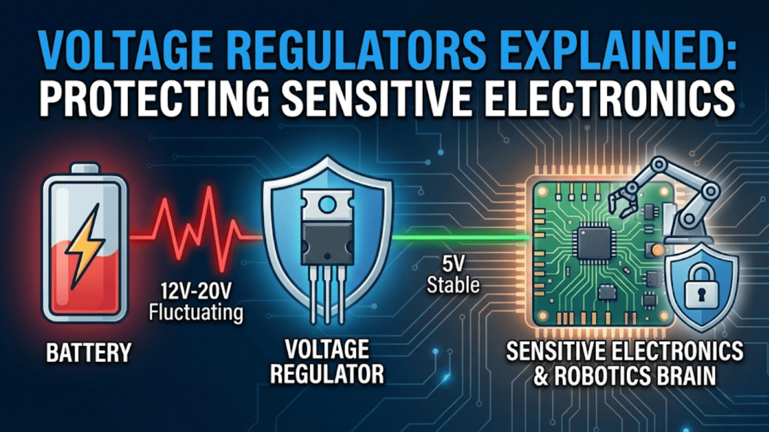
A voltage regulator is a circuit that takes an unregulated, varying input voltage—such as a discharging battery that drops from 12.6V to 9.0V over a run—and produces a stable, precise output voltage that sensitive electronics require to function correctly, with two main types in robotics: linear regulators (LDOs), which are simple, quiet, and accurate but waste excess voltage as heat, making them suitable only for low-current applications with small voltage differences; and switching regulators (buck converters), which efficiently convert high voltage to lower voltage with 85–95% efficiency but introduce switching noise that must be managed in sensitive analog and RF circuits.
Every electronic component in your robot has a required operating voltage. Your Arduino Uno needs 5V. Your Raspberry Pi needs exactly 5.1V. Your IMU sensor runs on 3.3V. Your Bluetooth module wants 3.3V. But your battery—a 3S LiPo—produces anywhere from 9.0V (nearly depleted) to 12.6V (fully charged), varying continuously throughout every run.
If you connected any of those components directly to the battery, the results would range from immediate destruction (the 3.3V sensor connected to 12.6V) to erratic behavior (the Arduino seeing 11V when it expects 5V) to gradual degradation (components operated continuously above their rated voltage). None of these outcomes is acceptable in a robot that needs to work reliably.
Voltage regulators solve this problem by acting as precision voltage converters—taking whatever the battery provides and delivering a stable, component-appropriate voltage regardless of the battery state. They’re not glamorous, and they rarely receive the attention given to motors or microcontrollers, but they are as fundamental to robot reliability as the battery itself.
Understanding voltage regulators—how each type works, what its limitations are, how to select and size one correctly, and how to implement it in a robot power system—is an essential skill for any robot builder beyond the beginner stage. This article provides that complete understanding.
Why Regulated Voltage Matters
Before exploring how regulators work, it’s worth establishing precisely why stable voltage is so critical to electronic components.
Digital Logic Thresholds
Digital circuits—microcontrollers, logic ICs, communication modules—operate by distinguishing HIGH voltage levels from LOW voltage levels. These thresholds are defined relative to the supply voltage (VCC). A 5V logic system defines HIGH as above approximately 0.7 × VCC = 3.5V and LOW as below approximately 0.3 × VCC = 1.5V.
If the supply voltage fluctuates—say, sagging to 4.2V when a motor starts—the thresholds shift accordingly, and signals that were cleanly HIGH or LOW may fall into the undefined region. The result is unpredictable logic behavior: false triggers, missed pulses, communication errors, and data corruption.
Analog Reference Accuracy
Analog-to-digital converters (ADCs) compare an input voltage to a reference voltage. If the ADC uses the supply voltage as its reference (common in microcontrollers like the Arduino), supply voltage fluctuations directly corrupt ADC readings. A 10% drop in supply voltage appears as a 10% error in every analog measurement—temperature readings, battery voltage measurements, distance calculations from analog sensors, all become inaccurate in proportion to supply voltage error.
Component Absolute Maximum Ratings
Every electronic component has an absolute maximum supply voltage—exceeding it causes immediate damage. A 3.3V sensor with a 3.6V maximum rating will be destroyed instantly if connected to a 5V supply without regulation, and will gradually degrade if operated at 4V. Voltage regulation isn’t just about proper operation—it’s about component survival.
Communication Timing
High-speed communication protocols (SPI at 8 MHz, USB, high-speed I2C) depend on precise signal timing. When supply voltage fluctuates, the propagation delay through logic gates changes, causing timing violations that corrupt data transfers at high speed. Stable supply voltage is a prerequisite for reliable high-speed digital communication.
Linear Regulators: Simple, Quiet, and Inefficient
The simplest type of voltage regulator is the linear regulator, so called because its output transistor operates in the linear (active) region—neither fully on nor fully off, but partially conducting to control the output voltage.
How Linear Regulators Work
A linear regulator works by placing a controllable series resistance between input and output. A feedback circuit continuously monitors the output voltage and adjusts the series element’s resistance to keep the output exactly at the target voltage:
     Input voltage (Vin)
          │
          ▼
    ┌─────────────┐
    │  Series     │  ← Variable resistance, controlled by feedback
    │  Pass       │
    │  Element    │
    └──────┬──────┘
           │
           ├──────────────── Output voltage (Vout, regulated)
           │
    ┌──────▼──────┐
    │  Feedback   │  ← Compares Vout to reference, adjusts pass element
    │  & Ref      │
    └─────────────┘
           │
GNDThe output voltage is determined by a precise internal voltage reference and resistor divider. For fixed-voltage regulators (the most common in robotics—7805 for 5V, AMS1117-3.3 for 3.3V), this divider is internal and fixed. For adjustable regulators (LM317, LM350), external resistors set the output voltage.
The Fundamental Limitation: Heat Dissipation
The critical limitation of linear regulators is their efficiency. Because the series pass element is a resistor-like element, all voltage that needs to be “dropped” from input to output is dissipated as heat:
Power dissipated as heat = (Vin - Vout) × Iout

Example: 5V regulator (LM7805) running from a 12V battery at 500mA
Heat dissipated = (12V - 5V) × 0.5A = 7V × 0.5A = 3.5W

Efficiency = Pout / Pin = (5V × 0.5A) / (12V × 0.5A) = 2.5W / 6W = 41.7%

That 3.5W of heat must go somewhere — it heats the regulator package,
which must be heat-sinked appropriately or it will overheat and shut down.For the LM7805, the maximum junction temperature is 125°C. Without a heatsink, a small TO-220 package has a thermal resistance of about 50°C/W. At 3.5W dissipation:
Temperature rise = 3.5W × 50°C/W = 175°C above ambient

At 25°C ambient: junction temperature = 25 + 175 = 200°C >> 125°C limit
→ Immediate thermal shutdown without a heatsink!

With adequate heatsink (5°C/W thermal resistance):
Temperature rise = 3.5W × 5°C/W = 17.5°C above ambient
Junction temperature = 25 + 17.5 = 42.5°C → safeThis calculation illustrates why linear regulators powering significant current loads need heatsinks—and why using a linear regulator to drop from 12V to 5V at even moderate currents is thermally impractical without serious thermal management.
Low-Dropout (LDO) Regulators
Standard linear regulators like the LM7805 require a minimum voltage difference (dropout voltage) between input and output—typically 2–3V—to maintain regulation. If the input drops to within 2V of the output, the regulator loses control of the output voltage and it drops below the target.
Low-Dropout (LDO) regulators use a different pass element topology (typically a PMOS transistor) that requires only 100–500mV of headroom to maintain regulation. This is important when the input-output voltage difference is small:
Example: Regulating from a 6-cell NiMH pack (7.2V nominal, down to 6.0V near empty)
to 5V output

Standard LM7805 (2.5V dropout): needs Vin > 7.5V to regulate → fails at 6.0V!
AMS1117-5 LDO (1.3V dropout):   needs Vin > 6.3V → barely maintains at end of discharge
MIC5219 LDO (0.5V dropout): needs Vin > 5.5V → safe throughout dischargeLDO selection matters particularly in battery-powered systems where the battery voltage closely approaches the regulated output voltage at end of discharge. Using a standard regulator in such a system causes the output voltage to droop before the battery is actually depleted, shortening effective run time.
Common Linear Regulators in Robotics
LM7805 / LM7812 / LM7833 series: The original workhorse linear regulators. Fixed output voltages (7805 = 5V, 7812 = 12V, 7833 = 3.3V). TO-220 package. 1.5A maximum output current. 2–3V dropout voltage. Still widely used for low-current 5V and 3.3V supplies. Requires heatsink above ~500mA in typical robotics voltage scenarios.
AMS1117 series (AMS1117-3.3, AMS1117-5.0): Popular LDO available in SOT-223 and TO-252 packages. 1A maximum output current. 1.3V dropout voltage. Used extensively on Arduino boards and many sensor modules for 3.3V regulation. Adequate for low-current sensor supplies; marginal for single-board computers at high load.
MIC5219 / AP2112 / XC6206 series: Modern, low-quiescent-current LDOs. 300–800mA output. Very low dropout (100–300mV). Excellent for battery-powered low-current applications where quiescent current affects standby battery life.
LM317 (adjustable): The classic adjustable linear regulator. Output voltage set by two external resistors. 1.5A maximum. Useful when a non-standard voltage is needed and a fixed LDO isn’t available. Dropout is 3V minimum—not suitable for battery-close-to-output-voltage applications.
LM317 output voltage calculation:
Vout = 1.25V × (1 + R2/R1)

For 5V output:
5V = 1.25V × (1 + R2/R1)
4 = 1 + R2/R1
R2/R1 = 3

Example values: R1 = 240Ω, R2 = 720Ω (or 680Ω for ~4.8V, close enough)When Linear Regulators Are the Right Choice
Despite their efficiency limitations, linear regulators are the correct choice in several important robotics scenarios:
Low current, small voltage drop. Supplying 50mA at 3.3V from a 5V rail: dropout = 1.7V × 0.05A = 85mW dissipated. Negligible heat, no heatsink needed, and the simplicity of an LDO is valuable.
Noise-sensitive analog circuits. Switching regulators generate high-frequency electrical noise (switching transients at their operating frequency, typically 100kHz–2MHz). This noise can corrupt precision analog signals, ADC readings, and RF communications. LDOs produce only thermal noise—orders of magnitude quieter. For powering precision ADC reference voltages, audio circuits, RF front ends, and high-resolution sensor supplies, LDO regulators are strongly preferred over switching regulators.
Tight output voltage tolerance. Some precision LDOs maintain output voltage to ±0.5% accuracy across temperature and load. High-quality switching regulators typically achieve ±2–3% without careful compensation. For precision analog circuits requiring tight voltage reference accuracy, a precision LDO is the better choice.
Post-regulation filtering. A common technique combines a switching regulator (for efficiency) with a small downstream LDO (for noise filtering). The switching regulator does the heavy lifting with good efficiency; the LDO adds only ~0.5V dropout while filtering out the switching noise before it reaches sensitive circuitry.
Switching Regulators: Efficient Power Conversion
Switching regulators (also called switch-mode power supplies or SMPS) take a completely different approach from linear regulators. Instead of dissipating excess voltage as heat, they rapidly switch power on and off at high frequency, using the energy storage properties of inductors and capacitors to convert voltage levels efficiently.
How Buck Converters Work
The buck converter (step-down converter) is the most common type in robotics—it steps voltage down from a higher input to a lower output. Its operation involves three phases repeated thousands of times per second:
Phase 1 — Switch ON: The main switch (a MOSFET) closes. Current flows from the input through the inductor to the output and load. The inductor stores energy in its magnetic field as current increases.
Phase 2 — Switch OFF: The main switch opens. The inductor resists the sudden stop in current flow by maintaining current through a freewheeling diode (or synchronous rectifier). The inductor releases its stored energy, continuing to supply the load while the switch is off.
Phase 3 — Regulation: The duty cycle (ratio of on-time to period) is continuously adjusted by a feedback loop comparing output voltage to the target. Higher duty cycle → higher output voltage. The output capacitor smooths the switching ripple into a stable DC output.
Buck converter duty cycle relationship:
Vout = Vin × Duty_cycle (ideal, ignoring losses)

Example: 12V input, 5V output
Duty cycle = 5 / 12 = 0.417 = 41.7%
(Switch is ON 41.7% of each switching cycle)

At 85% efficiency:
Output power = Input power × 0.85
Iout × Vout = Iin × Vin × 0.85
Iin = (Iout × Vout) / (Vin × 0.85)
    = (2A × 5V) / (12V × 0.85) = 0.98A

Compare to linear regulator:
Linear: Iin = Iout = 2A (regardless of voltage)
Buck: Iin ≈ 0.98A — 51% less current from the battery!Efficiency: The Main Advantage
The efficiency of a well-designed buck converter (85–95%) is dramatically higher than a linear regulator in the same application. This has several important consequences for robotics:
Longer battery life. Less wasted power means more useful energy delivered to the robot’s systems per battery charge.
Less heat. At 90% efficiency, only 10% of the power is lost as heat. The same 2A at 5V from 12V:
- Linear regulator: (12-5) × 2A = 14W wasted as heat
- Buck converter at 90%: (1-0.9) × 12 × 0.98A ≈ 1.2W wasted as heat
The switching regulator requires a much smaller heatsink or no heatsink at all in most robotics applications.
Lighter and smaller (at high power). A linear regulator delivering 5A at 5V from 12V must dissipate 35W—requiring a substantial heatsink that adds significant weight and volume. A buck converter doing the same job dissipates only ~4W.
Common Buck Converter Modules in Robotics
MP1584 / LM2596 modules: Inexpensive adjustable buck converter modules widely available in hobbyist electronics markets. LM2596 is an older design, switching at 150kHz. MP1584 is more modern, switching at 1.5MHz (allowing smaller inductor and capacitor). Both accept 4.5–28V input and output adjustable 1.23–25V. Rated at 3A (MP1584) or 3A (LM2596). These blue PCB modules cost $1–3 and are adequate for most hobby robots.
XL4016 / LM2577 modules: Higher-current adjustable buck converters, rated for 5–8A continuous. Used for heavier loads like Raspberry Pi + peripherals or small servo systems.
TPS54360 / MPXX synchronous buck ICs: High-efficiency synchronous buck converter ICs (using a synchronous rectifier MOSFET instead of a diode, improving efficiency to 92–96%). Used in quality robot systems and commercial designs where efficiency and regulation accuracy matter.
Pololu D24V50Fx series: High-quality, small footprint fixed-voltage buck regulators at 5A. Pololu’s regulators are well-designed, use quality components, and provide reliable performance—significantly more consistent than generic Chinese modules of nominally the same rating.
USB power delivery (PD) modules: For robots requiring 5V at high current specifically for single-board computers, USB PD trigger boards combined with a USB PD power supply can provide 5V at 3–5A from various input voltages—an increasingly popular approach for Raspberry Pi-centric robots.
Switching Regulator Noise and Mitigation
The high-frequency switching in buck converters creates electromagnetic interference that can degrade the performance of analog circuits, ADCs, RF modules, and sensitive sensors sharing the same power supply.
Noise appears in two forms:
- Conducted noise: High-frequency ripple on the output voltage (typically 10–100mV peak-to-peak)
- Radiated noise: Electromagnetic fields from the switching current loops in the converter
Mitigation techniques:
1. Output capacitor filtering:
   Add 100nF ceramic capacitor close to each IC power pin
   Add 470–2200µF low-ESR electrolytic capacitor at the regulator output
   These reduce conducted ripple substantially

2. LC post-filter:
   Add a small inductor (10–47µH) + capacitor (100µF) after the regulator output
   This creates a low-pass filter that attenuates switching frequency noise

3. Separate analog and digital ground planes:
   Keep analog circuits (ADCs, sensors) on a separate PCB ground area
   Connect analog and digital grounds at a single point (star grounding)
   This prevents digital switching currents from flowing through analog ground

4. Physical separation:
   Keep switching regulator away from sensitive analog circuits
   Orient the regulator's switching loop (input cap → switch → inductor → output cap)
   away from sensitive circuitry

5. Use LDO post-regulator:
   Buck converter (12V → 5.5V) → LDO (5.5V → 5.0V)
   The LDO adds only 0.5V dropout while acting as a very effective noise filter
High PSRR (power supply rejection ratio) LDOs attenuate switching noise by 40–60dBBoost Converters: Stepping Voltage Up
While buck converters are step-down, boost converters step voltage up—taking a lower input voltage and producing a higher output voltage. In robotics, boost converters appear in:
- LED driver circuits (requiring higher voltage than battery for consistent brightness)
- 5V USB charging from 3.7V single-cell LiPo
- Laser pointer/rangefinder power supplies requiring specific voltages
- Any application where a load requires more voltage than the battery provides
Boost converter relationship:
Vout = Vin / (1 - Duty_cycle)   (ideal)

12V from 5V input:
12 = 5 / (1 - D)
(1 - D) = 5/12 = 0.417
D = 0.583 = 58.3% duty cycleBuck-boost and SEPIC converters can produce an output either higher or lower than the input—useful when the output voltage falls within the input voltage range during a battery discharge cycle.
Selecting the Right Regulator: A Decision Framework
With both linear and switching regulators understood, here is a systematic framework for selecting the right regulator for each voltage domain in a robot.
Decision Criteria
1. Input-output voltage difference and current:
Calculate the power that would be dissipated by a linear regulator:
P_linear = (Vin - Vout) × Iout

If P_linear < 500mW → Linear regulator is viable (check thermal limits)
If P_linear 500mW – 2W → Linear with small heatsink, or switching
If P_linear > 2W → Switching regulator strongly preferred2. Output noise sensitivity:
- Precision analog circuit, RF module, or high-resolution ADC? → LDO
- Digital logic, microcontroller, single-board computer, servo? → Buck converter acceptable
3. Battery proximity to output voltage:
- Battery minimum voltage close to output (within 1.5V)? → LDO with low dropout voltage
- Large margin between battery minimum and output? → Standard LDO or buck converter
4. Current requirement:
- Under 1A total for this domain? → LDO is practical
- 1–5A? → Buck converter recommended
- Over 5A? → High-current buck converter, verify thermal design
Regulator Selection Table
| Application | Condition | Recommended Type | Example Part |
|---|---|---|---|
| 3.3V sensors from 5V | < 200mA | LDO | AMS1117-3.3 |
| 3.3V sensors from 12V | < 100mA | LDO (+ resistor pre-drop) | AMS1117-3.3 |
| 3.3V sensors from 12V | > 200mA | Buck converter | MP2307 module |
| 5V logic from 6–9V NiMH | < 500mA, low dropout needed | LDO | MIC5219-5.0 |
| 5V logic from 12V LiPo | < 500mA | LDO (only if < 500mW dissipation) | AMS1117-5.0 |
| 5V logic from 12V LiPo | > 500mA | Buck converter | MP1584 module |
| 5V for RPi from 12V | 2A–3A | Buck converter | Pololu D24V50F5 |
| 12V from 3S LiPo | Pass-through (no regulation) | N/A — direct connection | — |
| Adjustable reference voltage | Any precision application | Precision LDO | LM4040, REF3033 |
| 5V from single-cell LiPo | Any current | Boost converter | MT3608 module |
Practical Implementation: Wiring Voltage Regulators in a Robot
Understanding regulator theory is necessary but not sufficient—correct physical implementation is equally important for reliable operation.
Decoupling Capacitors: Mandatory, Not Optional
Every voltage regulator output requires decoupling capacitors to maintain stability and reduce output noise. Without them, many regulators oscillate, producing an output that is far from the specified stable DC voltage.
Rule: Place a 100nF ceramic capacitor and a 10µF electrolytic (or tantalum) capacitor at the regulator output, as close to the output pin as physically possible. Add a 10µF capacitor at the regulator input as well.
Standard decoupling layout for AMS1117-3.3:

Vin (5V) ─────┬──────── AMS1117 IN
              │               │
           10µF               │ (3.3V regulated)
              │               │
             GND        ──────┴──────────── 3.3V to loads
                         │           │
                        10µF       100nF
                         │           │
                        GND         GND

All capacitors as close as possible to the regulator pins.
For the 10µF: use low-ESR tantalum or good quality electrolytic.
For 100nF: use ceramic (X5R or X7R dielectric — not Z5U or Y5V which
lose capacitance with voltage).Omitting decoupling capacitors is a common beginner mistake that causes intermittent instability, regulator oscillation, and hard-to-diagnose system resets.
Enable Pins and Power Sequencing
Many switching regulator modules have an enable (EN) pin that controls whether the regulator is active. Connecting this pin to a microcontroller output allows software-controlled power sequencing—turning on power to sensors only when needed, switching off peripheral power during sleep modes, or sequencing motor power after electronics are initialized.
// Controlled power sequencing with regulator enable pins
const int SENSOR_POWER_EN = 5;   // Controls 3.3V sensor supply enable
const int MOTOR_POWER_EN  = 6;   // Controls motor driver supply enable

void setup() {
  pinMode(SENSOR_POWER_EN, OUTPUT);
  pinMode(MOTOR_POWER_EN,  OUTPUT);

  // Power up sequence: sensors first, motors last
  digitalWrite(SENSOR_POWER_EN, HIGH);  // Enable sensor power
  delay(100);                           // Allow sensors to initialize

  Serial.begin(9600);
  initializeSensors();                  // Sensors now powered and ready

  delay(50);
  digitalWrite(MOTOR_POWER_EN, HIGH);   // Enable motor power last
  // Motors now powered — control system ready
}

void enterSleepMode() {
  // Reverse sequence: motors off first, sensors last
  digitalWrite(MOTOR_POWER_EN,  LOW);   // Disable motor power
  delay(50);
  saveSensorCalibration();              // Save state before sensors power down
  digitalWrite(SENSOR_POWER_EN, LOW);  // Disable sensor power
  // Enter MCU sleep mode here
}Power sequencing is especially important with FPGA and complex SoC devices that specify a required power-up order, but it’s a good practice for all robots—it reduces inrush current surge at startup and ensures the microcontroller can initialize before attempting to communicate with sensors.
Thermal Design: Keeping Regulators Cool
For linear regulators dissipating significant power, thermal management is critical. Use this calculation to determine whether a heatsink is needed:
Maximum power a TO-220 package can dissipate without heatsink:
Thermal resistance junction-to-ambient (no heatsink): θja ≈ 50°C/W
Maximum junction temperature: 125°C
Maximum ambient temperature in robot enclosure: ~50°C (conservative)
Maximum allowable temperature rise: 125 - 50 = 75°C
Maximum dissipation without heatsink: 75°C / 50°C/W = 1.5W

For any LDO dissipating more than 1W, a heatsink is strongly recommended.
For dissipation above 3W, use a switching regulator instead.For switching regulators, thermal concerns center on the inductor and main switch MOSFET. Ensure adequate airflow around the module, and verify the module’s rated current is not exceeded. Cheap buck converter modules are frequently rated optimistically—a module labeled “3A” may only reliably deliver 2A continuously without significant heating.
Complete Voltage Regulator Design for a Two-Domain Robot
Pulling all the concepts together, here is a complete regulator design for a typical robot with 12V motors and 5V/3.3V electronics:
ROBOT POWER ARCHITECTURE DESIGN

Battery: 3S LiPo, 11.1V nominal (9.0–12.6V range)
Motor domain: 11.1V (direct battery connection — no regulation)

5V domain requirements:
- Raspberry Pi 4:  1800mA peak, 1000mA typical
- Arduino Mega:    100mA
- USB peripherals: 500mA peak
- Total 5V:        2400mA peak, 1600mA typical

5V regulator selection:
P_linear = (11.1 - 5) × 2.4A = 14.64W → switching regulator required
Select: Pololu D24V50F5 (5V, 5A, 85–93% efficient)
Input range: 4.5–24V ✓ covers full LiPo range (9.0–12.6V)

Verification:
Battery current for 5V domain = (5V × 2.4A) / (11.1V × 0.90) = 1.20A
Within battery and wiring capability ✓

3.3V domain requirements:
- IMU (MPU9250):         4mA
- Magnetometer (HMC):    0.5mA
- 4× encoders:           20mA
- GPS module:            50mA
- Additional sensors:    30mA
- Total 3.3V:            104.5mA ≈ 110mA

3.3V regulator selection:
Source: 5V from Pololu buck
P_linear = (5.0 - 3.3) × 0.11A = 0.19W → LDO acceptable
Select: AMS1117-3.3 (800mA, 1.3V dropout, 5V input → 3.3V output)
Note: AMS1117 input from 5V regulated supply — very quiet output ✓

Add decoupling: 10µF electrolytic + 100nF ceramic at input and output of each regulator.

RESULT:
- Motor power: direct LiPo → clean, no regulation delay
- 5V logic power: efficient buck conversion, good for SBCs
- 3.3V sensor power: quiet LDO from 5V, minimal noise to sensors
- Total wasted power: ~1.2W (vs. 35W+ if using linear regulators throughout)This hierarchical design—efficient conversion at high power, clean LDO at low power for sensitive circuits—is the professional standard for robot power system design.
Summary
Voltage regulators are the invisible foundation of reliable robot electronics. Without them, a robot is either powered by a battery whose voltage constantly changes, risking brownouts and component damage, or limited to battery chemistries and configurations that happen to produce exactly the right voltage—an impractical constraint.
Linear regulators (LDOs) offer simplicity, output cleanliness, and precision at the cost of efficiency—they’re ideal for low-current supplies, noise-sensitive circuits, and post-regulation filtering after switching converters. Switching regulators (buck converters) provide 85–95% efficiency at the cost of switching noise—they’re essential for high-current power domains where a linear regulator would waste unacceptable amounts of power as heat.
The practical design approach combines both types intelligently: one or more buck converters handle the high-power conversion from battery to intermediate voltage levels, while small LDOs provide clean, precise regulation for sensitive analog circuits and precision sensors from those intermediate supplies. This combination achieves both the efficiency needed for meaningful battery runtime and the cleanliness required for accurate sensing.
Getting the regulator design right—correct type selection, proper capacitor placement, adequate current rating with thermal margin, and correct input voltage range for the full battery discharge cycle—eliminates an entire class of robot failures that would otherwise appear as mysterious, intermittent problems in electronics that test fine on the bench.
The next article explores one of the most important and commonly misunderstood aspects of robot power design: why motors and logic electronics need separate, isolated power supplies, and what happens when they share one.
Troubleshooting Voltage Regulator Problems
Voltage regulator failures produce some of the most frustrating symptoms in robotics because they mimic many other kinds of failures—software bugs, sensor errors, communication problems, and even motor controller issues. Knowing the characteristic symptoms of regulator problems lets you diagnose them quickly.
Symptom: Microcontroller Randomly Resets
Most likely cause: Voltage sag at the microcontroller’s power supply pin falling below the brownout detection threshold when a high-current event occurs (motors starting, WiFi transmission burst, camera initializing).
Diagnosis: Measure the microcontroller’s supply voltage with an oscilloscope while triggering the high-current event. If you see the voltage dip below ~4.5V (for a 5V system) during the event, voltage sag is the cause.
Fixes:
- Add a large bulk capacitor (470–2200µF, 10V, low ESR) across the microcontroller supply close to the board’s power input. This reservoir capacitor supplies the instantaneous current surge, preventing the voltage dip.
- Increase the regulator’s current rating — the current rating may be inadequate for the combined peak load.
- Separate motor power and logic power — see the next article in this series.
- Soft-start motors to reduce the current surge on startup.
// Detecting brownout resets in Arduino (ATmega328/2560)
// Check MCUSR register on startup to see why the MCU reset

void setup() {
  Serial.begin(9600);

  byte resetCause = MCUSR;
  MCUSR = 0;  // Clear reset flags

  if (resetCause & (1 << BORF)) {
    Serial.println("BROWNOUT RESET DETECTED");
    // Log this, trigger alert, or adjust behavior accordingly
  }
  if (resetCause & (1 << WDRF)) Serial.println("Watchdog reset");
  if (resetCause & (1 << EXTRF)) Serial.println("External reset");
  if (resetCause & (1 << PORF))  Serial.println("Power-on reset");
}This simple diagnostic tells you definitively whether the MCU reset was caused by a brownout versus a software watchdog timeout or an external reset button — immediately narrowing the cause.
Symptom: Regulator Gets Very Hot During Normal Operation
Most likely cause: Either the regulator is dissipating more power than expected (higher current draw than estimated, or larger voltage difference than assumed), or the regulator is oscillating due to missing or incorrect output capacitors.
Diagnosis:
- Measure actual current draw with a multimeter in series.
- Calculate expected heat dissipation: P = (Vin – Vout) × Iout for linear, or P = Vin × Iin × (1 – efficiency) for switching.
- If calculated dissipation matches the heat: add heatsink or replace with switching regulator.
- If dissipation doesn’t explain the heat: check output capacitors — missing or wrong type causes oscillation which adds heat.
Linear regulator temperature check:
LM7805, 12V input, 5V output, 1A load

Expected dissipation: (12 - 5) × 1 = 7W
TO-220 without heatsink: 7W × 50°C/W = 350°C rise → way over limit
TO-220 with 10°C/W heatsink: 7W × (50 + 10)°C/W junction-to-case+heatsink ...
properly calculated: Tjunction = Tambient + P × (θjc + θcs + θsa)
where θjc = 5°C/W, θcs (grease) = 0.5°C/W, θsa (heatsink) = 10°C/W
Tjunction = 25 + 7 × (5 + 0.5 + 10) = 25 + 108.5 = 133.5°C
→ Exceeds 125°C max! Need better heatsink or switch to buck converter.Symptom: Output Voltage Slightly Wrong (e.g., 4.7V instead of 5.0V)
Most likely cause: The regulator’s output is being loaded beyond its current rating, causing a load regulation error. Some cheap regulator modules also have output voltage set by a trimmer potentiometer that has drifted.
Diagnosis: Measure output voltage with a known light load (no load or 10mA). If voltage is correct at light load but drops under full load, the regulator is current-limited or has poor load regulation. If voltage is wrong at light load too, check for incorrect feedback resistor values or a misadjusted trimmer.
Fix: Use a better-quality regulator with tighter load regulation specification, or — for adjustable modules with a trimmer — adjust the trimmer for the correct output voltage at typical load.
Symptom: Switching Regulator Works but Sensors Give Noisy Readings
Most likely cause: Switching noise from the buck converter is coupling into sensor signals through the shared power supply. This is the most insidious regulator problem because it doesn’t look like a power problem — it looks like sensor errors.
Diagnosis: Temporarily power the affected sensor from a separate battery (through a linear regulator or direct from a 3V button cell if appropriate). If the noise disappears, the problem is switching noise from the shared supply.
Fixes:
- Add 100nF ceramic capacitors at each sensor’s VCC and GND pins, as close to the chip as possible.
- Add a small inductor (10–47µH ferrite bead or inductor) in series with the sensor’s VCC line, with a 10µF capacitor to ground after the inductor. This forms a low-pass LC filter.
- Use a separate LDO regulator exclusively for the noisy sensor, powered from the switching regulator’s output. The LDO’s high power supply rejection ratio (PSRR) filters out the switching noise.
- Use a switching regulator with a higher switching frequency — noise at 2MHz is easier to filter than noise at 150kHz, and is less likely to fall in the frequency bands that cause the most interference.
Choosing Between a Module and a Discrete Design
For most robotics projects, using a pre-built voltage regulator module (a small PCB containing the regulator IC, inductor, capacitors, and often a trimmer for voltage adjustment) is the right choice. These modules cost $1–10, are already assembled and tested, and fit into the robot chassis.
When to use a pre-built module:
- Prototyping, educational robots, hobby projects
- Any project where development speed matters more than optimizing for minimum PCB space
- When you don’t have the PCB design tools or manufacturing access for a custom board
When to design a discrete regulator circuit:
- Custom PCB designs for production robots where space is tightly constrained
- Applications requiring specific package footprint, mounting configuration, or connector type
- When the regulator needs to be integrated into a larger power management system on a custom PCB
- When module quality control is insufficient for the reliability requirements
For discrete designs, the regulator IC’s datasheet is the authoritative source of application circuit guidance — it specifies exactly which external components are required, their values, and their placement requirements. Always follow the datasheet application circuit precisely rather than improvising. Regulator stability is sensitive to component selection and PCB layout in ways that don’t apply to pre-built modules.
Voltage Reference ICs: When Regulation Must Be Extremely Precise
Some robotics applications require not just regulated voltage but precision voltage reference accuracy — for example, a high-resolution ADC measuring small sensor signals where the reference voltage directly determines measurement accuracy.
Standard voltage regulators have output tolerances of ±1–5% and change with temperature. Precision voltage reference ICs (like the LM4040, REF3033, or MAX6162) have tolerances of ±0.1–0.5% and very low temperature coefficients (5–50 ppm/°C).
Precision voltage reference for ADC accuracy:

Standard AMS1117-3.3: output accuracy ±2%, temperature coefficient 100ppm/°C
At 50°C temperature range: voltage change = 3.3V × 100ppm/°C × 50°C = 16.5mV

LM4040-3.0 precision reference: ±0.1%, temperature coefficient 50ppm/°C
At 50°C range: voltage change = 3.0V × 50ppm/°C × 50°C = 7.5mV

For a 12-bit ADC (4096 levels) with 3.3V reference:
ADC LSB = 3.3V / 4096 = 0.806mV

AMS1117 16.5mV error = 20 LSBs of error — makes the 12-bit ADC behave like 9-bit
LM4040 7.5mV error = 9 LSBs — still significant at 12-bit resolution

For precision analog sensing: use external precision reference to AREF pin// Using external precision voltage reference on Arduino
// Connect precision 3.3V or 5V reference to AREF pin
// Add 100nF ceramic cap between AREF and GND
void setup() {
// Tell the ADC to use the external AREF voltage as reference
analogReference(EXTERNAL);
// Now analogRead() is referenced to the precision voltage on AREF
// Accuracy limited only by the reference IC, not the supply voltage
Serial.begin(9600);
}
void loop() {
// ADC now uses precision external reference for accurate readings
int rawValue = analogRead(A0);
// Use the ACTUAL reference voltage for conversion
// (measure it precisely or use the reference IC's specified value)
const float VREF = 3.000; // LM4040-3.0 value
float voltage = (rawValue / 1023.0) * VREF;
Serial.print("Voltage: "); Serial.print(voltage, 4); Serial.println(" V");
delay(100);
}This approach — using a precision voltage reference IC connected to the ADC’s AREF pin — is the correct technique for any robotics application requiring accurate analog measurements: precise force sensing, precision temperature measurement, battery state estimation, or any sensor where measurement accuracy directly affects robot performance.