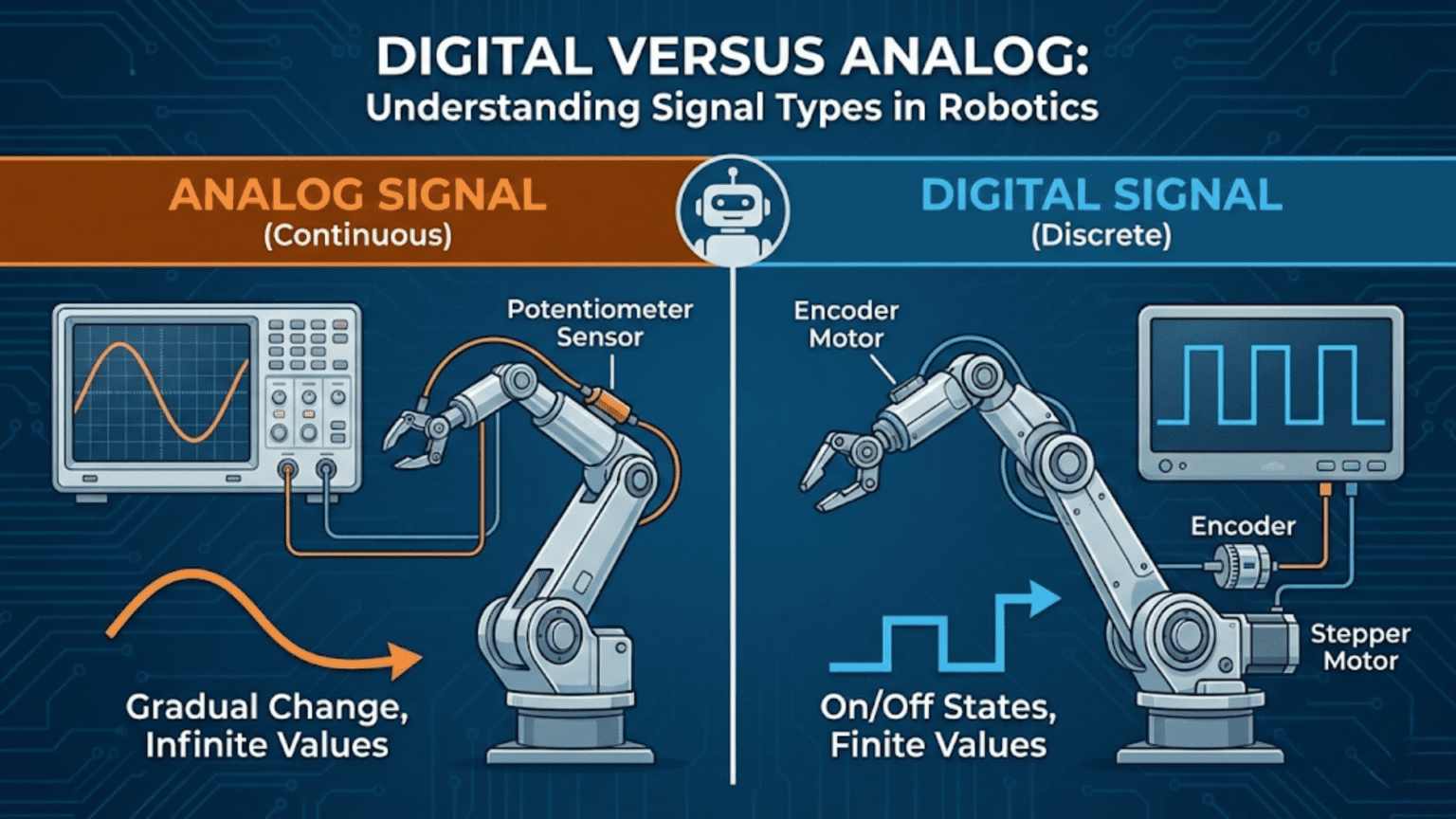
In robotics, analog signals are continuously varying electrical voltages that can take any value within a range—like a dimmer switch that can be set anywhere from off to fully bright—while digital signals exist in only two discrete states: high voltage (representing binary 1) or low voltage (representing binary 0), like a light switch that is either fully on or fully off. Understanding the difference between these two fundamental signal types, knowing when each is appropriate, and knowing how to read, generate, and convert between them is a foundational skill that underlies every sensor interface, motor control method, and communication protocol in robotics.
Introduction
Imagine trying to describe how warm a room is using only the words “hot” and “cold.” You could say “hot” or “cold,” but you couldn’t say “a little warm” or “very slightly above comfortable.” Now imagine having a thermometer that gives you the exact temperature in degrees—25.4°C, 31.7°C, or any value in between. The first approach is digital: limited to two states, simple but coarse. The second is analog: infinitely precise within a range, rich but requiring more processing.
This is the core difference between digital and analog signals, and it runs through every aspect of robotics electronics. The sensors on your robot—do they output a voltage that varies continuously, or do they snap between two levels? The motors you’re controlling—are you switching them fully on and off, or varying their speed smoothly? The communication between your microcontroller and a sensor module—is it sending exact voltage levels, or a series of high/low pulses encoding binary data?
Every wire in your robot carries one of these signal types, and knowing which kind you’re dealing with determines how you read it, how you generate it, how you protect against errors, and how you process the data it carries. Confusing one for the other is a reliable path to hardware damage, frustrating bugs, and sensors that appear broken when they’re actually working perfectly in the wrong context.
This article builds a complete, practical understanding of both signal types—what they are physically, how microcontrollers work with each, when one is better than the other, and how they interact through the conversion processes that sit at the boundary between them.
Analog Signals: The Continuous World
The physical world is fundamentally analog. Temperature doesn’t jump between “cold” and “hot”—it varies continuously through every value in between. Light intensity doesn’t switch between “dark” and “bright”—it spans an unbroken range from absolute darkness to the intensity of the sun. Sound pressure, mechanical force, humidity, chemical concentration, velocity—all of these physical quantities exist as continuous variables that can take any value within their possible range.
Analog signals in electronics mirror this continuous physical reality. An analog electrical signal is a voltage (or sometimes a current) that can take any value within a defined range, typically 0V to 5V or 0V to 3.3V in robotics systems. As the physical quantity being measured changes—the temperature rises, the object gets closer, the motor spins faster—the analog voltage changes proportionally and continuously.
What Analog Signals Look Like
If you connect an oscilloscope to an analog signal and watch it over time, you see a smooth, continuously varying curve. The voltage traces the shape of the physical phenomenon it represents. A temperature sensor as the environment slowly warms produces a slowly rising voltage curve. An accelerometer attached to a vibrating surface produces a sinusoidal voltage that oscillates at the vibration frequency. A potentiometer being slowly turned produces a voltage that rises smoothly from near zero to near the supply voltage.
The mathematical description of an analog signal allows it to take any real number value within its range. Between 2.500V and 2.501V, the signal can pass through 2.5001V, 2.50005V, 2.500001V, and infinitely many other values. This continuity is the defining property of analog signals—there are no gaps, no steps, no discrete jumps.
Common Analog Signal Sources in Robotics
Analog signals appear throughout robotics systems:
Analog sensors produce voltage outputs that represent physical measurements. Potentiometers, thermistors, photoresistors, analog accelerometers, current sensors, pressure sensors, Hall effect position sensors, and microphones all produce analog voltage outputs that vary with the quantity being measured.
Variable voltage sources including batteries produce analog voltages that can be monitored to track state of charge. Battery voltage isn’t a fixed number—it’s an analog voltage that decreases continuously as the battery discharges.
Audio signals produced by microphones and consumed by speakers are classic analog signals. If your robot has voice recognition or audio output capabilities, analog audio signal processing comes into play.
Analog actuator control signals include the voltage level sent to some motor controllers and the wiper input of some audio amplifiers. Driving a voltage-controlled amplifier or a variable-speed fan with a directly applied voltage rather than a digital control interface involves analog signals.
Reading Analog Signals with a Microcontroller
As explained in the previous article, microcontrollers read analog signals using their built-in Analog-to-Digital Converters (ADCs). The analogRead() function on Arduino returns a value from 0 to 1023 representing the input voltage from 0V to 5V (on a 5V system):
// Basic analog signal reading
void loop() {
  int rawValue = analogRead(A0);          // Returns 0–1023
  float voltage = (rawValue / 1023.0) * 5.0;  // Convert to volts

  Serial.print("Raw: "); Serial.print(rawValue);
  Serial.print("  Voltage: "); Serial.print(voltage, 3);
  Serial.println(" V");

  delay(100);
}The key characteristics of analog input on a microcontroller:
- Dedicated pins: Only certain pins (labeled A0, A1, etc.) can read analog signals
- Finite resolution: The 10-bit ADC maps the full voltage range to 1024 discrete steps
- Sampling rate: The ADC takes time to convert (about 100 µs on Arduino Uno)
- Input impedance: The ADC input has a finite impedance; sensors must be able to drive it
Generating Analog Signals from a Microcontroller
True analog output—generating a smoothly varying voltage from a microcontroller—requires either a Digital-to-Analog Converter (DAC) or PWM. Basic Arduino boards like the Uno don’t have a DAC, but more capable microcontrollers like the Arduino Due, ESP32, and Raspberry Pi Pico have one or more DAC channels:
// Arduino Due: true analog output via DAC
void setup() {
  analogWriteResolution(12);  // Set 12-bit resolution (0–4095)
}

void loop() {
  // Sine wave output on DAC pin (DAC0)
  for (int i = 0; i < 360; i++) {
    float sinValue = sin(i * PI / 180.0);
    int dacValue = (int)((sinValue + 1.0) / 2.0 * 4095);  // Map -1..1 to 0..4095
    analogWrite(DAC0, dacValue);
    delayMicroseconds(100);
  }
}Digital Signals: The Binary World
Digital signals operate in an entirely different mode. Rather than carrying information through continuously varying voltage, digital signals convey information through the sequence and timing of transitions between two discrete voltage states: HIGH (representing binary 1) and LOW (representing binary 0).
Voltage Thresholds and Logic Levels
The distinction between HIGH and LOW isn’t perfectly sharp in the physical world. Real digital signals have defined threshold regions:
For 5V systems (Arduino Uno, classic TTL logic):
- Voltages above 3.0V are reliably read as HIGH
- Voltages below 1.5V are reliably read as LOW
- Voltages between 1.5V and 3.0V are in the undefined region—the logic gate may read them as either state
For 3.3V systems (Arduino Due, ESP32, Raspberry Pi, most modern sensors):
- Voltages above 2.0V are reliably read as HIGH
- Voltages below 0.8V are reliably read as LOW
This matters because mixing 5V and 3.3V devices without level shifting can damage the lower-voltage device. A 5V signal applied to a 3.3V microcontroller input can exceed the chip’s maximum rated input voltage and cause permanent damage.
Reading Digital Signals
Reading a digital signal with a microcontroller is much simpler than reading analog. The digitalRead() function returns either HIGH (1) or LOW (0):
const int BUTTON_PIN = 7;
const int LIMIT_SWITCH_PIN = 8;
const int IR_OBSTACLE_PIN = 9;  // Digital IR sensor (not analog)

void setup() {
  Serial.begin(9600);
  // INPUT_PULLUP enables internal pull-up resistor
  // Pin reads HIGH normally, LOW when button/switch connects it to GND
  pinMode(BUTTON_PIN, INPUT_PULLUP);
  pinMode(LIMIT_SWITCH_PIN, INPUT_PULLUP);
  pinMode(IR_OBSTACLE_PIN, INPUT);  // This sensor has its own pull-up
}

void loop() {
  bool buttonPressed = (digitalRead(BUTTON_PIN) == LOW);  // Inverted: LOW = pressed
  bool limitHit = (digitalRead(LIMIT_SWITCH_PIN) == LOW);
  bool obstacleDetected = (digitalRead(IR_OBSTACLE_PIN) == LOW);

  if (buttonPressed)     Serial.println("Button pressed");
  if (limitHit)          Serial.println("Limit switch triggered!");
  if (obstacleDetected)  Serial.println("Obstacle detected");

  delay(50);
}Writing Digital Signals
Generating digital output is equally direct. digitalWrite() sets a pin to either HIGH or LOW:
const int LED_PIN = 13;
const int RELAY_PIN = 6;
const int DIRECTION_PIN = 4;

void setup() {
  pinMode(LED_PIN, OUTPUT);
  pinMode(RELAY_PIN, OUTPUT);
  pinMode(DIRECTION_PIN, OUTPUT);
}

void loop() {
  // Simple blink
  digitalWrite(LED_PIN, HIGH);
  delay(500);
  digitalWrite(LED_PIN, LOW);
  delay(500);

  // Control a relay
  digitalWrite(RELAY_PIN, HIGH);  // Relay on
  delay(2000);
  digitalWrite(RELAY_PIN, LOW);   // Relay off
  delay(2000);

  // Set motor direction
  digitalWrite(DIRECTION_PIN, HIGH);  // Forward
}The Pull-Up and Pull-Down Resistor Problem
A critical practical detail with digital inputs: if a pin is set as an input but nothing is connected to it, the pin “floats”—it picks up random electrical noise and reads unpredictably, sometimes HIGH, sometimes LOW, sometimes rapidly switching between the two. This floating input problem causes many beginner bugs.
The solution is a pull-up or pull-down resistor that ties the input to a known default state:
// External pull-up resistor approach:
// Connect a 10k resistor between the input pin and VCC (5V)
// The pin reads HIGH by default; connecting to GND pulls it LOW

// Internal pull-up approach (simpler):
// Arduino has built-in ~20-50k pull-up resistors on most digital pins
pinMode(SENSOR_PIN, INPUT_PULLUP);
// Pin now reads HIGH by default, LOW when connected to GND

// Pull-down (external only, Arduino has no internal pull-downs):
// Connect a 10k resistor between the input pin and GND
// Pin reads LOW by default; connecting to VCC drives it HIGHThe vast majority of digital sensors in robotics use an active-LOW convention with pull-up resistors: the signal line is normally HIGH (pulled up), and the sensor pulls it LOW when triggered. Understanding this convention explains why so many sensor readings seem “inverted” to beginners—the pin reads LOW exactly when the sensor is active.
PWM: Bridging the Gap Between Digital and Analog
One of the most important and widely misunderstood concepts in robotics electronics is Pulse Width Modulation (PWM)—a technique that uses digital signals (HIGH/LOW switching) to approximate analog effects.
What PWM Actually Is
PWM works by switching a digital pin between HIGH and LOW at a fixed frequency, varying the proportion of time spent HIGH versus LOW. This ratio—called the duty cycle—controls the average power delivered to the load:
- 0% duty cycle: Always LOW → 0% power
- 25% duty cycle: HIGH 25% of the time → 25% average power
- 50% duty cycle: HIGH and LOW equal time → 50% average power
- 75% duty cycle: HIGH 75% of the time → 75% average power
- 100% duty cycle: Always HIGH → 100% power
The switching happens so fast (typically 490–1000 Hz on Arduino) that inductive loads like motors can’t follow the rapid switching—they respond only to the average power. The result is motor speed control that appears continuous even though the underlying signal is purely digital.
// PWM motor speed control
const int MOTOR_PWM_PIN = 5;   // Must be PWM-capable pin (3,5,6,9,10,11 on Uno)
const int MOTOR_DIR_PIN = 4;

void setup() {
  pinMode(MOTOR_PWM_PIN, OUTPUT);
  pinMode(MOTOR_DIR_PIN, OUTPUT);
  digitalWrite(MOTOR_DIR_PIN, HIGH);  // Forward direction
}

void loop() {
  // Gradually increase speed
  for (int speed = 0; speed <= 255; speed++) {
    analogWrite(MOTOR_PWM_PIN, speed);  // 0=stop, 255=full speed
    delay(20);
  }

  // Gradually decrease speed
  for (int speed = 255; speed >= 0; speed--) {
    analogWrite(MOTOR_PWM_PIN, speed);
    delay(20);
  }
}PWM Is Digital, Not Analog
This is a common point of confusion: analogWrite() does NOT produce a true analog voltage. If you measure the pin with a voltmeter set to DC, the meter averages the switching and shows an “average voltage” proportional to duty cycle—making it look analog. But if you look at it with an oscilloscope, you see a square wave rapidly switching between 0V and 5V. It is a digital signal being used to create an analog effect.
This distinction matters because:
- PWM cannot drive analog input pins on ADC-equipped devices expecting a true analog voltage
- PWM signals can cause interference and noise in nearby analog circuits
- Some devices require true analog input, not PWM (audio DACs, true voltage references)
- PWM frequency matters—for motor control and LED dimming, lower frequencies are often fine; for audio applications, the PWM frequency must be much higher than the audible range
PWM for Servo Control
Standard hobby servos use a specific form of PWM with fixed frequency (50 Hz) and variable pulse width (1000–2000 microseconds) to encode position commands—not duty cycle. This is technically called Pulse Position Modulation (PPM) or pulse-width encoding, though it’s commonly grouped under the PWM umbrella:
#include <Servo.h>

Servo myServo;

void setup() {
  myServo.attach(9);  // Servo on pin 9
}

void loop() {
  // Sweep from 0° to 180°
  for (int angle = 0; angle <= 180; angle++) {
    myServo.write(angle);
    delay(15);
  }

  // Sweep back from 180° to 0°
  for (int angle = 180; angle >= 0; angle--) {
    myServo.write(angle);
    delay(15);
  }
}The Servo library generates the precise 50 Hz PWM signal with correct pulse widths automatically. Understanding that servos use digital pulse timing (not analog voltage) explains why you can control them from any digital output pin with the right timing, not just analog-capable pins.
Digital Communication Protocols: Structured Digital Signals
Many modern sensors don’t output a simple analog voltage or a single digital HIGH/LOW—they communicate using structured digital protocols where sequences of pulses encode complex data. Understanding these protocols requires understanding how digital signals can carry rich information beyond simple on/off states.
UART (Serial Communication)
UART (Universal Asynchronous Receiver-Transmitter) is the most basic digital communication protocol and the one behind the Arduino’s Serial.println() functions. It encodes data as a series of bits transmitted at a fixed rate (baud rate):
// UART communication - reading a GPS module
// GPS sends data as ASCII text at 9600 baud

#include <SoftwareSerial.h>

SoftwareSerial gpsSerial(10, 11);  // RX, TX

void setup() {
  Serial.begin(9600);       // For debugging output
  gpsSerial.begin(9600);    // For GPS module
}

void loop() {
  while (gpsSerial.available()) {
    char c = gpsSerial.read();
    Serial.print(c);  // Pass GPS NMEA sentences to debug monitor
  }
}UART uses two wires (TX and RX), is point-to-point (one sender, one receiver), and requires both sides to agree on the baud rate beforehand—hence “asynchronous.”
I2C (Inter-Integrated Circuit)
I2C uses just two wires—SDA (data) and SCL (clock)—to connect multiple devices on a shared bus. Each device has a unique address, allowing a single microcontroller to communicate with many sensors without dedicating separate pins to each:
// I2C - Reading an MPU6050 accelerometer/gyroscope
// Multiple I2C devices can share the same SDA/SCL lines

#include <Wire.h>
#include <MPU6050.h>

MPU6050 mpu;

void setup() {
  Serial.begin(9600);
  Wire.begin();          // Initialize I2C bus (SDA=A4, SCL=A5 on Uno)
  mpu.initialize();

  if (mpu.testConnection()) {
    Serial.println("MPU6050 connected successfully");
  } else {
    Serial.println("MPU6050 connection failed");
  }
}

void loop() {
  int16_t ax, ay, az;
  int16_t gx, gy, gz;

  mpu.getMotion6(&ax, &ay, &az, &gx, &gy, &gz);

  Serial.print("Accel: ");
  Serial.print(ax); Serial.print(", ");
  Serial.print(ay); Serial.print(", ");
  Serial.println(az);

  delay(100);
}I2C is ideal for connecting multiple low-speed sensors (IMUs, barometers, displays, EEPROMs) to a single microcontroller with minimal wiring.
SPI (Serial Peripheral Interface)
SPI is faster than I2C and uses four wires: MOSI (master out), MISO (master in), SCK (clock), and SS (slave select). It’s used for high-speed devices like SD cards, high-resolution ADCs, and fast displays:
// SPI - Reading an MCP3208 8-channel 12-bit ADC
// Useful when you need more or higher-resolution analog channels

#include <SPI.h>

const int CS_PIN = 10;  // Chip Select

void setup() {
  Serial.begin(9600);
  SPI.begin();
  pinMode(CS_PIN, OUTPUT);
  digitalWrite(CS_PIN, HIGH);  // Deselect by default
}

int readMCP3208(int channel) {
  // MCP3208 protocol: start bit + single/diff + channel bits
  int commandBits = 0b11000000 | (channel << 3);

  digitalWrite(CS_PIN, LOW);  // Select chip
  SPI.transfer(0x01);          // Start bit
  int highByte = SPI.transfer(commandBits) & 0x0F;
  int lowByte  = SPI.transfer(0x00);
  digitalWrite(CS_PIN, HIGH); // Deselect chip

  return (highByte << 8) | lowByte;  // Combine into 12-bit value
}

void loop() {
  int channel0 = readMCP3208(0);
  float voltage = (channel0 / 4095.0) * 5.0;  // 12-bit ADC, 5V reference

  Serial.print("Channel 0: "); Serial.print(channel0);
  Serial.print(" ("); Serial.print(voltage, 3); Serial.println(" V)");

  delay(100);
}OneWire
The DS18B20 digital temperature sensor uses the OneWire protocol—it sends a complete digital temperature reading (with 0.0625°C resolution) over a single wire. This is a good example of how digital communication can replace an analog signal with richer data:
// OneWire DS18B20 digital temperature sensor
// Provides 12-bit temperature data over a single wire

#include <OneWire.h>
#include <DallasTemperature.h>

OneWire oneWire(2);               // Data pin 2
DallasTemperature sensors(&oneWire);

void setup() {
  Serial.begin(9600);
  sensors.begin();
}

void loop() {
  sensors.requestTemperatures();   // Send conversion command
  float tempC = sensors.getTempCByIndex(0);

  Serial.print("Temperature: ");
  Serial.print(tempC);
  Serial.println(" °C");

  delay(1000);
}Compare this to the analog LM35 from the previous article: both measure temperature, but the DS18B20 outputs digital data with 0.0625°C resolution directly, while the LM35 outputs an analog voltage requiring ADC conversion. The digital approach eliminates ADC noise, calibration error, and wiring sensitivity at the cost of requiring protocol handling.
Head-to-Head: When to Choose Analog vs. Digital
With both signal types understood deeply, the practical question becomes: for a given robotics application, which should you use?
Comparison Table: Analog vs. Digital Signals in Robotics
| Property | Analog Signals | Digital Signals |
|---|---|---|
| Information encoding | Voltage level (continuous) | Bit sequence (discrete) |
| Resolution | Limited by ADC bits (10–16 bits typical) | Effectively unlimited (more bits = more data) |
| Noise immunity | Low — noise directly corrupts the value | High — noise must exceed threshold to flip a bit |
| Reading hardware needed | ADC (Analog-to-Digital Converter) | Digital input pin |
| Wiring complexity | Simple (one wire + ground) | Varies (1–4+ wires depending on protocol) |
| Distance transmission | Degrades with cable length and interference | Can be robust over long distances with proper protocol |
| Data richness | Single value per wire | Unlimited data: multiple channels, metadata, checksums |
| Processing required | Conversion, calibration, filtering | Protocol decoding, often handled by library |
| Real-time latency | Immediate (just read ADC) | Slight delay for protocol communication |
| Cost | Often lower (simple sensor designs) | Slightly higher (sensor needs onboard processing) |
| Best for | Position feedback, joystick input, simple sensors | IMUs, GPS, multi-axis sensors, long-distance sensing |
Choosing Analog: Situations Where It Wins
Lowest latency is required. An analog sensor read with analogRead() takes about 100 µs. A digital protocol exchange might take several milliseconds. For a fast control loop that needs to sample at 10 kHz or more, analog is often the only viable option.
The simplest possible wiring is needed. A potentiometer connected to an analog input pin with two wires and a power connection is about as simple as electronics gets. For throwaway projects, prototypes, and situations where simplicity is paramount, analog wins.
Measuring a single, simple physical quantity. If you need exactly one measurement—temperature, position, light level—a simple analog sensor with a voltage output is often cleaner than a digital sensor requiring protocol initialization and library management.
You need precise control over sampling timing. With analog, you decide exactly when to sample by calling analogRead(). With digital protocols, the communication has its own timing requirements that may not align perfectly with your control loop.
Choosing Digital: Situations Where It Wins
Long cable runs. Analog signals degrade with cable length—resistance drops voltage, capacitance rolls off high frequencies, and inductance couples noise. A 5-meter cable carrying an analog sensor signal may introduce significant errors. A digital signal with appropriate logic levels can traverse the same cable with much greater integrity, because small noise perturbations don’t change the logical value of the signal as long as they don’t push the voltage past the switching threshold.
Multiple measurements from one sensor. An IMU sensor (accelerometer + gyroscope + sometimes magnetometer) measures 6 or 9 axes of data. Providing this as analog would require 6 or 9 separate analog wires and ADC channels. Over I2C, all this data arrives over just two wires.
High precision requirements. A 16-bit I2C ADC chip provides 65,536 levels versus the Arduino’s built-in 1,024 levels. For precision weighing, precision temperature measurement, or precision position sensing, a digital sensor with high-resolution internal ADC often outperforms reading a simple analog sensor.
Sensors in noisy environments. Near motors, switching power supplies, and RF transmitters, analog signals pick up interference that directly corrupts readings. Digital signals, with their wide noise margins, are far more immune. This is why industrial sensors in factories with large motors use digital field buses, not analog 0–5V signals (though the classic 4–20 mA current loop remains common in industrial analog sensing specifically because current signals reject noise better than voltage signals).
When you need data integrity verification. Many digital protocols include checksums or CRC (Cyclic Redundancy Check) codes that detect transmission errors. If a bit flip occurs due to noise, the protocol can detect and reject the corrupted reading. Analog has no equivalent mechanism—noise corruption is silent and undetectable.
Level Shifting: Connecting 5V and 3.3V Devices Safely
A critical practical skill in modern robotics is safely connecting devices that operate at different logic voltages—particularly mixing 5V Arduino Unos with 3.3V sensors, ESP8266/ESP32 modules, and Raspberry Pi GPIO.
The Voltage Mismatch Problem
Most modern sensors and communication modules operate at 3.3V logic. Many classic Arduino boards operate at 5V. Connecting them directly:
- 5V output → 3.3V input: The 3.3V device’s input sees 5V—typically 1.7V above its absolute maximum. This can cause immediate damage or gradual degradation.
- 3.3V output → 5V input: The 5V device may not reliably read the 3.3V HIGH as a logic HIGH (threshold is typically 3.0V, so it often works, but is not guaranteed).
Resistor Voltage Divider (One-Way, Output Only)
For connections where data only flows in one direction (microcontroller output → sensor input), a simple resistor divider safely scales 5V down to 3.3V:
5V pin ──[R1: 1kΩ]──┬── To 3.3V device input
                    │
                  [R2: 2kΩ]
                    │
                   GND

Output voltage = 5V × (2kΩ / (1kΩ + 2kΩ)) = 3.33V ✓// No code needed for a resistor divider - it's purely hardware
// The microcontroller simply uses digitalWrite() normally
// The hardware divider reduces the voltage before reaching the 3.3V deviceBidirectional Level Shifter Module
For I2C and other bidirectional protocols, a dedicated level shifter module is needed. The most common uses a BSS138 MOSFET and works for both directions:
// With a proper level shifter, the code is identical
// The hardware module handles the voltage translation transparently

// Same I2C code works whether using a level shifter or not:
Wire.begin();
Wire.beginTransmission(0x68);  // MPU6050 address
Wire.write(0x6B);               // Power management register
Wire.write(0);                  // Wake up
Wire.endTransmission();The level shifter is transparent to the software—it doesn’t change what you write, only what voltages the hardware sees.
Interrupts: Reacting to Digital Signal Changes Instantly
One powerful advantage of digital signals is the ability to use hardware interrupts—a mechanism that causes the microcontroller to immediately stop what it’s doing and execute a special function the moment a pin changes state.
This is particularly important for:
- Encoder reading: Every encoder pulse must be counted immediately or rotation information is lost
- Limit switch detection: The robot must stop the moment a limit switch triggers, regardless of what the main loop is doing
- Button debouncing and response: Detecting a button press without polling
// Hardware interrupt for encoder counting
// digitalRead() polling would miss pulses at high speed

volatile long encoderCount = 0;  // volatile: modified in interrupt

void encoderISR() {
  encoderCount++;  // Increment on every rising edge of encoder signal
}

// For limit switch - emergency stop
volatile bool emergencyStop = false;

void limitSwitchISR() {
  emergencyStop = true;  // Set flag immediately when limit hit
}

void setup() {
  Serial.begin(9600);

  // Attach interrupt to pin 2 (INT0) - triggers on RISING edge
  attachInterrupt(digitalPinToInterrupt(2), encoderISR, RISING);

  // Attach interrupt to pin 3 (INT1) - triggers on FALLING edge (active-LOW switch)
  attachInterrupt(digitalPinToInterrupt(3), limitSwitchISR, FALLING);
}

void loop() {
  if (emergencyStop) {
    stopAllMotors();
    Serial.println("EMERGENCY STOP - limit switch triggered");
    while (true);  // Halt
  }

  Serial.print("Encoder count: ");
  Serial.println(encoderCount);
  delay(100);
}Interrupts are a purely digital concept—they work by detecting voltage level transitions on digital input pins. The speed and determinism they provide are impossible to replicate with analog signal processing.
Real-World Robotics Scenarios: Applying the Right Signal Type
Understanding theory is one thing; applying it correctly in real robot designs is another. Here are practical scenarios where choosing correctly between analog and digital signals makes a meaningful difference.
Scenario 1: Robot Arm with Multiple Joints
Angle sensing approach A (analog): Potentiometer at each joint connected to Arduino analog pins. Simple, cheap, immediate readings. Works well for 2–3 joints on an Arduino Uno (which has 6 analog inputs). Problem: limited to 6 joints without an external multiplexer, moderate precision (10-bit ADC), and susceptible to motor noise.
Angle sensing approach B (digital): Magnetic encoder with I2C output (like the AS5600) at each joint. Higher precision (12-bit), better noise immunity, all joints share one I2C bus. Problem: requires I2C addressing scheme if multiple identical sensors used, slightly more complex library usage.
Best practice: For 1–3 joints on a prototype, analog potentiometers are fast and simple. For 4+ joints, precision requirements above 0.5°, or noise-sensitive environments, digital magnetic encoders are superior.
Scenario 2: Obstacle Detection Array
Analog approach: Multiple Sharp IR sensors, each connected to its own analog input pin. Direct distance readings after conversion. Problem: each sensor needs its own ADC channel; with a 5-sensor array you’ve used most of the Uno’s analog inputs.
Digital approach: Ultrasonic sensors (HC-SR04) using digital trigger/echo pins, or I2C ToF (Time-of-Flight) sensors like the VL53L0X. Each sensor provides high-precision distance readings; multiple I2C ToF sensors share the bus (with address configuration).
Best practice: For simple proximity detection (is something closer than X cm?), digital threshold-output IR sensors (dirt cheap, one digital pin each) work great. For precise distance values across many sensors, I2C ToF sensors provide the best combination of precision, noise immunity, and wire efficiency.
Scenario 3: Joystick for Teleoperation
Analog approach: Dual-axis thumbstick (two potentiometers) connected to two analog pins. Direct, immediate mapping of stick position to motor speed. Natural for proportional control.
Digital approach: Encode joystick position to digital values and transmit via serial or I2C. Adds latency and complexity without benefit for local control.
Best practice: Analog, clearly. Joystick inputs are quintessentially analog—you want proportional control with immediate response. This is one of the clearest cases where analog is the right tool.
Scenario 4: Robot-to-Robot Communication
Analog approach: Transmit control signals as analog voltages. Fails completely over any meaningful distance due to voltage drops and noise pickup on long cables.
Digital approach: Use UART, I2C, CAN bus, or wireless digital protocols (Bluetooth, WiFi, LoRa). Data can be verified with checksums, transmitted over long distances, and shared between multiple devices.
Best practice: Digital, always. Any data that needs to travel more than a few centimeters, be stored, or be shared between devices should be digital. The noise immunity, error detection capability, and data richness of digital communication have no analog equivalent.
The ADC and DAC: The Bridges Between Worlds
No robotics system is purely analog or purely digital—they exist in the physical world (analog) but are controlled by digital microcontrollers. The ADC and DAC are the bridges that allow these two worlds to communicate.
ADC Summary (Analog → Digital)
The ADC converts an analog voltage to a digital number. It determines how precisely the digital system can represent the analog world. Key parameters:
- Resolution: Number of bits (8, 10, 12, 16, 24) → 256, 1024, 4096, 65536, or 16 million levels
- Sample rate: How many conversions per second (kHz to MHz for fast ADCs)
- Reference voltage: The voltage corresponding to maximum digital output
- Input range: The voltage range the ADC can handle without damage
DAC Summary (Digital → Analog)
The DAC converts a digital number to an analog voltage. It determines how precisely the digital system can control an analog output. Most Arduino boards lack a built-in DAC, but external DAC chips (like the MCP4725 over I2C) are inexpensive and easy to use:
// MCP4725 12-bit DAC over I2C
// Generates true analog output voltages from digital values

#include <Wire.h>

const int MCP4725_ADDR = 0x60;

void setDACOutput(uint16_t value) {
  // value: 0 (0V) to 4095 (Vcc)
  Wire.beginTransmission(MCP4725_ADDR);
  Wire.write(0x40);                    // Write DAC register command
  Wire.write((value >> 4) & 0xFF);     // Upper 8 bits
  Wire.write((value & 0x0F) << 4);     // Lower 4 bits
  Wire.endTransmission();
}

void setup() {
  Wire.begin();
  setDACOutput(0);  // Start at 0V
}

void loop() {
  // Generate a ramp output: 0V to Vcc and back
  for (int i = 0; i <= 4095; i += 10) {
    setDACOutput(i);
    delay(2);
  }
  for (int i = 4095; i >= 0; i -= 10) {
    setDACOutput(i);
    delay(2);
  }
}True DAC output is useful when driving voltage-controlled devices, generating reference voltages for sensor circuits, audio output, or any application requiring a genuine continuous analog voltage rather than a PWM approximation.
Practical Debugging: Identifying Signal Type Problems
Many robotics wiring and coding problems stem from signal type mismatches. Here’s a quick guide to diagnosing common issues:
Symptom: Digital sensor always reads HIGH (or always LOW)
- Check if the sensor is active-LOW (most are) — LOW means active, not broken
- Check for missing pull-up resistor on a floating input
- Verify the sensor’s supply voltage matches its rated operating voltage
- Check for reversed VCC/GND connections
Symptom: Analog reading is always 0 or always 1023
- 0: Sensor output is not connected (floating low) or sensor not powered
- 1023: Sensor output voltage exceeds reference voltage (overvoltage condition)
- Check sensor supply voltage and verify output is within 0–Vref range
Symptom: Analog reading is noisy and unstable
- Add filtering (EMA or moving average) in software
- Add a 100nF ceramic capacitor between sensor VCC and GND
- Separate analog sensor ground from motor driver ground
- Use analogReference(INTERNAL) for a more stable reference
Symptom: I2C device not found
- Run an I2C scanner to find what addresses are on the bus
- Check SDA/SCL connections (A4/A5 on Uno, different on other boards)
- Verify 3.3V vs 5V logic compatibility — may need level shifter
- Check for missing pull-up resistors on SDA and SCL (usually 4.7kΩ to VCC)
// I2C scanner - finds all connected I2C device addresses
#include <Wire.h>

void setup() {
  Wire.begin();
  Serial.begin(9600);
  Serial.println("Scanning I2C bus...");

  for (byte address = 1; address < 127; address++) {
    Wire.beginTransmission(address);
    byte error = Wire.endTransmission();

    if (error == 0) {
      Serial.print("Device found at address 0x");
      if (address < 16) Serial.print("0");
      Serial.println(address, HEX);
    }
  }
  Serial.println("Scan complete.");
}

void loop() {}Summary
Analog and digital signals are two fundamentally different ways of encoding and transmitting information in electronic systems. Analog signals carry information as a continuously varying voltage—rich, immediate, but sensitive to noise and limited by ADC precision. Digital signals carry information as sequences of HIGH/LOW states—discrete, noise-resistant, capable of encoding unlimited data, but requiring protocol handling.
Neither is universally better. Analog signals excel at capturing continuous physical quantities directly, providing the lowest latency feedback, and simplifying circuits where a single voltage level is all that’s needed. Digital signals excel at long-distance transmission, multi-parameter sensing, noise immunity, and rich data communication between devices.
Most real robotics systems use both extensively. The sensors close to the physics—potentiometers, temperature sensors, force sensors, current sensors—are often analog. The sensors with onboard intelligence—IMUs, GPS modules, encoders—are digital. Motors are driven through PWM (digital signals creating analog effects). Communication between subsystems is digital. Control loops bridge the two worlds with ADCs and DACs.
Understanding both signal types completely—their physical nature, how microcontrollers read and generate each, when one is better than the other, and how they interact at conversion boundaries—gives you the complete toolkit for designing, building, and debugging any robotic electronics system you’ll encounter.
The next article moves from signals to structures: a deep dive into the materials used to build robot bodies—plastic, wood, aluminum, and 3D-printed parts—and how to choose the right material for the mechanical demands of your specific robot design.