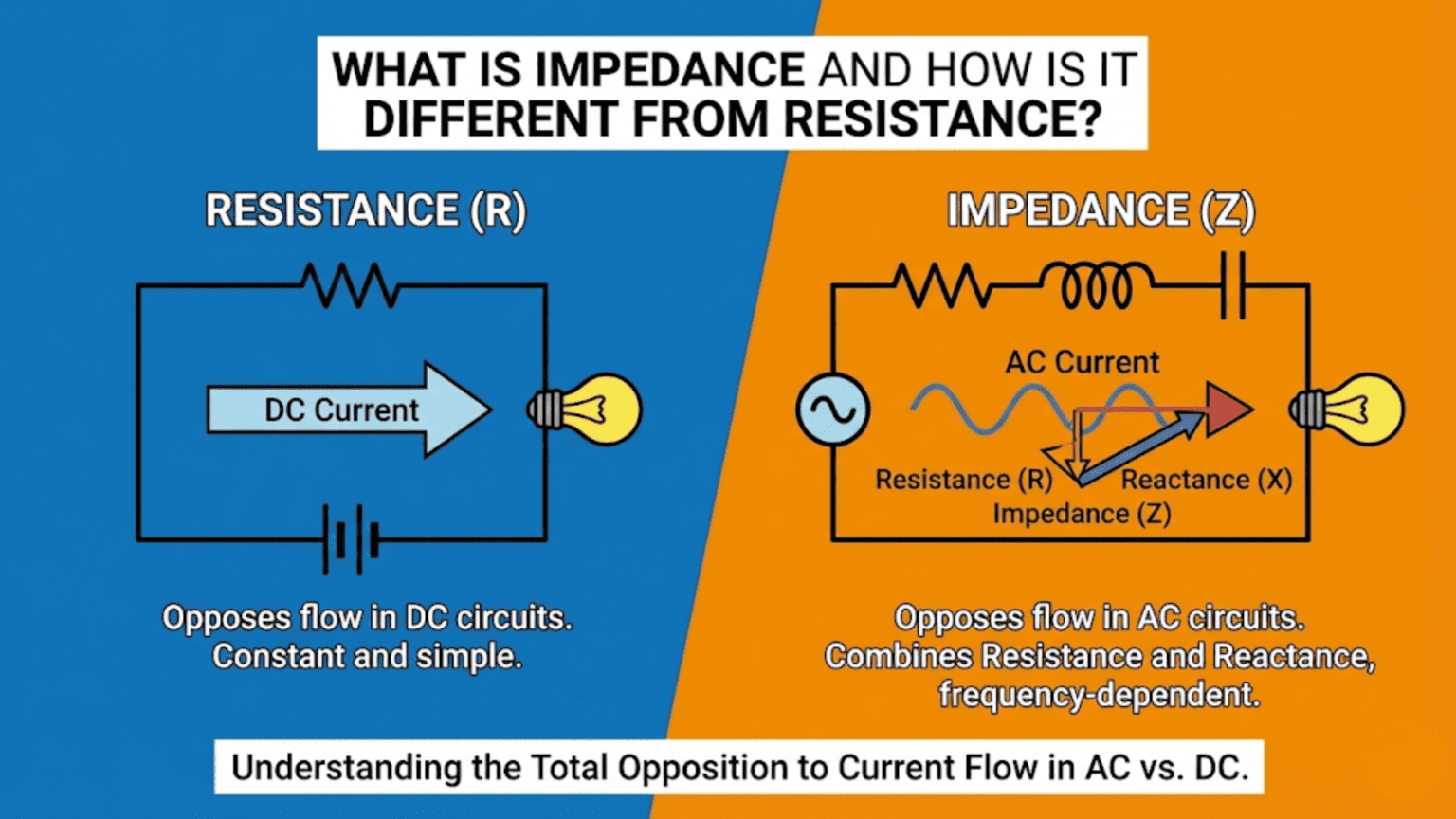
Resistance is a component’s opposition to current flow that is constant regardless of frequency—it converts electrical energy into heat and obeys Ohm’s Law (V = IR) at all frequencies. Impedance is the total opposition to current flow in an AC circuit, combining resistance with reactance—the frequency-dependent opposition created by capacitors and inductors. While resistance is a single number (ohms), impedance is a complex quantity with both magnitude (how much it opposes current) and phase angle (whether current leads or lags voltage). At DC and very low frequencies, impedance approaches resistance; at higher frequencies, the reactive components of capacitors and inductors become significant and impedance changes with frequency.
Introduction: Beyond Ohm’s Law
Every beginner in electronics learns Ohm’s Law early: V = IR. Voltage equals current times resistance. Simple, powerful, universally applicable. A 100Ω resistor with 5V across it always draws exactly 50mA. The relationship is constant, predictable, and independent of everything except those three variables.
Then you encounter capacitors and inductors, and Ohm’s Law starts to feel incomplete. Connect a capacitor to a DC source and no steady-state current flows at all — the capacitor charges and stops. Connect that same capacitor to an AC source and current does flow, but the amount depends on the frequency: double the frequency and double the current for the same voltage. Connect an inductor to DC and it behaves like a short circuit after initial transients. Connect it to AC and it strongly resists high-frequency current while passing low-frequency current easily.
These behaviors are perfectly orderly — they follow precise mathematical rules — but they’re not captured by simple resistance. To describe the complete opposition to current that a real circuit presents to AC signals, we need a more complete concept: impedance.
Impedance is one of those concepts that, once truly understood, transforms how you think about electronics. It explains why audio cables have specifications, why antenna matching matters, why speakers have both a DC resistance and a much more complex AC behavior, why a capacitor blocks DC but passes AC, why filters work, why decoupling capacitors have frequency ranges, and why transmission lines must be terminated. These aren’t separate unexplained phenomena — they’re all manifestations of the same underlying concept.
This article builds a complete understanding of impedance from the ground up. We’ll start with the familiar ground of resistance, show why it’s insufficient for AC circuits, introduce reactance as the frequency-dependent opposition of capacitors and inductors, combine resistance and reactance into the full complex impedance concept, and then see how impedance understanding applies across practical electronics.
The mathematics involved uses vectors and complex numbers, but we’ll develop every concept geometrically and intuitively before introducing formulas — so even if complex numbers feel unfamiliar, the physics will be clear.
Part 1: Resistance Revisited
What Resistance Really Is
Resistance is the property of a material that converts electrical energy into heat when current flows through it. In a resistor, electrons collide with atoms in the material, transferring kinetic energy as thermal energy. This energy conversion is irreversible — once converted to heat, it cannot be recovered as electrical energy.
Key properties of resistance:
- Frequency-independent: A 100Ω resistor is 100Ω at DC, at 1kHz, at 1MHz, at 1GHz (up to parasitic effects)
- In phase: Voltage and current through a resistor are always in phase — they peak and cross zero at the same time
- Energy dissipation: Power is dissipated as heat: P = I²R = V²/R
Ohm’s Law for resistors: V = I × R (valid at all frequencies, DC and AC alike) I = V / R R = V / I
For a purely resistive circuit, voltage and current waveforms look identical — same phase, same frequency, only different amplitude.
The Phasor Concept: Representing AC Signals
Before introducing reactance, we need a way to represent AC signals that captures both their amplitude and their timing relationship to each other.
A phasor is a rotating vector that represents a sinusoidal signal. The length of the vector represents the amplitude; its angle represents the phase relationship to a reference.
For purely resistive circuits, all phasors point in the same direction — voltage and current are perfectly aligned (in phase). For reactive circuits, current and voltage phasors point in different directions — they have a phase difference.
This phase relationship is at the heart of impedance.
Part 2: Reactance — The Frequency-Dependent Opposition
Capacitive Reactance: Capacitors in AC Circuits
A capacitor opposes changes in voltage. Its current-voltage relationship is: I = C × dV/dt
For a sinusoidal voltage V = V_peak × sin(ωt): I = C × d/dt[V_peak × sin(ωt)] = C × ω × V_peak × cos(ωt)
The current is proportional to ω (angular frequency) — more current flows at higher frequencies.
Capacitive reactance (X_C): The magnitude of a capacitor’s opposition to AC current: X_C = 1 / (2π × f × C) = 1 / (ωC)
Units: Ohms (Ω) — same as resistance
Frequency dependence:
- At DC (f = 0): X_C = ∞ (capacitor blocks DC completely)
- At low frequency: X_C is large (capacitor strongly opposes current)
- At high frequency: X_C is small (capacitor barely opposes current)
- As f → ∞: X_C → 0 (capacitor becomes a short circuit)
Example calculations for a 100nF capacitor:
- At 100Hz: X_C = 1/(2π × 100 × 100×10⁻⁹) = 15,915Ω ≈ 16kΩ
- At 1kHz: X_C = 1,592Ω ≈ 1.6kΩ
- At 10kHz: X_C = 159Ω
- At 100kHz: X_C = 15.9Ω
- At 1MHz: X_C = 1.59Ω
The phase relationship: For a capacitor, current leads voltage by 90°. When voltage is zero and about to increase, maximum current is already flowing to charge the capacitor. When voltage reaches its peak, current is zero (capacitor fully charged, not charging). The current waveform is 90° ahead of the voltage waveform.
Memory aid: “ICE” — for a capacitor (C), current (I) leads voltage (E for EMF): I leads E in Capacitor → ICE
Inductive Reactance: Inductors in AC Circuits
An inductor opposes changes in current. Its voltage-current relationship is: V = L × dI/dt
For a sinusoidal current I = I_peak × sin(ωt): V = L × d/dt[I_peak × sin(ωt)] = L × ω × I_peak × cos(ωt)
The voltage is proportional to ω — more voltage is needed to force the same current at higher frequencies.
Inductive reactance (X_L): The magnitude of an inductor’s opposition to AC current: X_L = 2π × f × L = ωL
Units: Ohms (Ω)
Frequency dependence:
- At DC (f = 0): X_L = 0 (inductor is a short circuit at DC — just a wire)
- At low frequency: X_L is small (inductor barely opposes slow current changes)
- At high frequency: X_L is large (inductor strongly opposes rapid current changes)
- As f → ∞: X_L → ∞ (inductor blocks high-frequency signals)
Example calculations for a 10μH inductor:
- At 100Hz: X_L = 2π × 100 × 10×10⁻⁶ = 0.00628Ω (essentially short circuit)
- At 1kHz: X_L = 0.0628Ω
- At 10kHz: X_L = 0.628Ω
- At 100kHz: X_L = 6.28Ω
- At 1MHz: X_L = 62.8Ω
- At 10MHz: X_L = 628Ω
The phase relationship: For an inductor, voltage leads current by 90°. To build up current in an inductor, voltage must be applied first; the current builds up gradually afterward.
Memory aid: “ELI” — for an inductor (L), voltage (E) leads current (I): E leads I in Linductor → ELI
Combined: “ELI the ICE man” — E leads I in L (inductor); I leads E in C (capacitor)
Reactance vs. Resistance: The Key Differences
| Property | Resistance (R) | Reactance (X) |
|---|---|---|
| Source | Energy dissipation (collisions) | Energy storage (electric/magnetic field) |
| Frequency dependence | None (constant) | Strong (X_C decreases with f, X_L increases with f) |
| Phase relationship | V and I in phase | V and I 90° out of phase |
| Energy fate | Dissipated as heat (permanent) | Stored and returned (no net loss per cycle) |
| DC behavior | R = constant | X_C = ∞ (blocks DC), X_L = 0 (passes DC) |
| Units | Ohms (Ω) | Ohms (Ω) |
The critical distinction on energy: A reactance stores energy during one quarter-cycle and returns it during the next. No net energy is dissipated per complete cycle (in ideal components). This is why capacitors and inductors are called reactive components — they react to, but don’t permanently absorb, AC energy. Resistance absorbs energy permanently — it cannot be recovered.
Part 3: Impedance — Combining Resistance and Reactance
The Impedance Triangle
When a circuit contains both resistance and reactance, the total opposition to current is their combination — but not a simple sum. Because resistance is in-phase with current while reactance is 90° out of phase, they add as vectors (phasors) rather than as simple numbers.
The impedance triangle: For a circuit with resistance R and reactance X:
         (hypotenuse = impedance magnitude)
       /|
  |Z| / |
     /  | X
    /   |
   /θ   |
  ──────┘
    R
(adjacent) (opposite)Impedance magnitude: |Z| = √(R² + X²)
Phase angle: θ = arctan(X / R)
Positive θ: Inductive (voltage leads current) Negative θ: Capacitive (current leads voltage)
Complex Impedance Notation
The most mathematically complete representation uses complex numbers:
Z = R + jX
Where:
- R is the real part (resistance — in phase with current)
- X is the imaginary part (reactance — 90° out of phase)
- j = √(-1) (the imaginary unit, called i in pure mathematics but j in electronics to avoid confusion with current symbol i)
For capacitors: Z_C = 1/(jωC) = -j/(ωC) = -jX_C (Negative imaginary part — current leads voltage)
For inductors: Z_L = jωL = jX_L (Positive imaginary part — voltage leads current)
For resistors: Z_R = R (Real — in phase)
Series impedances add: Z_total = Z_1 + Z_2 + Z_3 + … Z_RC_series = R + 1/(jωC) = R – j/(ωC) |Z_RC_series| = √(R² + 1/(ωC)²)
Parallel impedances combine as: 1/Z_total = 1/Z_1 + 1/Z_2 + …
Practical Impedance Calculations
Example 1: Series RC circuit at audio frequency R = 10kΩ, C = 10nF, frequency = 1kHz
X_C = 1/(2π × 1000 × 10×10⁻⁹) = 15,915Ω
Z = √(10,000² + 15,915²) = √(10⁸ + 2.53×10⁸) = √(3.53×10⁸) = 18,796Ω ≈ 18.8kΩ
Phase angle: θ = arctan(-15,915/10,000) = arctan(-1.59) ≈ -58° (capacitive, current leads)
Example 2: Series RL circuit at radio frequency R = 50Ω, L = 1μH, frequency = 10MHz
X_L = 2π × 10×10⁶ × 1×10⁻⁶ = 62.8Ω
Z = √(50² + 62.8²) = √(2500 + 3944) = √6444 = 80.3Ω
Phase angle: θ = arctan(62.8/50) = arctan(1.256) ≈ +51° (inductive, voltage leads)
Example 3: Parallel LC circuit (resonance) L = 10μH, C = 100pF, frequency = 5.03MHz (resonant frequency)
At resonance: X_L = X_C f_resonance = 1/(2π√(LC)) = 1/(2π√(10×10⁻⁶ × 100×10⁻¹²)) = 5.03MHz
At resonance, ideal parallel LC presents infinite impedance (open circuit to AC at that frequency) — current circulates in the LC tank but nothing flows in or out. Real circuits have resistance in the inductor that limits this to a very high but finite impedance.
Part 4: Resonance — When Reactances Cancel
Series Resonance
In a series RLC circuit, impedance is: Z = R + j(X_L – X_C) = R + j(ωL – 1/ωC)
At the resonant frequency, X_L = X_C, so the imaginary part cancels: Z = R (purely resistive at resonance)
Resonant frequency: f₀ = 1 / (2π√(LC))
At series resonance:
- Impedance is minimum (= R only)
- Current is maximum
- Voltage across L and C can be much larger than supply voltage (by factor Q)
- The circuit is purely resistive (unity power factor)
Q factor (Quality factor): Q = X_L / R = ωL / R (at resonance)
Higher Q = sharper resonance peak = more selective filter
Applications of series resonance:
- Band-pass filters
- Crystal oscillators (crystal is equivalent to very high-Q series resonant circuit)
- RF tank circuits in transmitters
Parallel Resonance
In a parallel LC circuit: At resonance, ideal parallel LC presents infinite impedance. In practice, the coil resistance R limits this to: Z_max ≈ L / (C × R) = Q × ωL
At parallel resonance:
- Impedance is maximum
- Current from source is minimum
- High circulating current within the LC tank
- Purely resistive at resonance frequency
Applications of parallel resonance:
- Band-stop (notch) filters
- RF amplifier loads (tuned amplifiers)
- Impedance transformation
- Tank circuits in oscillators
Part 5: Why Impedance Matters Everywhere
Impedance Matching: Maximum Power Transfer
When a source with source impedance Z_s drives a load with impedance Z_L, maximum power transfers when Z_L = Z_s* (complex conjugate matching).
For purely resistive systems: maximum power when R_L = R_s. For complex impedances: maximum power when R_L = R_s AND X_L = -X_s (reactive parts cancel).
Why this matters:
- Audio systems: Loudspeaker impedance (nominally 4Ω or 8Ω) must be matched to power amplifier output impedance for maximum power transfer
- RF systems: Antenna impedance (typically 50Ω or 75Ω) must match transmission line and transmitter/receiver impedance to minimize reflections
- Interconnects: Source and load impedances determine signal integrity on long cables
Impedance mismatch consequences:
- Reduced power transfer (part of power reflected back to source)
- Standing waves on transmission lines at RF frequencies
- Reflections causing signal quality degradation at high frequencies
- In extreme cases: reflections damage the source (RF power amplifiers particularly vulnerable)
Filter Design: Impedance as a Tool
Filters work because reactances change with frequency. A low-pass RC filter:
Input ──[R]──┬── Output
             │
            [C]
             │
GNDAt low frequency: X_C >> R, most voltage appears at output (capacitor barely conducts) At high frequency: X_C << R, most voltage drops across R, little at output (capacitor short-circuits output)
Cutoff frequency (where X_C = R): f_c = 1 / (2π × R × C)
At f_c, output is -3dB (70.7% of input voltage).
The entire theory of filter design — low-pass, high-pass, band-pass, band-stop, Butterworth, Chebyshev, Bessel — is an elaboration of impedance relationships between components at different frequencies.
Audio: Loudspeaker Impedance
A loudspeaker’s impedance is not a single resistor value. It has:
- DC resistance (Re): The voice coil wire resistance (~3–6Ω for nominal 8Ω speaker)
- Voice coil inductance (Le): Causes impedance to rise at high frequencies
- Mechanical resonance (fs): Large impedance peak at the speaker’s natural resonant frequency (typically 40–100Hz for woofers)
- Complex variation across audio band: Speaker nominal “8Ω” may vary from 6Ω to 30Ω across 20Hz–20kHz
This complex impedance behavior is why:
- Speaker crossover networks use frequency-dependent L and C components
- Amplifiers must drive varying impedances without distortion
- Speaker cables have defined impedance characteristics
Power Factor: Impedance in Mains Electrical Systems
In AC mains power systems, reactive loads (motors, fluorescent lights, power supplies) draw current that is out of phase with voltage. The ratio of real power (watts) to apparent power (volt-amperes) is the power factor:
PF = cos(θ) = R/|Z|
A purely resistive load has PF = 1 (all apparent power is real power). A purely reactive load has PF = 0 (no real power consumed). Most real loads have PF between 0.7 and 1.
Why power factor matters: Utilities bill for real power (kilowatt-hours) but must supply apparent power (kilovolt-ampere-hours). Low power factor means higher current for the same real power — larger wires, more losses, higher utility costs for the supplier.
Industrial facilities with many motors pay penalties for low power factor and install power factor correction capacitors to compensate for the inductive reactive component of motors.
Signal Integrity: Transmission Line Impedance
When a signal travels along a cable or PCB trace at frequencies where the wavelength becomes comparable to the conductor length, the conductor must be treated as a transmission line with characteristic impedance Z₀.
Characteristic impedance Z₀ depends on the conductor’s geometry and dielectric: Z₀ = √(L_per_unit_length / C_per_unit_length)
Standard impedances:
- Coaxial cable (RG-58): 50Ω
- Coaxial cable (RG-59, RG-6 TV cable): 75Ω
- Ethernet twisted pair: 100Ω
- PCB microstrip (typical): 50Ω (depends on trace width, board thickness, dielectric)
Termination: When a transmission line is terminated with its characteristic impedance (Z_load = Z₀), no reflections occur and all signal energy is absorbed. Mismatched termination causes reflections that create signal integrity problems — overshoot, undershoot, ringing.
When does this matter? When the cable length is longer than roughly λ/10 of the signal wavelength: λ = c / f (where c ≈ 0.6×3×10⁸ m/s in typical PCB dielectric)
At 1GHz in a PCB: λ ≈ 18cm. Traces longer than ~1.8cm need transmission line treatment. At 100MHz: λ ≈ 180cm. Traces longer than ~18cm need treatment. At 10MHz: λ ≈ 180cm/10 = 18m — most PCB traces are fine.
Impedance in Everyday Electronics
Headphones and Audio Output Impedance
Headphones are specified by their impedance:
- Low impedance (16–32Ω): Designed for smartphones and portable players; efficient, easy to drive
- High impedance (150–600Ω): Designed for studio work with dedicated headphone amplifiers
Why matching matters: A headphone amplifier with 32Ω output impedance driving 32Ω headphones loses half the voltage across the source impedance. With 300Ω headphones, only 10% of voltage is lost — much better.
A voltage divider forms between source output impedance and headphone impedance: V_headphone = V_source × Z_headphone / (Z_source + Z_headphone)
Damping factor = Z_load / Z_source affects how well the amplifier controls the speaker/headphone cone motion — higher damping factor (lower source impedance) gives tighter, more accurate bass.
Microphones and Input Impedance
Microphone output impedance affects signal quality:
- Low-impedance (200Ω): Professional microphones; XLR balanced connection; can use long cables without high-frequency loss
- High-impedance (10kΩ–50kΩ): Instrument pickups; short cables required; high-impedance preamp inputs needed
Cable capacitance + high source impedance = low-pass filter: At high impedance, even the small capacitance of a cable (100pF/meter) forms a low-pass filter: f_c = 1 / (2π × R_source × C_cable)
For 50kΩ source, 10m × 100pF/m = 1nF cable capacitance: f_c = 1 / (2π × 50,000 × 1nF) = 3.18kHz
This means high-frequency content (above 3kHz) is attenuated — audio sounds dull and muffled. This is why guitar pickups need short cables to the amplifier or active impedance conversion near the instrument.
Antenna Impedance and RF Matching
A dipole antenna has impedance of approximately 73Ω (resistive + small reactive component). A standard quarter-wave whip over a ground plane has approximately 36Ω impedance.
RF transmitters and receivers are designed for 50Ω impedance. To maximize power transfer, antenna impedance must be transformed to 50Ω using matching networks (L-networks, π-networks, transformer baluns).
VSWR (Voltage Standing Wave Ratio): Measures impedance mismatch on a transmission line. Perfect match: VSWR = 1:1. 2:1 VSWR means approximately 11% of power is reflected; 3:1 means 25% reflected.
Comparison Table: Resistance vs. Reactance vs. Impedance
| Property | Resistance (R) | Reactance (X) | Impedance (Z) |
|---|---|---|---|
| Definition | Opposition to current, energy dissipated as heat | Frequency-dependent opposition, energy stored and returned | Total opposition: Z = R + jX |
| Components | Resistors | Capacitors (X_C), Inductors (X_L) | All components combined |
| Frequency dependence | None | Strong: X_C = 1/ωC, X_L = ωL | Depends on circuit composition |
| Phase relationship | V and I in phase (0°) | 90° phase shift (±90°) | Phase angle θ = arctan(X/R) |
| Energy | Permanently dissipated | Stored and returned (no net loss) | Mixed: R dissipates, X stores |
| Units | Ohms (Ω) | Ohms (Ω) | Ohms (Ω) |
| Calculation | R = V/I (DC or AC, any frequency) | X_C = 1/2πfC; X_L = 2πfL | Z = √(R² + X²) magnitude |
| DC behavior | Normal conduction | X_C = ∞ (blocks DC); X_L = 0 (wire) | Depends on circuit |
| High-frequency behavior | Unchanged | X_C → 0 (short); X_L → ∞ (open) | Depends on circuit |
| Phasor representation | Real axis | Imaginary axis | Complex plane |
Practical Tips for Working with Impedance
Tip 1: Use the X_C = R Point to Find Filter Frequency
The frequency where X_C = R is the -3dB cutoff frequency of an RC filter. This relationship is easy to calculate and extremely useful: f_c = 1/(2πRC)
Memorize this formula and use it to quickly estimate whether a filter is affecting frequencies of interest.
Tip 2: Capacitors Block DC, Pass AC — More at Higher Frequency
Whenever you see a capacitor in a signal path, remember: it’s blocking the DC component and passing AC. The higher the frequency, the easier it passes. This explains coupling capacitors in amplifiers (pass audio, block DC bias) and decoupling capacitors (pass high-frequency noise to ground, block DC).
Tip 3: Inductors Pass DC, Block AC — More at Higher Frequency
Whenever you see an inductor in a supply line, it’s passing DC (near-zero reactance) while blocking high-frequency noise (high reactance). This is the principle of ferrite beads on supply lines — ferrite beads are high-frequency inductors that block switching noise from propagating.
Tip 4: Check Impedance Compatibility Before Connecting
Before connecting a signal source to a load, check their impedances:
- Load impedance should be at least 10× source impedance for minimal loading
- For maximum power transfer: match impedances
- For RF: match to transmission line impedance (typically 50Ω)
Tip 5: Impedance Changes with Frequency
Never assume an impedance is constant across all frequencies. A 100Ω resistor is 100Ω at all frequencies. But a 100nF capacitor is 16kΩ at 100Hz and 1.6Ω at 1MHz. An “8Ω speaker” may be 25Ω at its mechanical resonance frequency. Always consider the frequency range of your signal when estimating impedances.
Conclusion: The Complete Picture of Opposition to Current
Impedance is the complete, unified description of how a circuit opposes the flow of AC current — encompassing both the familiar, frequency-independent resistance and the frequency-dependent reactance of capacitors and inductors. Understanding it transforms circuit analysis from a collection of special cases into a coherent framework.
The Essential Takeaways
Resistance dissipates energy; reactance stores and returns it. This fundamental difference in energy behavior produces all the practical differences: phase shift, frequency dependence, resonance.
Impedance is complex — magnitude and phase both matter. The magnitude tells you how much the circuit opposes current; the phase tells you whether current leads or lags voltage. Both are needed for complete circuit analysis.
Frequency is the key variable. Impedance changes with frequency because reactance changes with frequency. A circuit that passes a 60Hz signal may completely block a 1MHz signal — or vice versa — depending on its impedance composition.
Matching matters at power transfer. Whether you’re connecting a microphone to a preamp, an antenna to a transmitter, or a speaker to an amplifier, impedance compatibility determines how efficiently signal power transfers. Mismatched impedances waste power and can distort signals.
Resonance is powerful. At the resonant frequency where inductive and capacitive reactances cancel, circuits exhibit extreme behavior — minimum impedance (series resonance) or maximum impedance (parallel resonance). Resonance is exploited in filters, oscillators, antennas, and radio receivers.
The Path Forward
With impedance understood, the following topics become accessible and natural:
- Filter design: All filter behavior is impedance behavior at different frequencies
- Transmission line theory: Characteristic impedance, reflections, matching
- RF circuit design: Everything in RF is impedance matching and management
- Op-amp circuit analysis: Input and output impedance determine op-amp circuit behavior
- Power electronics: Power factor, reactive power, and compensation
- Signal integrity: Why high-speed digital circuits need impedance-controlled traces
Impedance is not just an advanced concept for specialists — it is the fundamental language of AC circuit analysis. Learning it well is learning to think in frequencies, phases, and energy flows rather than just voltages, currents, and resistances. That expanded vocabulary unlocks the full richness of electronics as a discipline.