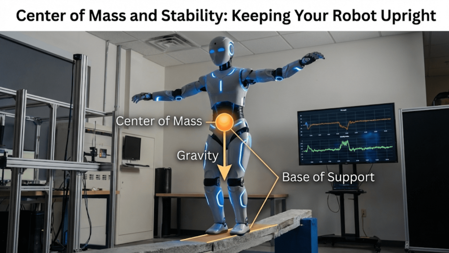
Center of mass represents the average position of all mass in a robot, acting as the single point where gravity’s force appears to concentrate. Stability in robotics depends critically on keeping this center of mass positioned above the robot’s support base, the area enclosed by its contact points with the ground, with wider bases and lower centers of mass producing more stable, tip-resistant designs.
You’ve built your robot carefully, installed powerful motors with appropriate gearing, programmed sophisticated behaviors, and eagerly placed it on the floor for its first test run. It lurches forward enthusiastically, encounters a small bump, and immediately tips over onto its side, motors spinning uselessly in the air. This frustrating scenario plays out in workshops and classrooms worldwide, teaching an essential lesson: a robot that can’t stay upright is a robot that can’t accomplish its mission, regardless of how sophisticated its other systems might be.
Stability isn’t just about avoiding embarrassing tumbles during demonstrations. It fundamentally determines what tasks your robot can attempt, how fast it can move, what terrain it can traverse, and how heavy a payload it can carry. A robot designed without considering center of mass and stability principles will constantly fight against physics, wasting energy maintaining balance and limiting its capabilities. Conversely, a well-designed stable platform allows you to focus on programming, sensing, and task execution rather than constantly worrying whether your robot will tip over.
Understanding center of mass and stability transforms how you approach robot design. Instead of randomly placing components and hoping for the best, you’ll deliberately position heavy elements, calculate stability margins, and make informed trade-offs between competing requirements. Whether you’re building a simple wheeled robot for a school project or designing a sophisticated mobile manipulator, these principles apply universally. The same physics governs a toy robot and an industrial machine—only the scale changes.
Understanding Center of Mass: Where Gravity Pulls
Center of mass (often called center of gravity in everyday language, though technically slightly different) represents a profound simplification of how gravity affects objects. Instead of calculating forces on every particle of your robot separately, you can treat the entire mass as concentrated at one point. This point is where you could theoretically balance your robot on a fingertip if you could position it precisely.
Mathematically, center of mass represents the weighted average position of all mass in an object. If your robot has three components—a 500-gram chassis at position (10, 5) cm, a 200-gram battery at (15, 8) cm, and a 100-gram sensor at (12, 12) cm—you calculate the center of mass by multiplying each mass by its position, summing these products, and dividing by total mass.
For the x-coordinate: CoM_x = (500g × 10cm + 200g × 15cm + 100g × 12cm) ÷ (500g + 200g + 100g) CoM_x = (5000 + 3000 + 1200) ÷ 800 = 9200 ÷ 800 = 11.5 cm
For the y-coordinate: CoM_y = (500g × 5cm + 200g × 8cm + 100g × 12cm) ÷ 800g CoM_y = (2500 + 1600 + 1200) ÷ 800 = 5300 ÷ 800 = 6.625 cm
Your robot’s center of mass sits at position (11.5, 6.625) cm in your coordinate system. This point might not correspond to any actual physical component—it could be empty air in the middle of your chassis—but it’s where gravity effectively acts.
Why does this matter? When your robot accelerates, turns, or encounters slopes, forces act through the center of mass. If you push on your robot’s top, the force creates a rotational effect around the center of mass. Understanding where this point is located helps you predict how your robot will respond to forces and whether it will remain stable or tip over.
The vertical position of the center of mass proves particularly critical for stability. A low center of mass (closer to the ground) makes the robot more stable and resistant to tipping. A high center of mass (far above the ground) makes the robot more prone to toppling, especially during turns or on uneven terrain. This principle explains why sports cars sit low to the ground while tippy vehicles like SUVs have higher centers of mass.
The Support Polygon: Your Stability Foundation
While center of mass tells you where gravity acts, the support polygon defines your robot’s stability boundary. Understanding the relationship between these two concepts is essential for designing robots that stay upright.
The support polygon (also called the base of support) is the area enclosed by connecting all points where your robot contacts the ground. For a simple wheeled robot, imagine drawing lines connecting the centers of all wheels—this polygon is your support base.
For a three-wheeled robot with wheels arranged in a triangle, the support polygon is literally that triangle. For a four-wheeled robot with wheels at the corners of a rectangle, the support polygon is that rectangle. For a six-legged walking robot, the support polygon changes dynamically depending on which legs are touching the ground at any moment.
Here’s the fundamental stability rule: your robot remains stable as long as a vertical line drawn downward from the center of mass falls within the support polygon. If this vertical line exits the support polygon, gravity will create a tipping moment that rotates your robot until it falls over.
Consider a simple example. Your robot is a rectangle 20 cm wide and 30 cm long, with wheels at each corner. The support polygon is a 20 cm × 30 cm rectangle. If your center of mass is located at the geometric center (10 cm from each side, 15 cm from front and back), you’re perfectly centered with excellent stability in all directions.
Now suppose you mount a heavy camera on a tall mast extending 20 cm above the robot’s top surface. This shifts the center of mass upward and slightly forward. The vertical projection of the center of mass still falls within the support polygon, so the robot remains stable when stationary. However, when the robot accelerates forward, inertial forces shift the effective center of mass backward. If this shift moves the vertical projection beyond the rear edge of the support polygon, the robot tips over backward.
The distance from the center of mass projection to the nearest edge of the support polygon is called the stability margin. Larger margins mean more stable robots that can handle greater disturbances before tipping. Smaller margins mean the robot operates closer to its tipping point and will topple from minor disturbances.
Static Versus Dynamic Stability: Different Challenges
Roboticists distinguish between static stability (remaining upright when stationary or moving slowly) and dynamic stability (remaining upright during rapid motion). These require different design approaches and present unique challenges.
Static Stability: The Foundation
Static stability analysis assumes your robot isn’t accelerating—it’s either stationary or moving at constant velocity. Under these conditions, only gravity and support forces matter. The requirement is simple: the center of mass must project inside the support polygon.
For statically stable robots, wider support polygons and lower centers of mass always improve stability. This explains why many industrial robots have broad, heavy bases relative to their working height. The base provides a wide support polygon, while keeping heavy motors and gearboxes low maintains a favorable center of mass position.
Calculating static stability margins is straightforward. Measure the distance from your center of mass projection to each edge of the support polygon. The smallest of these distances is your minimum stability margin. For example:
- Distance to front edge: 8 cm
- Distance to rear edge: 12 cm
- Distance to left edge: 7 cm
- Distance to right edge: 9 cm
Your minimum stability margin is 7 cm (toward the left). This is where your robot will tip first if disturbed in that direction. To improve overall stability, you might shift mass rightward to increase the left margin, though this would decrease the right margin correspondingly.
Dynamic Stability: Motion Matters
When your robot accelerates, turns, or travels on slopes, additional forces come into play. These inertial and gravitational forces effectively shift the position of the center of mass or create additional tipping moments.
During forward acceleration, inertial force acts backward through the center of mass, creating a moment that tries to tip the robot backward. The faster the acceleration, the greater this effect. Similarly, during braking, inertial force acts forward, potentially tipping the robot forward onto its face.
The magnitude of this effect depends on both acceleration and the height of the center of mass above the ground. Higher centers of mass create larger tipping moments for the same acceleration. This is why race cars sit extremely low—it allows aggressive acceleration and braking without flipping over.
Mathematically, the backward shift in effective center of mass during acceleration equals:
Shift distance = (acceleration × center of mass height) ÷ gravitational acceleration
If your robot accelerates at 2 m/s² (about 0.2 g’s) with a center of mass 10 cm above the ground:
Shift = (2 m/s² × 0.10 m) ÷ 9.81 m/s² ≈ 0.020 m = 2 cm
Your effective center of mass shifts backward by 2 cm during this acceleration. If your static stability margin to the rear is only 1.5 cm, you’ll tip over when attempting this acceleration.
Turning creates even more complex dynamics. Centrifugal force acts outward through the center of mass, trying to tip the robot toward the outside of the turn. The faster the turn and the higher the center of mass, the greater this tipping tendency. This is why cars can flip during sharp turns at high speed—the outward force creates a moment strong enough to lift the inside wheels off the ground.
The critical turn speed before tipping can be calculated from:
Critical velocity = √[(track width × gravity) ÷ (2 × center of mass height)]
For a robot with 30 cm track width and 15 cm center of mass height:
Critical velocity = √[(0.30 m × 9.81 m/s²) ÷ (2 × 0.15 m)] Critical velocity = √[2.943 ÷ 0.30] = √9.81 ≈ 3.13 m/s
This robot will tip during turns if its speed exceeds about 3.13 m/s and the turn radius is very tight. Slower speeds or gentler turns remain stable.
Practical Design Strategies for Stability
Understanding the theory is essential, but applying it to create stable robot designs requires practical strategies and design techniques that have proven effective across countless projects.
Strategy 1: Maximize Support Base Width
The simplest and most effective stability improvement is widening your support polygon. Spacing wheels or legs farther apart directly increases stability margins in all directions. However, this comes with trade-offs.
Wider robots require more space to maneuver and may not fit through narrow passages. They also require wider turning circles unless you implement skid steering (where opposite sides rotate in opposite directions). For mobile robots navigating indoor environments, you must balance stability against maneuverability requirements.
A practical approach uses a wheelbase ratio (width to length) appropriate for your application. General-purpose robots often use ratios between 0.6:1 and 1:1. Racing robots might use wider ratios (up to 1.5:1) for maximum turning stability. Robots needing to navigate narrow spaces might use narrower ratios (0.4:1 to 0.6:1), accepting reduced stability in exchange for maneuverability.
Strategy 2: Lower the Center of Mass
Mounting heavy components—batteries, motors, large circuit boards—as low as possible in the chassis dramatically improves stability. Every centimeter you lower the center of mass increases the acceleration and slope angles your robot can handle before tipping.
Compare two designs: Robot A has its 500-gram battery mounted on top of the chassis, placing the center of mass 12 cm above the ground. Robot B mounts the same battery on the chassis bottom, lowering the center of mass to 6 cm. Robot B can handle twice the acceleration before tipping, climb steeper slopes, and execute sharper turns—all from this single change.
When designing your robot chassis, consider component placement during the initial design phase rather than as an afterthought. Create mounting locations for heavy items at the lowest possible positions. If you must mount something high (like a camera for vision), keep it lightweight and consider adding ballast (extra weight) low in the chassis to compensate.
Strategy 3: Add Ballast Strategically
Sometimes your design constraints force you to accept a less-than-ideal center of mass position. Perhaps you need a tall camera mast, or you’re mounting solar panels that must be elevated. In these cases, adding ballast—additional weight positioned strategically—can counterbalance unfavorable weight distribution.
Calculate where your current center of mass is located and where you want it to be. Then determine how much weight you need to add and where to place it to achieve your target. The calculation uses the same center of mass formula worked backward.
For example, your robot’s current center of mass is 12 cm above the ground, and you want to lower it to 9 cm. Your robot weighs 2 kg. You need to add weight at the bottom of the chassis (0 cm height). How much ballast is required?
Let B be the ballast mass. The new center of mass equation becomes:
9 cm = [(2000g × 12cm) + (B × 0cm)] ÷ (2000g + B) 9(2000 + B) = 24000 18000 + 9B = 24000 9B = 6000 B = 667 grams
Adding approximately 667 grams of ballast at the chassis bottom lowers your center of mass from 12 cm to 9 cm, significantly improving stability. The trade-off is increased total weight, requiring more powerful motors and reducing battery life.
Strategy 4: Design for the Worst Case
Don’t design for ideal conditions—design for the most demanding scenarios your robot will encounter. If your robot might climb slopes, calculate stability for your steepest expected slope. If it might carry payloads, calculate with maximum payload positioned in the worst possible location.
A common mistake is designing with the robot empty and on level ground, then being surprised when it tips over when carrying its intended payload or traversing uneven terrain. Add safety factors to your calculations—if calculations show you need 2 cm stability margin, design for 4 cm. This margin accounts for:
- Manufacturing tolerances and assembly variations
- Component weight variations from specifications
- Unexpected loading conditions
- Terrain irregularities
- Dynamic effects not captured in simple calculations
Strategy 5: Consider Dynamic Weight Transfer
During acceleration, braking, and turning, weight transfers between wheels. Understanding this helps you design drivetrains and structure appropriately.
When your robot accelerates forward, weight transfers to the rear wheels—they press harder against the ground while front wheels lighten. This improves rear wheel traction (good for drive wheels at the rear) but can cause front wheels to lift (bad if front wheels are driven or steer the robot).
You can calculate weight transfer using the same principles as tipping analysis. During acceleration, the rearward weight transfer equals:
Weight transfer = (total weight × acceleration × CoM height) ÷ wheelbase
For a 3 kg robot accelerating at 2 m/s² with 10 cm center of mass height and 25 cm wheelbase:
Transfer = (3 kg × 2 m/s² × 0.10 m) ÷ 0.25 m = 0.6 kg-force ÷ 0.25 = 2.4 kg
This seems wrong—how can 3 kg of robot transfer 2.4 kg? The issue is unit confusion. Let’s recalculate properly:
Weight transfer = (mass × acceleration × CoM height) ÷ (gravity × wheelbase) Transfer = (3 kg × 2 m/s² × 0.10 m) ÷ (9.81 m/s² × 0.25 m) Transfer = 0.6 ÷ 2.4525 ≈ 0.24 kg or about 8% of total weight
During this acceleration, rear wheels carry an extra 0.24 kg while front wheels lose 0.24 kg. If your robot has 60/40 weight distribution (1.8 kg front, 1.2 kg rear initially), during acceleration it becomes approximately 1.56 kg front, 1.44 kg rear—much more balanced.
Slopes and Inclines: Gravity’s Challenge
Operating on slopes presents one of the most severe stability challenges. Gravity no longer acts perpendicular to your support base, creating both tipping moments and side-slip tendencies. Understanding slope stability helps you design robots for outdoor operation or uneven terrain.
Longitudinal Stability on Slopes
When climbing or descending slopes, your robot can tip backward (when climbing if center of mass is too far back) or forward (when descending if center of mass is too far forward). The maximum slope angle depends on the center of mass position relative to the support polygon.
For a robot on an incline, tipping occurs when the vertical line through the center of mass passes beyond the support polygon. Geometrically, this creates a relationship between maximum slope angle, center of mass height, and wheelbase.
The maximum climbable slope angle (before tipping backward) is:
tan(angle) = (distance from CoM to rear axle) ÷ (CoM height)
If your center of mass is 10 cm above ground, positioned 15 cm forward of the rear axle:
tan(angle) = 15 cm ÷ 10 cm = 1.5 angle = arctan(1.5) ≈ 56 degrees
This robot can theoretically climb a 56-degree slope before tipping backward. In practice, traction limitations prevent climbing anything approaching this angle, but the calculation establishes an upper bound.
For descending slopes, use the distance from center of mass to front axle:
If center of mass is 12 cm ahead of the rear axle in a 25 cm wheelbase, it’s 13 cm behind the front axle:
tan(angle) = 13 cm ÷ 10 cm = 1.3 angle = arctan(1.3) ≈ 52 degrees
Maximum safe descent angle is 52 degrees before tipping forward.
These calculations assume static conditions. Dynamic effects during actual climbing or descending reduce safe angles considerably. A good rule of thumb is to design for slopes at least twice as steep as you expect to encounter, providing safety margin for dynamic effects and terrain irregularities.
Lateral Stability on Side Slopes
Cross-slopes (where the ground tilts sideways) create lateral tipping risks. The same principles apply, but using track width instead of wheelbase.
Maximum side slope before tipping is:
tan(angle) = (track width ÷ 2) ÷ CoM height
For a robot with 30 cm track width and 10 cm center of mass height:
tan(angle) = 15 cm ÷ 10 cm = 1.5 angle = arctan(1.5) ≈ 56 degrees
This robot can theoretically handle 56-degree side slopes. Again, traction and dynamic factors limit practical capabilities well below this theoretical maximum.
Combined Slopes
Real terrain often presents combined longitudinal and lateral slopes. A hillside might slope both downward and sideways simultaneously. Analyzing these situations requires vector addition of the slope components, with the combined effect often being worse than either individual slope.
For most practical applications, testing on representative terrain provides better guidance than complex calculations for combined slopes. Build your robot with conservative stability margins from calculations, then test incrementally on more challenging terrain to establish actual capabilities.
Multi-Legged Robots: Dynamic Support Polygons
While wheeled robots have fixed support polygons, walking robots create fascinating stability challenges because their support polygon changes continuously as legs lift and plant. Understanding these dynamic considerations is essential for anyone building legged robots.
Static Stability in Walking Robots
A walking robot maintains static stability if its center of mass always projects within the polygon formed by legs currently touching the ground. For a hexapod (six-legged robot), the typical walking gait keeps at least three legs on the ground at all times, forming a triangular support polygon.
During walking, the robot shifts its center of mass to ensure it stays within the new support polygon before lifting any legs. The sequence is:
- Shift weight so center of mass projects well within polygon formed by legs that will remain grounded
- Lift selected legs
- Move lifted legs forward
- Place legs in new positions
- Shift weight forward
- Repeat
This “statically stable” gait is slow but reliable—gravity never provides tipping moments because the center of mass never leaves the support polygon. Insect-inspired hexapods typically use statically stable gaits for reliable walking.
Dynamic Stability in Walking Robots
Faster walking or running requires dynamic stability, where the center of mass may temporarily project outside the support polygon. The robot is momentarily unstable but uses momentum and rapid leg repositioning to avoid falling.
Bipedal robots (two legs, like humans) operate almost entirely with dynamic stability. When you walk, your center of mass projects outside your support polygon during most of the gait cycle—you’re technically falling forward, catching yourself with each step. This allows efficient, fast walking but requires sophisticated control systems and rapid response to disturbances.
The zero moment point (ZMP) concept helps analyze dynamic walking stability. The ZMP is the point on the ground where the net moment from all forces equals zero. For stable walking, the ZMP must remain within the support polygon. Sophisticated walking robots continuously calculate ZMP and adjust leg trajectories to maintain this condition.
Practical Testing and Measurement
Understanding stability theory is valuable, but verifying your robot’s actual stability through testing is essential. Several practical techniques help you measure and improve stability without requiring expensive equipment.
Finding Your Center of Mass Experimentally
If your robot design is too complex for easy calculation, find the center of mass experimentally. The technique uses balance points:
- Balance your robot on a knife edge or narrow support, adjusting until it doesn’t tip either direction
- Mark the balance line on your robot
- Rotate the robot 90 degrees and find the new balance line
- Where the two lines intersect is your center of mass location
For the vertical position, you can use a tilting platform method:
- Place your robot on a platform you can tilt to known angles
- Gradually increase tilt until the robot just begins to tip
- At the tipping point, measure the angle
- Use geometry to calculate center of mass height from the tipping angle and wheelbase
Stability Testing Procedures
Systematically test your robot’s stability under various conditions:
Tilt test: Place the robot on a platform you can tilt in different directions. Gradually increase the angle until tipping occurs. This establishes your actual stability margins and identifies the weakest direction.
Acceleration test: Command maximum forward acceleration and observe whether the robot tips backward. Similarly test braking. If tipping occurs, you need to lower the center of mass, increase wheelbase, or reduce maximum acceleration.
Turn test: Execute progressively tighter turns at various speeds. Note the speed and turn radius where tipping begins. This establishes safe operating envelopes for your control software.
Payload test: Add weights representing maximum intended payload in various positions (worst case is usually high and toward the edge). Verify the robot remains stable and can still perform required tasks.
Slope test: Drive the robot up slopes of increasing angle until tipping occurs or traction is lost (whichever comes first). Test both climbing and descending, as these often have different limits.
Document all test results. They inform control software limits (maximum acceleration, turn speed), operational guidelines (maximum payload position), and design improvements for future versions.
Measurement Tools and Techniques
Several simple tools help you measure stability-related parameters:
Digital level or inclinometer: Measures slope angles accurately. Smartphone apps can serve this purpose.
Digital scale: Weighing components helps calculate center of mass accurately.
Ruler and calipers: Precise measurement of component positions is essential for center of mass calculations.
Camera on tripod: Taking photos from fixed positions helps you measure tipping angles and analyze failure modes.
Create a simple test fixture from plywood that tilts on a hinge. Mark angle measurements on the side. This becomes a reusable tool for consistent tipping angle tests.
Design Trade-offs and Compromises
In real robot design, you rarely optimize solely for stability. Multiple competing requirements create trade-offs you must navigate thoughtfully.
Stability Versus Maneuverability
Wider support polygons improve stability but reduce maneuverability. A robot that needs to navigate narrow spaces or execute tight turns may require a narrower base, accepting reduced stability. Combat robots often choose compact dimensions for maneuverability despite the stability penalty, then use active control systems and driver skill to manage tipping risks.
The solution is often designing the minimum width needed for your operating environment, then maximizing stability within that constraint through low center of mass and optimized component placement.
Stability Versus Ground Clearance
Lowering the center of mass improves stability, but you still need enough ground clearance to traverse obstacles and rough terrain. If your chassis sits too low, it will get stuck on small obstacles despite excellent stability.
The typical compromise uses a low-profile chassis with component mounting optimized for low center of mass, while maintaining adequate clearance through wheel or leg design. Larger-diameter wheels raise the chassis while keeping heavy motors low. Suspension systems can also help, allowing the chassis to remain low during normal driving while providing clearance over obstacles.
Stability Versus Payload Access
Sometimes payload requirements conflict with stability. A robot that must pick up objects benefits from having manipulator hardware high enough to reach various surfaces, but tall manipulators raise the center of mass. Similarly, robots carrying cargo on top have worse stability than those carrying cargo low, but top-loading is often more convenient.
Design solutions include:
- Extendable manipulators that fold down when not in use, lowering the center of mass during travel
- Counterweight systems that automatically balance payload changes
- Wide, low chassis that provides stability margin to accommodate high payloads
- Active stabilization systems using movable ballast or control algorithms
Stability Versus Weight
Adding ballast improves stability but increases weight, requiring more powerful (heavier) motors, larger (heavier) batteries, and stronger (heavier) structure. This can create a negative spiral where added weight demands more weight.
The solution is optimizing component placement before resorting to ballast. Only add ballast when component placement alone can’t achieve required stability. Even then, use the minimum necessary ballast, positioned strategically for maximum effect.
Advanced Concepts: Active Stabilization
Some robots use active systems to maintain stability beyond what passive design achieves. These sophisticated approaches enable capabilities impossible with purely static stability.
Gyroscopic Stabilization
Rapidly spinning gyroscopes resist changes to their orientation, providing stabilizing forces. Some two-wheeled robots use control moment gyroscopes (CMGs) to help maintain balance. These systems work by controlling the gimbal orientation of spinning flywheels—as the gimbal moves, gyroscopic precession creates torques that can counteract tipping moments.
The advantage is achieving stability with minimal support polygon. The disadvantage is added complexity, weight, and power consumption. For most applications, passive stability through good design is preferable, but gyroscopic stabilization enables otherwise impossible configurations like two-wheeled balancing robots.
Reaction Wheels
Similar to gyroscopes, reaction wheels are spinning masses that create corrective torques when their rotation speed changes. Accelerating a reaction wheel creates an opposite reaction torque on the robot body. By controlling multiple reaction wheels on different axes, satellites and some advanced robots maintain orientation without external contact.
These systems require sophisticated control algorithms and significant power, making them suitable primarily for specialized applications where conventional stability approaches won’t work.
Active Suspension
Vehicles and some robots use computer-controlled suspension that adjusts in real-time to maintain stability during dynamic maneuvers. The suspension can shift weight between wheels, lean into turns, or lower the center of mass when high-speed turns are detected.
Formula 1 race cars pioneered active suspension, and some high-end robots implement similar concepts. The complexity and cost generally limit this to professional applications, but the principles inform simpler passive suspension designs.
Tail and Outrigger Systems
Some robots use extending tails or outriggers that deploy when additional stability is needed. A robot with marginal static stability during travel can extend supports when performing tasks that shift the center of mass, like lifting heavy objects with a manipulator.
This provides a nice compromise between compact size during travel and stability during task execution. The mechanism adds complexity but can enable capabilities that wouldn’t otherwise fit within size constraints.
Comparison Table: Stability Approaches and Trade-offs
| Approach | Stability Improvement | Complexity | Weight Impact | Best Applications | Limitations |
|---|---|---|---|---|---|
| Wide Wheelbase | Excellent (proportional to width) | Low | Minimal | General-purpose robots, outdoor vehicles | Reduces maneuverability, larger footprint |
| Low Center of Mass | Excellent (inversely proportional to height) | Low | Minimal | All robots, especially high-speed and slope climbing | May limit ground clearance, payload access |
| Added Ballast | Good (can target specific directions) | Low | High (by definition) | Robots with unavoidable high components | Reduces payload capacity, decreases efficiency |
| Four+ Wheels | Good (larger support polygon) | Low to Medium | Medium | Stable platforms, slow-moving robots | More complex drivetrain than two/three wheels |
| Gyroscopic | Excellent (active correction) | Very High | Medium | Two-wheeled balancers, special platforms | High power consumption, complex control |
| Active Suspension | Excellent (adaptive to conditions) | Very High | Medium to High | High-speed vehicles, dynamic environments | Expensive, requires sophisticated sensors and control |
| Outriggers/Tail | Excellent when deployed | Medium | Low to Medium | Manipulators, intermittent high-stability needs | Adds mechanical complexity, deployment time |
| Tracked Drive | Good (long support polygon) | Medium | Medium | Rough terrain, slope climbing | More complex than wheels, higher friction |
Common Stability Problems and Solutions
Recognizing stability issues and knowing how to address them helps you troubleshoot robots efficiently.
Problem: Robot Tips Backward During Acceleration
Symptoms: Robot lifts front wheels or completely tips over backward when accelerating from rest or speeding up.
Root Cause: Center of mass too far back, too high, or combination; wheelbase too short; acceleration too aggressive for stability margin.
Solutions:
- Move heavy components (especially batteries) forward in the chassis
- Reduce maximum acceleration in control software
- Increase wheelbase (move front wheels farther forward)
- Lower center of mass by mounting components lower
- Add weight to front of robot (last resort due to efficiency impact)
Problem: Robot Tips During Turns
Symptoms: Outside wheels lift during turns, or robot completely tips over in sharp turns.
Root Cause: Center of mass too high; track width too narrow; turn radius too tight for operating speed.
Solutions:
- Lower center of mass by repositioning heavy components
- Widen track width (move wheels farther apart laterally)
- Reduce turn speed in control software
- Implement turn radius limits based on speed
- Add anti-tip sensors that detect wheel lift and reduce speed
Problem: Can’t Climb Slopes Without Tipping
Symptoms: Robot tips backward on inclines well below expected capability; weight shifts excessively during climbs.
Root Cause: Center of mass too far rearward; insufficient forward weight distribution for climbing.
Solutions:
- Shift center of mass forward by moving batteries and heavy components
- Approach slopes at an angle rather than straight on (if terrain allows)
- Lower center of mass to increase tipping angle threshold
- Add temporary ballast to front during slope tests to verify this solves the problem
- Consider tracked drive system for better slope performance
Problem: Unstable With Payload
Symptoms: Robot stable when empty but tips easily when carrying intended payload.
Root Cause: Payload mounting position raises center of mass excessively or shifts it unfavorably; didn’t account for payload in design.
Solutions:
- Redesign payload mounting to be as low and centered as possible
- Add counterweight ballast (if efficiency allows)
- Reduce maximum payload capacity to match actual stability
- Mount payload differently (internal rather than on top, for example)
- Widen support base to accommodate payload-induced center of mass shift
Problem: Tips Forward When Braking
Symptoms: Front wheels dig in and robot nose-dives during emergency stops or aggressive braking.
Root Cause: Center of mass too far forward; braking deceleration too aggressive; front weight bias.
Solutions:
- Shift weight rearward by repositioning components
- Implement gentler deceleration profiles in control software
- Lower center of mass to reduce moment arm of braking force
- Consider anti-lock braking algorithms that prevent wheel lockup
- Add rear weight if necessary (accepting efficiency penalty)
Practical Example: Stability Analysis for a Mobile Robot Platform
Let’s work through a complete stability analysis for a realistic robot project, demonstrating how to apply these principles systematically.
Project Requirements
Design a mobile robot platform for indoor navigation with these specifications:
- Payload capacity: 2 kg (mounted on top surface)
- Must navigate 15-degree ramps
- Must execute 180-degree turns in 1 meter diameter circle
- Maximum speed: 1 m/s
- Must pass through standard 76 cm doorways
Initial Design Parameters
Based on requirements, we select:
- Wheelbase (length): 40 cm
- Track width: 35 cm (fits through doorways with margin)
- Wheel diameter: 15 cm
- Four wheels at corners (static stability)
Component Mass and Positions
List all major components with masses and positions:
| Component | Mass (g) | X Position (cm) | Y Position (cm) | Z Height (cm) |
|---|---|---|---|---|
| Chassis | 800 | 20 | 17.5 | 3 |
| Front left motor | 200 | 5 | 5 | 5 |
| Front right motor | 200 | 5 | 30 | 5 |
| Rear left motor | 200 | 35 | 5 | 5 |
| Rear right motor | 200 | 35 | 30 | 5 |
| Battery | 600 | 25 | 17.5 | 4 |
| Controller | 150 | 15 | 17.5 | 8 |
| Sensors | 100 | 10 | 17.5 | 10 |
| Total | 2450 g |
Calculate Center of Mass
X-coordinate: CoM_x = (800×20 + 200×5 + 200×5 + 200×35 + 200×35 + 600×25 + 150×15 + 100×10) ÷ 2450 CoM_x = (16000 + 1000 + 1000 + 7000 + 7000 + 15000 + 2250 + 1000) ÷ 2450 CoM_x = 50250 ÷ 2450 = 20.5 cm
Y-coordinate: CoM_y = (800×17.5 + 200×5 + 200×30 + 200×5 + 200×30 + 600×17.5 + 150×17.5 + 100×17.5) ÷ 2450 CoM_y = (14000 + 1000 + 6000 + 1000 + 6000 + 10500 + 2625 + 1750) ÷ 2450 CoM_y = 42875 ÷ 2450 = 17.5 cm
Z-coordinate (height): CoM_z = (800×3 + 200×5 + 200×5 + 200×5 + 200×5 + 600×4 + 150×8 + 100×10) ÷ 2450 CoM_z = (2400 + 1000 + 1000 + 1000 + 1000 + 2400 + 1200 + 1000) ÷ 2450 CoM_z = 11000 ÷ 2450 = 4.49 cm
Center of mass position: (20.5, 17.5, 4.49) cm
Evaluate Static Stability
Support polygon: Rectangle from (5, 5) to (35, 30) cm
Stability margins:
- Forward (to front edge at x=5): 20.5 – 5 = 15.5 cm ✓ Excellent
- Rearward (to rear edge at x=35): 35 – 20.5 = 14.5 cm ✓ Excellent
- Left (to left edge at y=5): 17.5 – 5 = 12.5 cm ✓ Good
- Right (to right edge at y=30): 30 – 17.5 = 12.5 cm ✓ Good
Minimum margin: 12.5 cm. This is good for a 35 cm wide robot (36% of track width).
Verify Slope Capability
For 15-degree ramp climbing (longitudinal):
Forward stability margin: 14.5 cm CoM height: 4.49 cm Maximum angle before tipping backward: arctan(14.5/4.49) = arctan(3.23) ≈ 73 degrees ✓
The robot can theoretically climb much steeper than the 15-degree requirement, indicating good design margin.
Verify Turning Stability
For 180-degree turn in 1 m diameter (0.5 m radius) at 1 m/s:
Centrifugal acceleration = v² ÷ r = 1² ÷ 0.5 = 2 m/s²
Lateral load transfer shifts effective CoM by: Shift = (2 m/s² × 0.0449 m) ÷ 9.81 m/s² = 0.009 m = 0.9 cm
This shifts the effective center of mass 0.9 cm toward the outside of the turn. Our lateral stability margin is 12.5 cm, so we have plenty of margin (13.9 times the required amount). ✓
Add Payload
Now add 2 kg payload centered on top surface at height 12 cm:
New total mass: 2450 + 2000 = 4450 g
New Z-coordinate: CoM_z = (11000 + 2000×12) ÷ 4450 = (11000 + 24000) ÷ 4450 = 35000 ÷ 4450 = 7.87 cm
The payload raises center of mass from 4.49 cm to 7.87 cm—a substantial increase.
Re-verify slope climbing with payload: Maximum angle = arctan(14.5 / 7.87) = arctan(1.84) ≈ 61 degrees
Still well above the 15-degree requirement, though margin is reduced. ✓
Re-verify turning with payload: Lateral shift = (2 m/s² × 0.0787 m) ÷ 9.81 m/s² = 0.016 m = 1.6 cm
Stability margin is still 12.5 cm, and shift is 1.6 cm, giving us 7.8× margin. ✓
Design Conclusion
This design meets all stability requirements with good margins even under maximum payload. The center of mass position is well-centered in the support polygon, and the relatively low height (even with payload) provides excellent stability for the intended applications.
Potential improvements:
- Could reduce track width slightly (to perhaps 30 cm) for better doorway clearance while maintaining adequate stability
- Could increase maximum speed safely, as turning stability has substantial margin
- Battery position is good for longitudinal balance but could be moved slightly rearward to perfectly center the unloaded CoM
Conclusion: Building Stable Robots Through Understanding
Stability isn’t an afterthought or a problem to solve when your robot tips over—it’s a fundamental design consideration that should inform every decision from initial concept through final testing. Understanding center of mass and how it interacts with your support polygon transforms you from someone who builds robots that might work into someone who engineers robots that will work.
The principles covered here apply universally, from the simplest three-wheeled line follower to sophisticated legged robots and mobile manipulators. The same physics governs a toy robot and a Mars rover—only the precision of your calculations and the consequences of failure differ in scale. Whether you’re starting your first robotics project or designing your hundredth robot, these stability fundamentals remain relevant.
Begin every design by considering where heavy components will be located. Sketch your intended layout and make a rough estimate of center of mass position. Even crude calculations reveal potential problems while they’re still easy to fix. Position batteries low and centered. Mount motors as low as practical. Keep heavy elements within or near the support polygon rather than cantilevered beyond it.
Test your designs systematically rather than hoping for the best. Use tilt tests, acceleration tests, and slope tests to verify actual stability matches your calculations. When tests reveal problems, use the principles in this article to diagnose root causes rather than applying random fixes. A robot that tips during turns has a different underlying problem than one that tips while climbing slopes, and the solutions differ accordingly.
Accept that stability often conflicts with other design goals, and making good trade-offs separates adequate designs from excellent ones. Sometimes you sacrifice some stability for better maneuverability. Sometimes you accept added weight to achieve required stability margins. Sometimes you choose a larger footprint to maintain stability with high payloads. These trade-offs don’t have universally correct answers—they depend on your specific application and requirements.
As you gain experience, stability analysis becomes intuitive. You’ll look at a robot design and immediately recognize potential tipping problems. You’ll instinctively position heavy components for favorable stability. You’ll design support structures with appropriate margins without detailed calculations. But this intuition builds on the foundation of understanding the underlying principles—center of mass position, support polygon geometry, static versus dynamic effects, and how forces create tipping moments.
Every robot that stays upright when it should represents a design victory where you successfully balanced competing requirements while respecting fundamental physics. Every robot that tips over despite your best efforts teaches valuable lessons about what factors you underestimated or overlooked. Both outcomes advance your understanding, building the experience and intuition that characterizes skilled roboticists.
Master these stability principles, apply them deliberately in your designs, test thoroughly, and you’ll create robots that reliably accomplish their missions rather than spending most of their time lying on their sides. That reliability, more than any sophisticated control algorithm or powerful motor, determines whether your robot succeeds or fails in the real world where physics always wins.