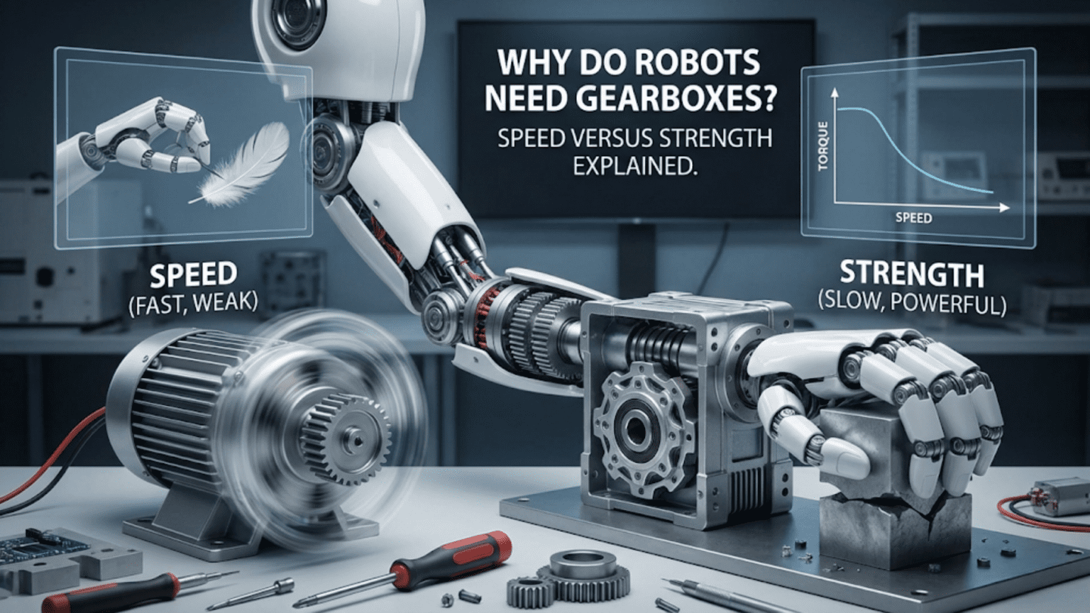
Robots need gearboxes to transform the high-speed, low-torque output of electric motors into the slower, high-torque motion required for practical tasks like lifting objects, climbing slopes, or moving heavy payloads. Gearboxes use interlocking toothed wheels to trade rotational speed for increased force, allowing small motors to perform tasks that would otherwise require much larger, more expensive, and power-hungry alternatives.
If you’ve ever opened up a toy car, a power drill, or looked inside a robot kit, you’ve encountered gearboxes. These assemblies of interlocking wheels with teeth might seem like simple mechanical components, but they represent one of the most crucial elements in robot design. Understanding gearboxes transforms you from someone who assembles robot parts into someone who truly comprehends how to match motors to tasks, optimize performance, and solve real-world robotics challenges.
The fundamental challenge that gearboxes solve is elegant in its simplicity: motors naturally spin fast but produce relatively little twisting force, while robots typically need to move slowly with substantial power. A typical small DC motor might spin at 10,000 revolutions per minute but struggle to lift even a light object. Meanwhile, your robot wheel needs to rotate perhaps 60 times per minute while carrying the entire robot’s weight up a ramp. This mismatch between what motors naturally provide and what robots actually need is where gearboxes become indispensable.
In this comprehensive guide, you’ll learn why this speed-strength trade-off exists, how gearboxes exploit fundamental physics to transform motor characteristics, and most importantly, how to select and apply the right gearing for your specific robotic applications. Whether you’re building your first line-following robot or designing a competition-winning machine, mastering gearbox principles will dramatically improve your results.
The Fundamental Physics: Why Speed and Strength Trade Off
Before diving into practical applications, understanding the underlying physics helps you make informed design decisions rather than just following formulas. The relationship between rotational speed and torque isn’t arbitrary—it emerges from conservation of energy, one of the universe’s most fundamental principles.
Electric motors convert electrical energy into rotational mechanical energy. The power output remains relatively constant across the motor’s operating range, and power equals torque multiplied by rotational speed. This relationship creates an inescapable trade-off: if you want more torque (rotational force), you must accept lower speed, and vice versa. The total energy throughput stays approximately constant.
Think of it like a water wheel. You can have water falling from a great height hitting a small wheel (high speed, low force) or water falling from a shorter height onto a large wheel (low speed, high force). Either way, the total energy transferred is determined by the water flow rate and total height drop. You’re simply choosing how to distribute that energy between force and speed.
In practical terms, when a small motor spins at 12,000 RPM with a torque of 0.05 Nm (Newton-meters), it’s delivering a certain amount of power. If you use gears to reduce the speed to 120 RPM—a 100:1 reduction—you theoretically increase the torque by the same factor to 5 Nm, assuming perfect efficiency. Real gearboxes achieve 70-95% efficiency depending on type and quality, so you’d actually get perhaps 4 Nm at 120 RPM, but the principle holds: you’ve traded speed for dramatically increased strength.
This transformation capability explains why small, lightweight motors can power robots capable of impressive feats. A motor that fits in your palm can, with appropriate gearing, lift loads many times its own weight or propel a robot up steep inclines. Without gearboxes, you’d need motors dozens of times larger and heavier to achieve the same tasks, making most modern robotics applications impractical or impossible.
Understanding Gear Ratios: The Mathematics of Mechanical Advantage
Gear ratios represent the mathematical relationship between input and output in a gearbox system. While the concept might seem abstract initially, gear ratios provide the precise language you need to design robots that actually work as intended rather than just hoping for the best.
A gear ratio is simply the relationship between the number of teeth on the driving gear (connected to your motor) and the driven gear (connected to your wheel or output shaft). If your motor gear has 10 teeth and meshes with a wheel gear having 50 teeth, you have a 5:1 gear ratio. This means the motor must rotate 5 complete revolutions to produce 1 revolution of the output.
The practical implications of this ratio work in three connected ways. First, speed reduction: your output rotates at one-fifth the motor speed. Second, torque multiplication: your output torque becomes approximately five times greater than the motor’s torque (minus friction losses). Third, direction reversal: when gears mesh directly, they rotate in opposite directions, which sometimes matters for your design.
Let’s work through a concrete example using numbers from an actual beginner robot project. Suppose you’re using a standard DC motor rated for 100 RPM at 6V with a stall torque of 0.8 kg·cm (the maximum torque it can produce before stopping). You want your robot wheel to rotate at about 20 RPM to achieve a walking-pace speed. You also need enough torque to climb a 15-degree ramp while carrying the robot’s 2 kg weight.
First, calculate the required gear ratio for speed: 100 RPM ÷ 20 RPM = 5:1. This means you need a gearbox that reduces speed by a factor of five. With this ratio, your output torque becomes: 0.8 kg·cm × 5 = 4 kg·cm (assuming 100% efficiency; in reality, perhaps 3.5 kg·cm accounting for friction).
Next, verify whether this torque suffices for your ramp-climbing requirement. The torque needed depends on wheel radius, robot weight, and incline angle. If your wheels have a 5 cm radius, and you need to overcome gravity pulling your 2 kg robot down the ramp, you can calculate the minimum torque. On a 15-degree slope, the component of weight pulling backward is approximately 2 kg × sin(15°) ≈ 0.52 kg of force. With a 5 cm wheel radius, required torque = 0.52 kg × 5 cm = 2.6 kg·cm per wheel. If you have two driven wheels, each needs 1.3 kg·cm, which your 3.5 kg·cm actual output easily provides.
This calculation process—working backward from your robot’s requirements to determine the necessary gear ratio—represents the fundamental skill in applying gearboxes effectively. Rather than randomly selecting gears or blindly following kit instructions, you’re engineering solutions based on physics and mathematics.
Types of Gearboxes: Choosing the Right Configuration
Different mechanical configurations for gearboxes offer distinct advantages and trade-offs. Understanding these options helps you select appropriate solutions for your specific robotic applications, whether you’re buying pre-assembled gearboxes or designing custom gear trains.
Spur Gears: The Foundation
Spur gears feature straight teeth arranged parallel to the gear’s axis of rotation. These represent the simplest and most common gear type, and you’ll encounter them in most beginner robotics kits. Two spur gears meshing together create a basic gear stage that reverses rotation direction and changes speed/torque according to the tooth count ratio.
The advantages of spur gears include manufacturing simplicity, efficiency (typically 95-98% per stage), and ease of understanding for beginners. You can literally count the teeth and immediately know your gear ratio. The primary disadvantage is noise—the teeth engage abruptly as the gears rotate, creating clicking sounds that worsen at higher speeds. For most educational robots, this proves insignificant, but professional applications often require quieter alternatives.
When designing with spur gears, ensure proper center distance between gear shafts. The gears must mesh with appropriate depth—too shallow and teeth might skip under load; too deep and friction increases while efficiency drops. Most robotics platforms provide mounting holes or brackets that automatically establish correct spacing when you follow assembly instructions.
Planetary Gears: Compact Power
Planetary gear systems pack substantial gear reduction into remarkably small spaces. They work by surrounding a central “sun” gear with multiple “planet” gears, all contained within an outer ring gear. This configuration allows multiple teeth to share the load simultaneously, increasing strength while maintaining compact dimensions.
The key advantage of planetary gearboxes is space efficiency combined with high torque capacity. You can achieve a 5:1 reduction in a package barely larger than the motor itself, whereas achieving the same reduction with spur gears might require a much longer gear train. This makes planetary gearboxes ideal for applications where space is limited, such as robot joints or compact drive systems.
Many commercial servo motors and gearmotors incorporate planetary gearboxes. When you buy a “geared motor” rated for specific RPM and torque, there’s often a planetary gearbox inside providing the reduction. The trade-off is cost—planetary gearboxes are more expensive to manufacture than simple spur gear arrangements—and complexity if you’re building your own rather than buying pre-assembled units.
Worm Gears: Ultimate Reduction and Self-Locking
Worm gearboxes use a threaded shaft (the worm) meshing with a toothed wheel (the worm gear), creating dramatic speed reduction in a single stage. A single-thread worm can achieve reduction ratios of 50:1 or even 100:1, something that would require multiple spur gear stages. Additionally, worm gears exhibit self-locking behavior—the output cannot drive the input backward, which provides inherent braking when the motor isn’t powered.
This self-locking characteristic makes worm gears valuable for robotic arms and lifting mechanisms. When your robot lifts an object and you cut power, a worm gear naturally holds position without requiring continuous motor power or separate brakes. This saves energy and simplifies control systems.
The disadvantages are significant: worm gearboxes typically achieve only 40-60% efficiency, substantially worse than other gear types. This efficiency loss appears as heat and reduced battery life. The high sliding friction also creates more wear, potentially shortening lifespan. Use worm gears when self-locking and high reduction ratios matter more than efficiency, but prefer other types when efficiency is crucial.
Bevel and Miter Gears: Changing Direction
Bevel gears have teeth cut on conical surfaces, allowing them to transmit power between shafts at angles to each other, typically 90 degrees. Miter gears are a special case of bevel gears where both gears have the same number of teeth, creating a 1:1 ratio that simply redirects power without changing speed or torque.
In robotics, bevel gears solve packaging problems. When you need to transmit power from a motor mounted vertically to a horizontal drive shaft (or vice versa), bevel gears handle the directional change cleanly. However, they’re more complex to manufacture and align properly compared to simple spur gears, so beginners typically encounter them less frequently in educational kits.
Gear Ratio Selection: Matching Motors to Tasks
Selecting the appropriate gear ratio represents one of your most important design decisions, directly determining whether your robot can accomplish its intended tasks. Too little reduction and your robot lacks the strength to move; too much reduction and it moves frustratingly slowly. The art and science of gear ratio selection combines calculation, testing, and sometimes educated guessing.
Starting with Requirements
Begin by defining what your robot must do. List specific, measurable requirements rather than vague goals. Instead of “move around,” specify “travel at 0.5 meters per second on flat surfaces and climb 20-degree ramps.” Instead of “pick things up,” define “lift 500 grams to a height of 10 cm within 2 seconds.”
For a mobile robot, key specifications include:
- Desired travel speed (meters per second or RPM)
- Wheel diameter (determines speed-to-RPM conversion)
- Total robot weight including payload
- Maximum incline angle required
- Acceleration requirements (if important)
For a robot arm or lifting mechanism:
- Payload weight
- Lifting speed
- Range of motion
- Precision requirements
Calculating Motor Requirements
Once you have clear requirements, work backward to determine what your motor must provide at the output shaft. Let’s work through a complete example for a wheeled robot.
Suppose you want to build a robot that travels at 0.3 meters per second using wheels with 6 cm diameter. First, calculate required wheel RPM. Wheel circumference = π × diameter = 3.14 × 6 cm ≈ 18.8 cm. At 0.3 m/s = 30 cm/s speed, the wheel completes 30 cm ÷ 18.8 cm ≈ 1.6 rotations per second, or about 96 RPM.
Next, consider torque requirements. Your robot weighs 1.5 kg, and you want it to climb a 20-degree ramp. The force component pulling the robot backward down the ramp is weight × sin(angle) = 1.5 kg × sin(20°) ≈ 0.51 kg-force. With two driven wheels sharing this load, each wheel must overcome about 0.26 kg-force.
Converting to torque: force × radius = 0.26 kg × 3 cm (wheel radius) = 0.78 kg·cm per wheel. Add a safety margin for friction and acceleration—multiply by 1.5 to get about 1.2 kg·cm required output torque per motor.
Now examine your available motor. A common beginner motor might provide 6000 RPM at no load and 1.5 kg·cm stall torque. Your required 96 RPM output is much slower than 6000 RPM, so you definitely need gearing. Calculate the ratio: 6000 RPM ÷ 96 RPM ≈ 62:1.
However, motors don’t provide full stall torque at operating speeds. At 6000 RPM, your motor might only produce 0.3 kg·cm of actual usable torque. With a 62:1 ratio and 85% gearbox efficiency, output torque becomes: 0.3 kg·cm × 62 × 0.85 ≈ 15.8 kg·cm—far exceeding your 1.2 kg·cm requirement. This means you could use a lower gear ratio like 30:1 for faster speed, or stick with 62:1 for better hill-climbing and acceleration.
Common Ratio Ranges by Application
Experience has established typical gear ratio ranges for different robotic applications. These serve as starting points for your calculations:
High-Speed Racing Robots: 10:1 to 30:1 These prioritize speed over torque, assuming flat terrain and lightweight construction.
General-Purpose Mobile Robots: 30:1 to 75:1 Balances speed and torque for varied terrain and reasonable payload capacity.
Heavy-Duty or Climbing Robots: 75:1 to 200:1 Emphasizes torque for steep inclines, heavy payloads, or rough terrain.
Robot Arms and Manipulators: 50:1 to 500:1 High reduction provides precise control and strong holding torque.
Wrist and Gripper Joints: 20:1 to 100:1 Lower reduction for faster motion in lightweight end-effector systems.
These ranges aren’t rigid rules but rather guidelines informed by what works in practice. Your specific requirements might fall outside these ranges—trust your calculations over arbitrary rules.
Practical Implementation: Building and Installing Gearboxes
Understanding theory is essential, but successful robotics requires translating knowledge into physical hardware. Whether you’re assembling a gearbox from a kit, modifying an existing system, or designing a custom solution, practical implementation skills determine whether your robot actually works.
Working with Commercial Gearmotors
The simplest approach for beginners involves buying pre-assembled gearmotors—motors with integrated gearboxes. These units provide known, tested specifications and eliminate the need for custom gear assembly. When shopping for gearmotors, pay attention to these key specifications:
Voltage rating: Must match your power supply and motor driver. Common values include 3V, 6V, 12V, and 24V.
No-load speed: The maximum RPM when no load is attached. Your actual operating speed will be lower.
Rated speed: The speed at normal operating load, typically where the motor provides optimal efficiency.
Stall torque: Maximum torque before the motor stops, but never operate continuously at stall as this damages the motor.
Rated torque: The torque at rated speed, representing normal operating conditions.
Gear ratio: The overall reduction ratio already incorporated in the gearbox.
For example, a specification sheet might read: “12V DC gearmotor, 75:1 ratio, 150 RPM no-load speed, 100 RPM rated speed, 15 kg·cm rated torque, 25 kg·cm stall torque.” This tells you everything needed for design calculations.
When mounting gearmotors to your robot chassis, ensure rigid attachment to prevent vibration and misalignment. Most gearmotors include mounting holes or brackets. Use all provided mounting points rather than just one or two—inadequate mounting allows the motor to flex under load, reducing efficiency and potentially damaging gears.
Coupling Motors to Wheels
Connecting your gearmotor output shaft to wheels requires careful attention to alignment and security. Several coupling methods exist:
Set screw hubs: These slide onto the motor shaft and wheel axle, with small screws tightening against the shaft to prevent slipping. While convenient, they can slip under heavy load. Always use the provided set screws and consider adding thread-locking compound for critical applications.
Clamping hubs: These use compression to grip shafts, providing stronger attachment than set screws. They’re more expensive but worth the investment for robots with high torque requirements.
Direct drive adapters: Some wheels include integrated hubs designed for specific motor shaft sizes. These provide the most reliable connection when available for your components.
Alignment matters critically. If your wheel axis isn’t parallel to your motor shaft, the connection experiences bending stress that wastes energy, creates vibration, and can break under heavy use. Use mounting brackets that ensure parallel alignment, or add flexible couplings that tolerate small misalignments.
Building Custom Gear Trains
For advanced projects or when commercial gearmotors don’t meet your requirements, you might design custom gear trains. This requires access to individual gears, shafts, bearings, and mounting hardware.
Calculate your required reduction ratio first, then select gears that provide it. For large reductions, use multiple stages. For example, to achieve 100:1 reduction, you might use two stages of approximately 10:1 each (like 12-tooth to 120-tooth, then 12-tooth to 120-tooth again).
When designing gear trains, follow these guidelines:
Maintain proper center distance: Gears must mesh with appropriate tooth depth. Too tight causes binding; too loose causes skipping and noise.
Support both ends of shafts: Every shaft carrying gears should have bearings or bushings at both ends to prevent flexing under load.
Consider rotation direction: Each meshing stage reverses direction. Count the stages to ensure your output rotates the correct direction.
Plan for assembly: Design your mounting plate so you can actually insert gears and shafts. Sometimes you need removable side plates or specific assembly sequences.
Use appropriate materials: For low-torque applications, plastic gears work fine and run quietly. For high torque, metal gears provide necessary strength despite being noisier and more expensive.
A simple Arduino code example for testing your geared motor setup:
// Basic gearmotor testing code
const int motorPin1 = 9;  // Motor driver input 1
const int motorPin2 = 10; // Motor driver input 2
const int motorPWM = 11;  // PWM speed control

void setup() {
  pinMode(motorPin1, OUTPUT);
  pinMode(motorPin2, OUTPUT);
  pinMode(motorPWM, OUTPUT);
  Serial.begin(9600);
  Serial.println("Gearmotor Test Program");
}

void loop() {
  // Forward at 50% speed
  digitalWrite(motorPin1, HIGH);
  digitalWrite(motorPin2, LOW);
  analogWrite(motorPWM, 128);  // 50% of 255
  Serial.println("Forward 50%");
  delay(3000);

  // Stop
  digitalWrite(motorPin1, LOW);
  digitalWrite(motorPin2, LOW);
  Serial.println("Stop");
  delay(1000);

  // Reverse at 75% speed
  digitalWrite(motorPin1, LOW);
  digitalWrite(motorPin2, HIGH);
  analogWrite(motorPWM, 191);  // 75% of 255
  Serial.println("Reverse 75%");
  delay(3000);

  // Stop
  digitalWrite(motorPin1, LOW);
  digitalWrite(motorPin2, LOW);
  Serial.println("Stop");
  delay(1000);

  // Forward at 100% speed
  digitalWrite(motorPin1, HIGH);
  digitalWrite(motorPin2, LOW);
  analogWrite(motorPWM, 255);  // 100%
  Serial.println("Forward 100%");
  delay(3000);

  // Stop
  digitalWrite(motorPin1, LOW);
  digitalWrite(motorPin2, LOW);
  Serial.println("Stop");
  delay(5000);
}This test code helps you verify your gearmotor operates correctly at different speeds and can reverse direction. Observe whether the motor runs smoothly at all speeds, listen for unusual noises indicating gear problems, and verify the actual speed matches your expectations based on the gear ratio.
Real-World Examples: Gearboxes in Action
Examining how gearboxes solve problems in actual robot designs helps you internalize these concepts and apply them to your own projects. Let’s explore several real-world scenarios where gear ratio selection made the difference between success and failure.
Example 1: Line-Following Robot Competition
A robotics club wanted to build a line-following robot for a speed competition. Their initial design used motors directly connected to wheels without gearing. The motors spun at 8000 RPM with 0.4 kg·cm torque. With 5 cm diameter wheels, the robot achieved impressive top speed—over 2 meters per second. However, it failed catastrophically when attempting to follow the line.
The problem was insufficient torque for rapid direction changes. When the sensors detected the robot drifting off the line, the control system commanded sharp turns. Without enough torque to quickly accelerate one wheel while slowing the other, the robot overshot corrections and lost the line entirely. Even on straight sections, the robot couldn’t accelerate quickly from the starting line.
The solution involved installing 25:1 gearboxes. This reduced top speed to a more reasonable 0.6 meters per second but multiplied available torque to 10 kg·cm (accounting for efficiency losses). Now the robot could execute sharp turns reliably and accelerate rapidly from stops. They won third place in the competition—fast enough to be competitive but controlled enough to actually follow the course.
This example illustrates that more speed isn’t always better. The gear ratio must match the task requirements, and for a line-following robot, maneuverability and acceleration matter more than ultimate top speed.
Example 2: Stair-Climbing Robot
An engineering team designed a robot capable of climbing standard stairs. Each step presented a 20 cm vertical obstacle—a formidable challenge. Their first prototype used moderate 40:1 gearing, providing what seemed like adequate torque for flat-ground driving and shallow ramps.
When testing on stairs, the robot immediately failed. It could approach the stair base and position itself correctly, but when attempting to lift its front wheels onto the first step, the motors stalled. Calculations revealed the problem: lifting the robot’s front half (1.2 kg) through 20 cm required approximately 24 kg·cm of torque per drive wheel, but their 40:1 gearing only provided 16 kg·cm.
They redesigned with 100:1 planetary gearboxes, accepting slower maximum speed in exchange for 40 kg·cm output torque. The robot successfully climbed stairs, though at a deliberate pace. This project demonstrated the importance of calculating worst-case requirements rather than average conditions. Stair climbing demanded far more torque than normal travel, so the gear ratio needed to accommodate the most demanding scenario.
Example 3: Robotic Arm for Educational Demonstrations
A university outreach program built a robotic arm to demonstrate principles of automation to high school students. The arm needed to pick up small objects (maximum 200 grams) and place them in sorting bins. Initial design used 50:1 gearing on all joints based on generic “robot arm” recommendations found online.
During operation, the shoulder joint (supporting the entire arm weight plus payload) moved smoothly and held position well. However, the wrist joint (moving only the gripper and a light payload) responded sluggishly. Students found the delayed motion frustrating, and precise positioning proved difficult.
Investigation revealed the mismatch: the wrist joint only needed about 2 kg·cm of torque but was geared for 20 kg·cm. This over-gearing made it unnecessarily slow. Replacing the wrist’s 50:1 gearbox with a 20:1 unit improved response time dramatically while still providing adequate strength. The final configuration used 100:1 at the shoulder (high torque for heavy lifting), 50:1 at the elbow (moderate requirements), and 20:1 at the wrist (low load, quick response).
This example demonstrates that different parts of the same robot often need different gear ratios. Match each mechanism to its specific requirements rather than applying one-size-fits-all solutions.
Example 4: Mars Rover Wheel Drives
While most beginners won’t build Mars rovers, examining NASA’s gear ratio decisions for rovers like Curiosity provides valuable insights. These rovers use remarkably high gear ratios—approximately 200:1 in their wheel drive systems. This seems counterintuitive given that rovers move very slowly (maximum speed around 0.15 km/h or 4 cm/s).
The design rationale centers on multiple factors. First, Martian terrain includes steep slopes up to 30 degrees with loose soil, demanding high torque. Second, the rovers operate solar-powered or nuclear-powered electrical systems where energy efficiency matters critically—higher gearing allows motors to operate in their most efficient range. Third, the wheels are quite large (52.5 cm diameter for Curiosity) to traverse obstacles, requiring substantial torque to rotate.
Fourth, and perhaps most interesting, the high gearing provides extremely fine speed control. At 200:1 reduction, each motor revolution translates to very small wheel movement, allowing precise positioning for scientific instrument placement and careful navigation around hazards. While beginners’ robots don’t need Mars rover-level precision, the principle applies: sometimes you choose higher gearing than torque requirements alone would dictate because the resulting speed and control characteristics benefit your application.
Efficiency, Heat, and Longevity: The Hidden Costs of Gearing
Gearboxes aren’t perfect mechanical transformers—they consume some energy through friction, generate heat, and experience wear over time. Understanding these factors helps you design more reliable robots and avoid common pitfalls that lead to premature failures.
Efficiency Losses
Every gear stage consumes some energy through friction between meshing teeth and in the bearings supporting gear shafts. Efficiency varies by gear type:
- Spur gears: 95-98% per stage
- Helical gears: 94-96% per stage
- Bevel gears: 93-96% per stage
- Planetary gears: 90-95% per stage
- Worm gears: 40-90% depending on lead angle
These percentages might seem small, but they multiply through multiple stages. A three-stage spur gearbox achieves approximately 0.97 × 0.97 × 0.97 ≈ 0.91 or 91% overall efficiency. This means 9% of your motor’s power becomes heat rather than useful work. For battery-powered robots, this directly reduces operating time.
Worm gears’ dramatically lower efficiency (often 40-60% for high-ratio worms) means more than half your motor’s energy becomes heat. This makes them inappropriate for applications where battery life matters critically, despite their advantages in reduction ratio and self-locking behavior.
When calculating torque requirements, always account for gearbox efficiency. If you need 10 kg·cm output and your gearbox is 90% efficient, you actually need the motor to provide 10 ÷ 0.90 ≈ 11.1 kg·cm before the gearbox.
Heat Generation and Management
The lost energy in gearboxes appears as heat in the gear teeth, shafts, and bearings. For small hobby robots operating intermittently, this rarely causes problems. However, continuous operation at high loads can generate enough heat to:
- Soften plastic gears, accelerating wear or causing catastrophic failure
- Evaporate lubricant, increasing friction and wear
- Expand metal components, altering gear mesh quality
- Damage nearby electronics if heat spreads through the chassis
Monitor gearbox temperature during extended testing. If gearboxes become uncomfortably hot to touch (over 50°C or 120°F), you’re either overloading the system or have inadequate lubrication. Solutions include:
- Reducing load or duty cycle
- Improving lubrication
- Adding heat sinks or ventilation
- Using more efficient gear types
- Selecting a larger motor/gearbox combination
Professional robots operating continuously often include active cooling for gearboxes, but this adds complexity usually unnecessary for beginner projects.
Wear and Maintenance
Gears gradually wear through the repeated stress of meshing teeth. Harder materials wear more slowly, creating a hierarchy:
- Hardened steel: Extremely durable, thousands of hours
- Mild steel: Moderate durability, hundreds of hours
- Brass: Softer, used for worm gears to protect steel worms
- Plastic: Varies widely by type; nylon lasts longer than ABS
For educational robots that operate intermittently, even plastic gears can last years. Competition robots or those operating many hours daily might need metal gears to survive the season.
Proper lubrication dramatically extends gearbox life. Use appropriate lubricants:
- Plastic gears: Light machine oil or silicone grease
- Metal spur gears: Lithium grease or heavy machine oil
- High-speed gears: Light oil to reduce churning losses
- Worm gears: Heavy grease for pressure resistance
Too much lubricant attracts dirt and creates churning losses. Too little allows metal-on-metal contact and rapid wear. Apply just enough to coat gear teeth with a thin film.
Inspect gears periodically for wear indicators:
- Shiny polished spots on tooth faces (normal light wear)
- Pitting or cracking (excessive stress, replace gears)
- Tooth breakage (catastrophic overload, redesign needed)
- Discoloration (overheating, improve cooling or reduce load)
Comparison Table: Gear Types for Robotics Applications
| Gear Type | Efficiency | Typical Ratio Range | Advantages | Disadvantages | Best Applications |
|---|---|---|---|---|---|
| Spur Gears | 95-98% per stage | 1:1 to 10:1 per stage | Simple, efficient, easy to design, low cost | Noisy, requires multiple stages for high ratios, direction reversal | General-purpose robots, educational projects, wheeled vehicles |
| Planetary Gears | 90-95% per stage | 3:1 to 10:1 per stage | Compact, high torque capacity, multiple contact points | More expensive, complex assembly | Robot joints, compact drive systems, servo motors |
| Worm Gears | 40-90% | 10:1 to 100:1 single stage | Very high ratio, self-locking, compact | Low efficiency, high friction, heat generation | Lifting mechanisms, robot arms, applications requiring holding torque |
| Bevel Gears | 93-96% | 1:1 to 6:1 typical | Changes power direction 90°, smooth operation | Complex alignment, higher cost | Right-angle drives, compact packaging solutions |
| Helical Gears | 94-96% per stage | 1:1 to 10:1 per stage | Quieter than spur, smoother power transfer | Axial thrust requires thrust bearings, more expensive | High-quality robots, commercial products, noise-sensitive applications |
Advanced Considerations: Beyond Basic Gear Ratios
As you gain experience, several advanced topics become relevant for optimizing robot performance and solving complex design challenges.
Multiple Gear Ratios and Transmissions
Some robots benefit from switchable gear ratios—think of a car’s transmission. A robot might use low gearing for climbing steep hills or carrying heavy loads, then shift to high gearing for flat-ground speed. Implementing this requires either a mechanical transmission (complex and heavy for small robots) or multiple motor/gearbox sets that can be engaged selectively.
A simpler alternative uses electronic motor control to simulate multiple ratios. By varying motor voltage or using PWM speed control, you can operate the motor across its speed range. While this doesn’t truly change the torque-speed relationship like mechanical gearing does, it provides practical flexibility. At low PWM values, the motor produces near-stall torque at low speed (like low gear). At high PWM, it approaches maximum speed with less torque available (like high gear).
Compliance and Shock Loading
Rigid gearboxes transfer shocks from impacts or sudden stops directly to motor internals, potentially causing damage. Some applications benefit from compliant elements—springs or flexible couplings between the gearbox and load. These absorb shock forces, protecting delicate components.
Competition robots that frequently collide with obstacles or other robots often include spring-loaded drive systems. When a wheel hits an obstacle, the spring compresses rather than transferring full impact force to gears and motor shaft. This compliance allows the robot to survive impacts that would shred a rigid drivetrain.
The trade-off is reduced precision and more complex control. The compliance introduces elasticity into the system—when you command motion, there’s a slight delay and oscillation as springs compress and rebound. For applications requiring precise positioning, minimizing compliance is important. For rugged, impact-resistant robots, intentional compliance extends lifespan.
Backlash: The Gap Between Gears
Backlash refers to the small amount of play between meshing gear teeth. When you reverse direction, there’s a brief moment where one gear must rotate slightly before re-engaging the other gear’s teeth. This creates a dead zone in control where the motor rotates but the output doesn’t immediately respond.
All gearboxes have some backlash—it’s necessary for manufacturing tolerances and to prevent binding. High-quality gearboxes minimize backlash through precision manufacturing, spring-loaded anti-backlash gears, or preloading mechanisms. Low-cost gearboxes may have substantial backlash.
For mobile robots driving in one direction at a time, backlash is usually insignificant. The gear teeth engage in one direction and stay engaged. However, for applications requiring frequent direction reversals or precise positioning—like robot arms, CNC machines, or control surfaces—excessive backlash causes positioning errors and oscillation.
If your application requires minimal backlash, specify this when selecting gearboxes. “Low-backlash” or “zero-backlash” gearboxes cost more but provide necessary precision. Alternatively, design control systems that account for backlash through calibration and compensation algorithms.
Calculating Acceleration and Dynamic Loads
The previous calculations focused on steady-state conditions—constant speed on constant slopes. Real robots must accelerate, decelerate, and handle dynamic loads. These factors can require substantially more torque than steady operation.
Newton’s second law (F = ma) governs acceleration. To accelerate your robot, motors must provide not only the torque to overcome resistance and gravity but also additional torque to create angular acceleration of wheels. The rotational equivalent is τ = Iα, where τ is torque, I is moment of inertia, and α is angular acceleration.
For a practical example, suppose your 2 kg robot needs to accelerate from 0 to 0.5 m/s in 1 second. The linear acceleration is 0.5 m/s². To find required force: F = ma = 2 kg × 0.5 m/s² = 1 N (Newton). Converting to torque depends on wheel radius—with 5 cm wheels, torque = 1 N × 0.05 m = 0.05 Nm or approximately 0.5 kg·cm per wheel (if two wheels share the load).
This acceleration torque adds to the baseline requirements for overcoming resistance and gravity. If your steady-state requirement was 1.5 kg·cm per wheel, you now need 1.5 + 0.5 = 2.0 kg·cm during acceleration. Using a safety factor, you might design for 2.5-3.0 kg·cm to ensure adequate performance.
Troubleshooting Common Gearbox Problems
Even with careful design, you’ll encounter gearbox-related issues. Recognizing symptoms and understanding root causes helps you solve problems quickly rather than blindly replacing components.
Motor Stalls or Can’t Move Robot
If your motor sounds like it’s straining or stops completely when loaded, you have insufficient torque. Possible causes:
- Gear ratio too low: Solution—increase gear ratio for more torque multiplication
- Motor too small: Solution—use a larger motor or accept reduced loads
- Mechanical binding: Solution—check for obstructions, misalignment, or damaged gears
- Insufficient voltage: Solution—verify battery is charged and motor driver provides adequate voltage
Test by running the motor with no load. If it spins freely, the problem is likely inadequate gearing or too much load. If it still struggles, check for mechanical problems or electrical issues.
Robot Moves Too Slowly
When your robot creeps along despite motors running at full power:
- Gear ratio too high: Solution—reduce gear ratio to trade some torque for speed
- Gearbox friction: Solution—lubricate gears, check for binding or misalignment
- Motor driver limiting current: Solution—verify driver can supply motor’s requirements
- Battery voltage too low: Solution—charge or replace battery
Distinguish between “too slow by design” (wrong gear ratio) and “slower than expected” (friction or electrical problems) by measuring actual motor speed and comparing to specifications.
Excessive Noise or Vibration
Gearboxes naturally make some noise, but loud grinding, clicking, or vibration indicates problems:
- Improper gear mesh: Gears too tight or too loose—adjust center distance
- Damaged teeth: Replace damaged gears
- Loose mounting: Secure motor and gearbox firmly to chassis
- Resonance: Operating at specific speeds that excite mechanical resonances—change speed slightly or add damping material
Metal gears always produce more noise than plastic. If noise is objectionable but gears are functioning properly, consider switching to quieter gear types (helical instead of spur) or adding sound dampening.
Gears Stripping or Breaking Teeth
Catastrophic tooth failure indicates serious overload:
- Gear ratio insufficient for application: Gears can’t handle the torque demanded
- Plastic gears in high-stress application: Switch to metal gears
- Shock loading: Add compliance or limit impact forces
- Manufacturing defects: Replace with higher-quality gears
After gear failure, address the root cause before replacing components, or the new gears will fail similarly. Calculate actual torque demands and ensure your gears are rated for significantly higher values to provide safety margin.
Practical Project: Calculating and Implementing Gearbox Selection
Let’s walk through a complete project from requirements to finished robot, demonstrating how gearbox selection integrates into the overall design process.
Project Goal
Build a robot that can navigate outdoor sidewalks, climb curbs (15 cm height), and carry a 1 kg payload. The robot should travel at walking pace (approximately 1 m/s on flat ground).
Step 1: Define Specifications
- Maximum speed: 1.0 m/s on flat ground
- Payload capacity: 1 kg (plus robot weight, estimated 2 kg empty)
- Obstacle climbing: 15 cm vertical curbs
- Terrain: Concrete sidewalks (some texture but generally smooth)
- Battery: 12V rechargeable (NiMH or LiPo)
Step 2: Select Wheels
For 15 cm obstacles, wheels should be at least 20 cm diameter (obstacles up to 75% of wheel diameter are manageable). Choose 22 cm diameter wheels for safety margin. Larger wheels also handle textured surfaces better and achieve desired speed with lower RPM.
Step 3: Calculate Required Motor Speed
Wheel circumference = π × 22 cm ≈ 69 cm
At 1 m/s = 100 cm/s, rotational speed = 100 ÷ 69 ≈ 1.45 rotations/second = 87 RPM
Step 4: Calculate Required Torque
For curb climbing, the robot must lift its front wheels 15 cm. Assuming weight evenly distributed, front wheels carry approximately 1.5 kg (half of 3 kg total). To lift this weight:
Torque = force × radius = 1.5 kg × 11 cm (wheel radius) = 16.5 kg·cm per front wheel
Add safety factor for friction and dynamic effects: 16.5 × 1.5 = 24.8 kg·cm, round to 25 kg·cm required output torque.
Step 5: Select Motor
Choose a 12V DC motor commonly available for robotics. Specifications:
- No-load speed: 6600 RPM
- Stall torque: 1.2 kg·cm
- Rated voltage: 12V
- Current draw: 0.8A at rated load
Step 6: Calculate Gear Ratio
For speed: 6600 RPM ÷ 87 RPM = 75.9, approximately 76:1 ratio
Check if this provides adequate torque: Motor torque at operating speed is roughly 60% of stall (empirical estimate) = 0.72 kg·cm With 76:1 gearing at 90% efficiency: 0.72 × 76 × 0.90 ≈ 49.2 kg·cm
This exceeds our 25 kg·cm requirement with good safety margin. We could use a slightly lower ratio (like 60:1) for faster top speed while still meeting torque requirements, or stick with 76:1 for extra curb-climbing ability and faster acceleration.
Step 7: Select Commercial Gearmotor or Build Custom
Option A: Purchase 12V DC gearmotor with 75:1 reduction ratio and verify specifications match calculations.
Option B: Build custom using available motor and gears. For 76:1 reduction, possible gear combinations:
- Two stages: 8-tooth to 70-tooth (8.75:1) plus 10-tooth to 87-tooth (8.7:1) = 76:1 overall
- Alternative: Planetary first stage 4:1, followed by spur stage 19:1
Step 8: Implement and Test
Assemble the robot with selected gearmotors, mount wheels securely, and test performance:
- Measure actual top speed on flat ground (should be near 1 m/s)
- Test curb climbing capability with full payload
- Measure battery life during typical operation
- Check motor and gearbox temperatures after extended running
- Listen for unusual noises indicating mechanical problems
Step 9: Iterate if Needed
If testing reveals problems:
- Speed too low: Reduce gear ratio
- Can’t climb curbs: Increase gear ratio or use larger motor
- Overheating: Reduce load or improve cooling
- Battery dies quickly: Improve efficiency or use larger battery
This complete example demonstrates the engineering process: start with clear requirements, calculate what you need, select appropriate components, test thoroughly, and refine based on results. Gearbox selection isn’t an isolated decision—it integrates with wheel size, motor choice, battery capacity, and overall robot architecture.
Conclusion: Mastering the Speed-Strength Trade-off
Gearboxes transform the naturally fast, weak output of motors into the slow, powerful motion that robots actually need. Understanding this speed-versus-strength trade-off moves you beyond blindly following instructions toward deliberately engineering solutions for specific challenges.
The fundamental principles are straightforward: gear ratios multiply torque while dividing speed, different gear types offer specific advantages and trade-offs, and proper selection requires calculating your robot’s actual requirements rather than guessing. Yet applying these principles effectively requires practice, testing, and sometimes accepting that your first design won’t be optimal.
As you build more robots, you’ll develop intuition for appropriate gear ratios. You’ll recognize when a robot seems undergeared (fast but weak) or overgeared (slow but strong) and know how to correct these issues. You’ll understand that the “best” gear ratio depends entirely on application requirements—there’s no universal answer, only solutions optimized for specific tasks.
Start with calculations to get close to optimal values, build your robot, test thoroughly, and don’t hesitate to change gearing if results don’t match expectations. Each project teaches lessons that inform your next design. The robot that couldn’t climb your test ramp teaches you to calculate worst-case scenarios. The competition robot that was fast but uncontrollable teaches you that torque matters for more than just overcoming resistance—it also enables quick direction changes and acceleration.
Gearboxes might seem like simple mechanical devices, but they represent one of the crucial technologies that make modern robotics possible. By mastering gearbox selection and implementation, you gain practical skills that apply across every robotics domain, from hobby projects to industrial automation to space exploration. The Mars rovers use the same fundamental principles as your beginner line-following robot—the scale changes, but the physics and engineering decisions remain remarkably similar.
Whether you’re just starting in robotics or looking to improve existing designs, invest time in understanding gearboxes thoroughly. Calculate your requirements precisely, select appropriate components deliberately, implement them carefully, and test extensively. This disciplined approach, more than any specific gear ratio or motor choice, separates successful robot designs from frustrating failures. The robot that actually works isn’t necessarily the one with the most powerful motor or the highest gear ratio—it’s the one where every component, including the gearbox, was chosen and implemented with understanding and purpose.