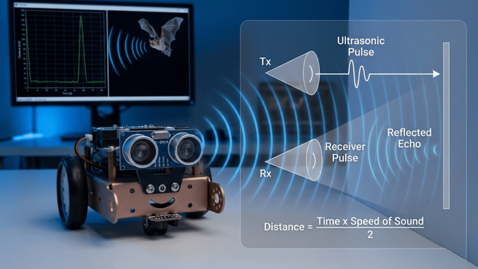
Ultrasonic sensors measure distance by emitting high-frequency sound pulses (above human hearing range at 40 kHz) and timing how long echoes take to return from objects—since sound travels at a known speed (approximately 343 meters per second), measuring the time delay between transmission and echo reception allows precise calculation of object distance, typically accurate from 2 centimeters to 4 meters. This echolocation principle, identical to how bats navigate, provides robots with affordable, reliable obstacle detection and distance measurement capabilities.
Your robot needs to know how far away obstacles are, but cameras are too complex, laser rangefinders are too expensive, and infrared sensors are too short-range or unpredictable. You need something simple, affordable, reliable, and effective—something that works in various lighting conditions, handles different surface types reasonably well, and provides actual distance measurements rather than just binary detection. Ultrasonic sensors solve this problem elegantly, using the same echolocation principle that bats, dolphins, and submarines employ to navigate and detect objects in their environments.
Ultrasonic sensors represent one of the most popular choices for beginner and intermediate robotics projects precisely because they hit the sweet spot of capability versus complexity. They’re inexpensive (often under $5), connect with just four wires, require straightforward code (trigger a pulse, measure echo duration, convert to distance), and provide genuinely useful range measurements for most robot navigation tasks. Whether you’re building an obstacle-avoiding rover, a parking assistant, or a room-mapping robot, ultrasonic sensors likely feature prominently in your design.
This article explains comprehensively how ultrasonic sensors work, from the physics of sound propagation through the electronics that generate and detect ultrasonic pulses, to practical implementation including wiring, programming, troubleshooting, and advanced techniques. You’ll learn not just how to connect a sensor and read values, but why it works this way, what factors affect accuracy, when ultrasonic sensors excel, and when alternative technologies serve better. By understanding these sensors deeply, you’ll use them more effectively and recognize both their capabilities and limitations.
The Physics of Ultrasonic Ranging
Before diving into circuits and code, understanding the underlying physics helps you appreciate how ultrasonic sensors work and why they behave as they do.
What “Ultrasonic” Means
Sound consists of pressure waves traveling through air (or other media). Humans hear frequencies from approximately 20 Hz to 20,000 Hz (20 kHz). Ultrasonic frequencies exceed human hearing range—typically 20 kHz and above. Most ultrasonic sensors used in robotics operate at 40 kHz, well above what humans can perceive.
Why use ultrasonic frequencies?
- Directional propagation: Higher frequencies create narrower beams, improving precision
- Small transducers: Shorter wavelengths allow compact sensor designs
- No audible noise: Operation is silent to humans (though dogs and cats might detect it)
- Less ambient interference: Few natural sources produce 40 kHz tones
The Speed of Sound
Sound travels through air at approximately 343 meters per second (m/s) at 20°C (68°F) at sea level. This speed varies with temperature, humidity, and air pressure, but 343 m/s serves as a reliable approximation for most robotics applications.
Temperature dependence:
- At 0°C: ~331 m/s
- At 20°C: ~343 m/s
- At 30°C: ~349 m/s
For every 1°C temperature increase, sound speed increases approximately 0.6 m/s. In typical indoor environments, temperature variations affect measurements by 1-2%, usually acceptable for robot navigation.
The Time-of-Flight Principle
Ultrasonic ranging uses the time-of-flight (ToF) principle: measure how long a sound pulse takes to travel to an object and return. Since the sound travels to the object and back (round trip), the distance is:
Distance = (Speed of Sound × Time) ÷ 2
Example calculation: Sound pulse returns after 1000 microseconds (0.001 seconds):
- Total distance traveled = 343 m/s × 0.001 s = 0.343 meters
- Actual object distance = 0.343 m ÷ 2 = 0.1715 m = 17.15 cm
The division by 2 accounts for the round trip—sound travels to the object and back.
Simplified Formula for Centimeters
For practical Arduino programming, the formula simplifies to:
Distance (cm) = (Duration in microseconds) ÷ 58
Or equivalently:
Distance (cm) = (Duration in microseconds) × 0.0343 ÷ 2
Where does 58 come from?
- Sound speed: 343 m/s = 34,300 cm/s
- Convert to cm per microsecond: 34,300 cm/s ÷ 1,000,000 µs/s = 0.0343 cm/µs
- Account for round trip: 0.0343 cm/µs ÷ 2 = 0.01715 cm/µs
- Invert for division: 1 ÷ 0.01715 ≈ 58.3 µs per cm (round trip)
So dividing pulse duration (microseconds) by 58 gives distance in centimeters.
HC-SR04: The Standard Ultrasonic Sensor
The HC-SR04 represents the most common ultrasonic sensor in hobby robotics. Understanding its specifications, pinout, and operation prepares you to use it effectively.
HC-SR04 Specifications
Operating voltage: 5V DC Current draw: 15 mA typical Operating frequency: 40 kHz Minimum range: 2 cm (closer objects create timing issues) Maximum range: 400 cm (4 meters) in ideal conditions Typical reliable range: 2-200 cm Measuring angle: ~15 degrees (30-degree cone total) Trigger pulse: 10 microseconds minimum Echo pulse: 150 µs to 25 ms (proportional to distance) Dimensions: 45 mm × 20 mm × 15 mm
Pin Configuration
The HC-SR04 has four pins:
- VCC: Power supply (5V)
- Trig (Trigger): Input signal to start measurement
- Echo: Output signal indicating measured time
- GND: Ground connection
Simple pinout diagram (text representation):
Front view (cylindrical transducers visible):
   [T]   [R]      T = Transmitter (speaker)
                  R = Receiver (microphone)

Pin side view:
VCC | Trig | Echo | GNDHow the HC-SR04 Measures Distance
The measurement sequence follows these steps:
- Trigger pulse: Your code sends a 10-microsecond HIGH pulse to the Trig pin
- Ultrasonic transmission: Sensor generates eight 40 kHz pulses from the transmitter
- Echo wait: Sensor sets Echo pin HIGH and waits for reflected sound
- Echo detection: When reflected sound reaches the receiver, Echo pin goes LOW
- Timing: Duration Echo pin stays HIGH represents round-trip time
- Calculation: Your code measures this duration and calculates distance
The Echo pulse duration directly correlates with distance—longer durations mean farther objects.
Connecting the HC-SR04 to Arduino
Proper wiring ensures reliable operation and prevents damage to components.
Basic Wiring Diagram
Connections:
HC-SR04          Arduino Uno
VCC      →       5V
Trig     →       Digital Pin 9 (or any digital pin)
Echo     →       Digital Pin 10 (or any digital pin)
GND → GNDImportant notes:
- VCC must connect to 5V (not 3.3V)
- Trig and Echo can use any digital pins
- Ensure solid connections (breadboard or soldered)
- Keep wires short for reliable signals
Multiple Sensor Wiring
For robots using multiple ultrasonic sensors:
Shared power:
All VCC pins    →  5V
All GND pins    →  GND
Sensor 1 Trig   →  Pin 9
Sensor 1 Echo   →  Pin 10
Sensor 2 Trig   →  Pin 11
Sensor 2 Echo   →  Pin 12
Sensor 3 Trig   →  Pin 7
Sensor 3 Echo → Pin 8Power considerations: Each sensor draws ~15 mA. Three sensors = ~45 mA total, well within Arduino’s capability. For more than 5-6 sensors, consider external power supply.
Protection Considerations
Voltage protection (if using 3.3V Arduino): Some Arduino boards (Due, Zero) operate at 3.3V logic. The HC-SR04 outputs 5V on Echo pin, potentially damaging 3.3V inputs. Use a voltage divider:
Echo pin → 1kΩ resistor → Arduino input pin
                      ↓
                    2kΩ resistor
                      ↓
GNDThis divider reduces 5V to ~3.3V, protecting the input.
Basic Distance Measurement Code
Let’s start with simple, well-commented code that demonstrates the fundamental measurement process.
Minimal Working Example
// Ultrasonic sensor pins
const int trigPin = 9;
const int echoPin = 10;

// Variables
long duration;
float distance_cm;

void setup() {
  // Initialize pins
  pinMode(trigPin, OUTPUT);
  pinMode(echoPin, INPUT);

  // Initialize serial communication
  Serial.begin(9600);
  Serial.println("Ultrasonic Distance Sensor");
}

void loop() {
  // Clear the trigger pin
  digitalWrite(trigPin, LOW);
  delayMicroseconds(2);

  // Send 10-microsecond trigger pulse
  digitalWrite(trigPin, HIGH);
  delayMicroseconds(10);
  digitalWrite(trigPin, LOW);

  // Measure echo pulse duration (in microseconds)
  duration = pulseIn(echoPin, HIGH);

  // Calculate distance in centimeters
  distance_cm = duration / 58.0;

  // Display result
  Serial.print("Distance: ");
  Serial.print(distance_cm);
  Serial.println(" cm");

  // Wait before next measurement
  delay(100);
}How it works:
- Clear Trig pin (ensure clean start)
- Send 10µs HIGH pulse to Trig pin
- Use
pulseIn()to measure how long Echo pin stays HIGH - Convert duration to distance using division by 58
- Print result
- Repeat every 100ms (10 measurements per second)
Improved Code with Timeout and Error Handling
const int trigPin = 9;
const int echoPin = 10;

// Maximum measurement time (for 4m max range)
const unsigned long timeout = 25000;  // microseconds

void setup() {
  pinMode(trigPin, OUTPUT);
  pinMode(echoPin, INPUT);
  Serial.begin(9600);
}

void loop() {
  float distance = measureDistance();

  if (distance < 0) {
    Serial.println("Error: No echo received");
  } else if (distance < 2) {
    Serial.println("Too close (< 2cm)");
  } else if (distance > 400) {
    Serial.println("Out of range (> 400cm)");
  } else {
    Serial.print("Distance: ");
    Serial.print(distance);
    Serial.println(" cm");
  }

  delay(100);
}

float measureDistance() {
  // Trigger pulse
  digitalWrite(trigPin, LOW);
  delayMicroseconds(2);
  digitalWrite(trigPin, HIGH);
  delayMicroseconds(10);
  digitalWrite(trigPin, LOW);

  // Measure echo with timeout
  long duration = pulseIn(echoPin, HIGH, timeout);

  // Check for timeout (no echo)
  if (duration == 0) {
    return -1;  // Error code
  }

  // Convert to distance
  float distance = duration / 58.0;

  return distance;
}Improvements:
- Timeout prevents indefinite waiting if no echo returns
- Function encapsulates measurement for reusability
- Error checking for common issues
- Clear status messages for different conditions
Multiple Measurements with Averaging
For more stable readings, average multiple measurements:
const int trigPin = 9;
const int echoPin = 10;
const int numReadings = 5;

void loop() {
  float distance = getAverageDistance();

  Serial.print("Average distance: ");
  Serial.print(distance);
  Serial.println(" cm");

  delay(200);
}

float getAverageDistance() {
  float sum = 0;
  int validReadings = 0;

  for (int i = 0; i < numReadings; i++) {
    float reading = measureDistance();

    if (reading > 0 && reading < 400) {
      sum += reading;
      validReadings++;
    }

    delay(10);  // Small delay between readings
  }

  if (validReadings > 0) {
    return sum / validReadings;
  } else {
    return -1;  // No valid readings
  }
}

float measureDistance() {
  digitalWrite(trigPin, LOW);
  delayMicroseconds(2);
  digitalWrite(trigPin, HIGH);
  delayMicroseconds(10);
  digitalWrite(trigPin, LOW);

  long duration = pulseIn(echoPin, HIGH, 25000);

  if (duration == 0) return -1;

  return duration / 58.0;
}This averages five readings, filtering out errors and noise for more reliable results.
Practical Robotics Applications
Ultrasonic sensors enable numerous robot behaviors. Let’s examine complete working examples.
Application 1: Simple Obstacle Avoidance
Robot stops or turns when obstacles are detected:
// Sensor pins
const int trigPin = 9;
const int echoPin = 10;

// Motor pins (example - adjust for your motor driver)
const int motorLeftPin = 5;
const int motorRightPin = 6;

// Thresholds
const float stopDistance = 20.0;    // cm
const float slowDistance = 40.0;    // cm

// Speeds
const int fullSpeed = 200;
const int slowSpeed = 100;

void setup() {
  pinMode(trigPin, OUTPUT);
  pinMode(echoPin, INPUT);
  pinMode(motorLeftPin, OUTPUT);
  pinMode(motorRightPin, OUTPUT);
  Serial.begin(9600);
}

void loop() {
  float distance = measureDistance();

  if (distance < 0) {
    // Measurement error - stop for safety
    stopMotors();
    Serial.println("Sensor error - stopped");
  } else if (distance < stopDistance) {
    // Too close - stop and turn
    stopMotors();
    delay(500);
    turnRight();
    delay(800);
    Serial.println("Obstacle! Turning");
  } else if (distance < slowDistance) {
    // Approaching obstacle - slow down
    setMotors(slowSpeed);
    Serial.print("Slowing - Distance: ");
    Serial.println(distance);
  } else {
    // Path clear - full speed
    setMotors(fullSpeed);
    Serial.print("Clear - Distance: ");
    Serial.println(distance);
  }

  delay(50);
}

float measureDistance() {
  digitalWrite(trigPin, LOW);
  delayMicroseconds(2);
  digitalWrite(trigPin, HIGH);
  delayMicroseconds(10);
  digitalWrite(trigPin, LOW);

  long duration = pulseIn(echoPin, HIGH, 25000);
  if (duration == 0) return -1;
  return duration / 58.0;
}

void setMotors(int speed) {
  analogWrite(motorLeftPin, speed);
  analogWrite(motorRightPin, speed);
}

void stopMotors() {
  analogWrite(motorLeftPin, 0);
  analogWrite(motorRightPin, 0);
}

void turnRight() {
  analogWrite(motorLeftPin, 150);
  analogWrite(motorRightPin, 0);
}Application 2: Wall-Following Robot
Maintain constant distance from a side wall:
const int trigPin = 9;
const int echoPin = 10;
const int motorLeftPin = 5;
const int motorRightPin = 6;

const float targetDistance = 25.0;  // Desired wall distance (cm)
const int baseSpeed = 150;
const float Kp = 3.0;  // Proportional gain for steering

void loop() {
  float wallDistance = measureDistance();

  if (wallDistance > 0 && wallDistance < 100) {
    // Calculate error (positive = too far, negative = too close)
    float error = targetDistance - wallDistance;

    // Calculate steering correction
    int steeringCorrection = Kp * error;

    // Adjust motor speeds (turn toward wall if too far)
    int leftSpeed = baseSpeed - steeringCorrection;
    int rightSpeed = baseSpeed + steeringCorrection;

    // Constrain to valid range
    leftSpeed = constrain(leftSpeed, 0, 255);
    rightSpeed = constrain(rightSpeed, 0, 255);

    analogWrite(motorLeftPin, leftSpeed);
    analogWrite(motorRightPin, rightSpeed);

    Serial.print("Wall: ");
    Serial.print(wallDistance);
    Serial.print(" cm, Error: ");
    Serial.print(error);
    Serial.print(", Motors: L=");
    Serial.print(leftSpeed);
    Serial.print(" R=");
    Serial.println(rightSpeed);
  } else {
    // Lost wall - stop and search
    stopMotors();
    Serial.println("Wall lost!");
  }

  delay(50);
}

float measureDistance() {
  digitalWrite(trigPin, LOW);
  delayMicroseconds(2);
  digitalWrite(trigPin, HIGH);
  delayMicroseconds(10);
  digitalWrite(trigPin, LOW);

  long duration = pulseIn(echoPin, HIGH, 25000);
  if (duration == 0) return -1;
  return duration / 58.0;
}

void stopMotors() {
  analogWrite(motorLeftPin, 0);
  analogWrite(motorRightPin, 0);
}Application 3: Three-Sensor Navigation
Using front, left, and right sensors for intelligent navigation:
// Sensor pins
const int frontTrig = 9, frontEcho = 10;
const int leftTrig = 7, leftEcho = 8;
const int rightTrig = 11, rightEcho = 12;

// Motor pins
const int motorLeft = 5, motorRight = 6;

void setup() {
  pinMode(frontTrig, OUTPUT);
  pinMode(frontEcho, INPUT);
  pinMode(leftTrig, OUTPUT);
  pinMode(leftEcho, INPUT);
  pinMode(rightTrig, OUTPUT);
  pinMode(rightEcho, INPUT);
  pinMode(motorLeft, OUTPUT);
  pinMode(motorRight, OUTPUT);
  Serial.begin(9600);
}

void loop() {
  // Read all sensors
  float frontDist = measure(frontTrig, frontEcho);
  float leftDist = measure(leftTrig, leftEcho);
  float rightDist = measure(rightTrig, rightEcho);

  // Debug output
  Serial.print("F:");
  Serial.print(frontDist);
  Serial.print(" L:");
  Serial.print(leftDist);
  Serial.print(" R:");
  Serial.println(rightDist);

  // Decision logic
  if (frontDist < 30) {
    // Obstacle ahead - choose direction based on side sensors
    if (rightDist > leftDist && rightDist > 30) {
      Serial.println("Turning RIGHT");
      turnRight();
    } else if (leftDist > 30) {
      Serial.println("Turning LEFT");
      turnLeft();
    } else {
      Serial.println("BLOCKED - Backing up");
      backUp();
    }
  } else {
    // Path clear - move forward
    Serial.println("Forward");
    moveForward();
  }

  delay(100);
}

float measure(int trigPin, int echoPin) {
  digitalWrite(trigPin, LOW);
  delayMicroseconds(2);
  digitalWrite(trigPin, HIGH);
  delayMicroseconds(10);
  digitalWrite(trigPin, LOW);

  long duration = pulseIn(echoPin, HIGH, 25000);
  if (duration == 0) return 999;  // Return large value if no echo
  return duration / 58.0;
}

void moveForward() {
  analogWrite(motorLeft, 180);
  analogWrite(motorRight, 180);
}

void turnRight() {
  analogWrite(motorLeft, 150);
  analogWrite(motorRight, 0);
  delay(500);
}

void turnLeft() {
  analogWrite(motorLeft, 0);
  analogWrite(motorRight, 150);
  delay(500);
}

void backUp() {
  // Note: Requires H-bridge or reversible motor driver
  analogWrite(motorLeft, -150);
  analogWrite(motorRight, -150);
  delay(300);
}Factors Affecting Accuracy and Reliability
Understanding what influences ultrasonic sensor performance helps you design robust systems and troubleshoot problems.
Surface Material and Angle
Hard, smooth surfaces: Reflect sound well (walls, cardboard, metal) Soft, absorbent materials: Absorb sound, reducing echo strength (foam, fabric, carpet) Irregular surfaces: Scatter sound in multiple directions (bushes, complex shapes) Angled surfaces: Reflect sound away from sensor if angle is too steep
Best practice: For reliable detection, approach surfaces as close to perpendicular (90 degrees) as possible. Angled approaches may not return echoes.
Temperature Effects
Sound speed changes with temperature (~0.6 m/s per °C). In practice:
- Indoor environments: ±2°C variation → ±1% distance error (usually acceptable)
- Outdoor extremes: 0°C to 40°C → ~5% distance variation
- For precision applications: Measure temperature and compensate
Temperature compensation formula:
float compensatedSpeed = 331.3 + (0.606 * temperature_celsius);
float distance = (duration * compensatedSpeed / 2.0) / 10000.0; // cmMultiple Sensor Interference
When using multiple ultrasonic sensors, they can interfere if operating simultaneously (one sensor’s echo triggers another sensor’s receiver).
Solutions:
- Sequential operation: Measure sensors one at a time with delays
- Different frequencies: Use sensors operating at different frequencies (if available)
- Physical separation: Mount sensors far apart and aimed in different directions
Sequential measurement example:
delay(50);  // Wait for previous echoes to dissipate
float dist1 = measure(trig1, echo1);
delay(50);
float dist2 = measure(trig2, echo2);
delay(50);
float dist3 = measure(trig3, echo3);Minimum Range Limitations
The ~2 cm minimum range exists because:
- Transmitter and receiver are physically separated
- Initial pulse “rings” briefly before settling
- Electronics need time to switch from transmit to receive mode
Objects closer than 2 cm either aren’t detected or give unstable readings.
Maximum Range Limitations
Beyond 4 meters (HC-SR04 limit), several factors reduce reliability:
- Echo signal becomes very weak
- Ambient noise comparable to echo signal
- Beam spreading reduces returned echo
- Timeout prevents indefinite waiting
For robotics, 2-200 cm represents the reliable operating range.
Environmental Factors
Wind: Affects sound propagation speed and direction (outdoor robots) Humidity: Slight effect on sound speed (usually negligible) Air pressure: Affects sound speed (significant only at extreme altitudes) Ambient noise: Loud 40 kHz sources could interfere (rare)
Advanced Techniques and Optimizations
Beyond basic distance measurement, several techniques enhance ultrasonic sensor utility.
Median Filtering for Noise Reduction
Instead of averaging, use median filtering to reject outliers:
const int numReadings = 5;

float getMedianDistance() {
  float readings[numReadings];

  // Collect readings
  for (int i = 0; i < numReadings; i++) {
    readings[i] = measureDistance();
    delay(10);
  }

  // Sort array
  for (int i = 0; i < numReadings - 1; i++) {
    for (int j = i + 1; j < numReadings; j++) {
      if (readings[j] < readings[i]) {
        float temp = readings[i];
        readings[i] = readings[j];
        readings[j] = temp;
      }
    }
  }

  // Return middle value
  return readings[numReadings / 2];
}Median filtering is more robust against occasional spurious readings than averaging.
Kalman Filtering
For advanced applications, implement Kalman filtering for optimal noise reduction and prediction:
// Simplified Kalman filter for distance measurement
class KalmanFilter {
  private:
    float q;  // Process noise
    float r;  // Measurement noise
    float x;  // Estimated value
    float p;  // Estimation error
    float k;  // Kalman gain

  public:
    KalmanFilter(float process_noise, float measurement_noise) {
      q = process_noise;
      r = measurement_noise;
      x = 0;
      p = 1;
    }

    float update(float measurement) {
      // Prediction
      p = p + q;

      // Update
      k = p / (p + r);
      x = x + k * (measurement - x);
      p = (1 - k) * p;

      return x;
    }
};

KalmanFilter kf(0.1, 2.0);  // Tune these values

void loop() {
  float rawDistance = measureDistance();
  float filteredDistance = kf.update(rawDistance);

  Serial.print("Raw: ");
  Serial.print(rawDistance);
  Serial.print(" cm, Filtered: ");
  Serial.print(filteredDistance);
  Serial.println(" cm");

  delay(50);
}Mapping and Grid Building
Use ultrasonic sensors to create simple environment maps:
const int numAngles = 18;  // Sweep in 20-degree increments
float distanceMap[numAngles];

void scanEnvironment() {
  for (int angle = 0; angle < numAngles; angle++) {
    // Set servo to angle (if using rotating sensor)
    setServoAngle(angle * 20);
    delay(100);  // Wait for servo to settle

    // Measure distance at this angle
    distanceMap[angle] = getMedianDistance();

    Serial.print("Angle ");
    Serial.print(angle * 20);
    Serial.print(": ");
    Serial.print(distanceMap[angle]);
    Serial.println(" cm");
  }
}

void findClearestDirection() {
  float maxDistance = 0;
  int bestAngle = 0;

  for (int i = 0; i < numAngles; i++) {
    if (distanceMap[i] > maxDistance) {
      maxDistance = distanceMap[i];
      bestAngle = i * 20;
    }
  }

  Serial.print("Clearest path at ");
  Serial.print(bestAngle);
  Serial.println(" degrees");
}Rate of Change (Velocity Estimation)
Estimate object approach/recede velocity:
float previousDistance = 0;
unsigned long previousTime = 0;

void loop() {
  float currentDistance = measureDistance();
  unsigned long currentTime = millis();

  if (previousTime > 0) {
    float deltaDistance = currentDistance - previousDistance;
    float deltaTime = (currentTime - previousTime) / 1000.0;  // seconds

    float velocity = deltaDistance / deltaTime;  // cm/s

    Serial.print("Distance: ");
    Serial.print(currentDistance);
    Serial.print(" cm, Velocity: ");
    Serial.print(velocity);
    Serial.println(" cm/s");

    if (velocity < -10) {
      Serial.println("WARNING: Object approaching quickly!");
    }
  }

  previousDistance = currentDistance;
  previousTime = currentTime;

  delay(100);
}Negative velocity indicates approaching objects; positive indicates receding.
Comparison Table: Distance Sensing Technologies
| Technology | Range | Accuracy | Cost | Light Sensitivity | Surface Dependency | Best For |
|---|---|---|---|---|---|---|
| Ultrasonic (HC-SR04) | 2-400 cm | ±1-3 cm | $2-5 | None | Moderate | General navigation, obstacle avoidance |
| Infrared (Sharp GP2Y0A) | 10-80 cm | ±0.5-2 cm | $10-15 | High | High | Precise short-range, reflective surfaces |
| Time-of-Flight Laser (VL53L0X) | 5-200 cm | ±1-3 mm | $5-10 | Low | Low | Precision measurement, dark surfaces |
| LIDAR (RPLidar A1) | 15-1200 cm | ±1-5 cm | $100-400 | None | Low | Mapping, 360° scanning, advanced navigation |
| Sonar (Maxbotix) | 20-765 cm | ±1-2.5 cm | $30-80 | None | Low | Outdoor, weather-resistant, long-range |
| Camera + Computer Vision | Variable | Variable | $20-200+ | Required | Variable | Object recognition, complex navigation |
Troubleshooting Common Problems
Even properly wired sensors can exhibit problems. Systematic troubleshooting resolves most issues.
Problem: No Readings (Always Returns 0 or Timeout)
Symptoms: pulseIn() times out; distance always shows error.
Possible Causes:
- Wiring incorrect (wrong pins, loose connections)
- Insufficient power supply
- Damaged sensor
- No reflective surface in range
Solutions:
- Verify all four connections (VCC, Trig, Echo, GND)
- Check pin numbers in code match physical connections
- Test with a large flat surface (wall, book) within 50 cm
- Measure voltage at VCC pin (should be 5V ±0.25V)
- Try different digital pins
- Test sensor on known-working setup
Problem: Erratic or Noisy Readings
Symptoms: Values jump randomly; readings unstable; fluctuates ±10 cm.
Possible Causes:
- Electrical noise from motors
- Soft or angled surfaces
- Multiple sensors interfering
- Loose breadboard connections
Solutions:
- Add median filtering or averaging (shown in code examples)
- Separate sensor power from motor power
- Test with hard, flat, perpendicular surface
- Add delay between sensor readings if using multiple sensors
- Solder connections instead of breadboard
- Add capacitors across power pins (100µF electrolytic + 0.1µF ceramic)
Problem: Readings Stuck at Maximum Range
Symptoms: Always returns ~400 cm regardless of objects.
Possible Causes:
- Echo pin not connected
- Receiver damaged or blocked
- Absorptive surface (no echo returns)
Solutions:
- Verify Echo pin wiring
- Visually inspect receiver (clean if dusty)
- Test with strong reflector (metal sheet, mirror)
- Check Echo pin voltage with multimeter during operation
Problem: Minimum Range Issues
Symptoms: Can’t detect objects closer than 10-15 cm; close objects give maximum range reading.
Possible Causes:
- Sensor design limitation (normal for very close objects)
- Code timeout too short
- Objects directly against sensor
Solutions:
- Accept ~2 cm minimum as normal limitation
- For close-range detection, use infrared or contact sensors
- Increase timeout value in
pulseIn() - Position sensor so objects can’t touch transducers
Problem: Inconsistent Readings at Specific Distances
Symptoms: Reliable at some distances, erratic at others.
Possible Causes:
- Standing wave interference at specific distances
- Surface angle causes echo to reflect away
- Surface material changes at that distance
Solutions:
- Average multiple measurements
- Change sensor mounting angle
- Accept occasional outliers; use median filtering
- Understand this is characteristic of specific environments
Conclusion: Ultrasonic Sensors as the Robotic Sense of Proximity
Ultrasonic sensors provide robots with a crucial capability: knowing how far away objects are before colliding with them. This distance awareness enables autonomous navigation, obstacle avoidance, mapping, and countless other behaviors impossible with simpler sensors. While not perfect—limitations include minimum range, sensitivity to surface properties, and moderate precision—ultrasonic sensors hit the optimal balance of cost, simplicity, and capability for most hobby and educational robotics.
The HC-SR04 in particular has become a standard precisely because it works well enough for most applications while remaining affordable and easy to use. Four simple wires, a few lines of code, and you have working distance measurement. This accessibility makes ultrasonic ranging an excellent introduction to sensor integration while providing genuinely useful functionality in practical robots.
The skills you’ve developed in this article—understanding time-of-flight principles, connecting sensors properly, writing measurement code, filtering noise, combining multiple sensors, and troubleshooting problems—transfer directly to other sensors and more complex projects. Whether you’re building your first obstacle-avoiding robot or designing sophisticated autonomous systems, the principles remain constant: trigger measurement, read response, convert to meaningful units, filter noise, make decisions based on data.
Start simple: connect a single sensor, read distances, display values. As this becomes comfortable, add complexity: multiple sensors for broader coverage, filtering for stable readings, control loops that respond to distance measurements, mapping algorithms that build environment models. Each project deepens understanding and reveals new applications.
Remember that sensors are tools, each with strengths and weaknesses. Ultrasonic sensors excel at general-purpose distance measurement in controlled environments but struggle with soft surfaces and very close or very distant objects. Recognize these limitations and combine ultrasonic sensing with other sensor types—infrared for close precision, vision for object identification, encoders for position tracking. Multi-sensor fusion creates robust systems that compensate for individual sensor weaknesses.
Most importantly, ultrasonic sensors demonstrate a fundamental robotics principle: robots perceive the world not through human senses but through specialized instruments that convert physical phenomena into electrical signals. Understanding how these sensors work—the physics, electronics, and signal processing—transforms you from someone who uses sensors blindly into someone who chooses and applies them effectively. Master ultrasonic ranging, and you’ve mastered an essential tool in the robotics sensory toolkit.