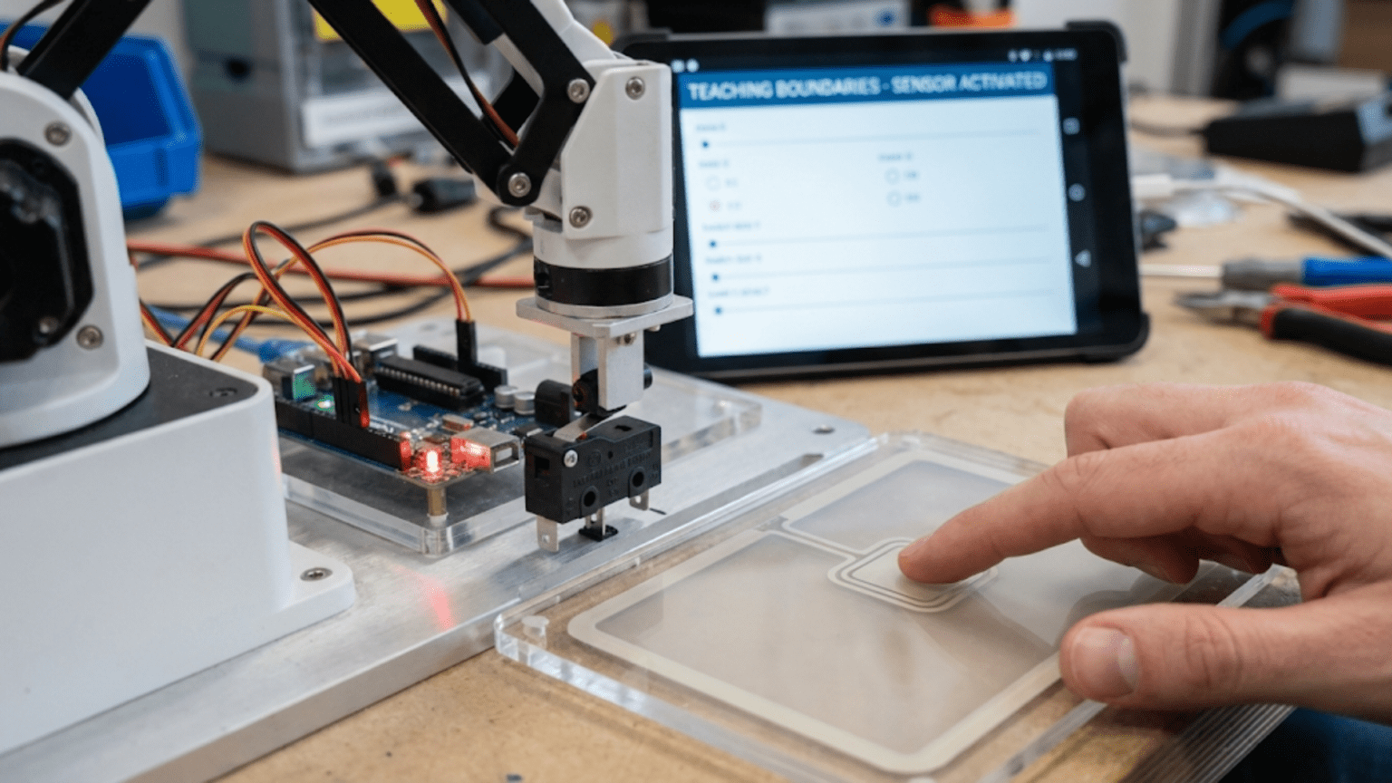
Touch sensors and limit switches are contact-based sensors that detect physical contact or mechanical boundaries by completing or breaking an electrical circuit when pressed, giving robots the ability to detect collisions, find precise reference positions through homing routines, prevent mechanical over-travel that could damage motors and structures, and confirm that gripper fingers have made contact with objects. Unlike proximity sensors that detect objects at a distance, touch sensors provide absolute certainty of physical contact—making them indispensable for safety-critical robot functions and reliable position referencing.
Your robot arm sweeps toward its home position, motors driving confidently toward what the program believes is a safe limit. But accumulated position errors, a slightly different starting pose, or a mechanical slip mean the arm is already two centimeters past where the code thinks it is. The motor continues pushing against the mechanical hard stop, grinding gears and straining servos, until something breaks or the power supply trips. A single limit switch at that boundary, costing less than fifty cents, would have stopped the motion the instant contact occurred—preventing damage, protecting motors, and flagging the position error for correction.
This scenario plays out in robotics projects of all scales. Industrial robot arms use dozens of limit switches. CNC machines depend on them for homing. 3D printers use them to find their origin. Elevator systems rely on them for floor detection. Even simple obstacle-avoiding rovers benefit enormously from physical bump sensors that provide absolute, unambiguous confirmation of contact—something no proximity sensor can fully replicate at very close distances. Touch sensors and limit switches represent one of the oldest, most reliable, and most underutilized sensing technologies in hobby robotics.
This article covers the full spectrum of contact sensing: the physics and mechanics of switches and bump sensors, how to wire them correctly (including the critical role of pull-up resistors and debouncing), how to implement reliable detection code, and how to use contact sensing for the most important robotics applications—collision detection, homing routines, gripper feedback, and mechanical safety interlocks. By understanding contact sensing thoroughly, you add a level of physical awareness and safety to your robots that no other sensing technology provides quite as simply or reliably.
How Switches Work: The Physics of Contact
Understanding the mechanical and electrical operation of switches prevents wiring mistakes and debugging confusion.
The Basic Switch Circuit
A switch is the simplest possible sensor: two electrical contacts that either touch (circuit closed, current flows) or don’t touch (circuit open, no current). Your microcontroller reads this as a digital signal—HIGH when current flows, LOW when it doesn’t, or vice versa depending on your circuit configuration.
Normally Open (NO) contacts: In the default (unactivated) state, the contacts are separated—no current flows. Pressing the switch pushes the contacts together, completing the circuit. Most pushbuttons use NO contacts.
Normally Closed (NC) contacts: In the default state, the contacts touch—current flows. Pressing the switch separates the contacts, breaking the circuit. NC contacts are preferred for safety applications because a broken wire or failed switch produces the same signal as activation—a fail-safe behavior.
Common (COM) terminal: Many switches have three terminals: NO, NC, and COM (common). COM is always connected; NO completes the circuit to COM when activated; NC completes the circuit to COM when NOT activated.
Limit Switch Mechanics
Limit switches designed for robotics and industrial use contain a spring-loaded mechanism with an actuator that translates motion into contact opening or closing. The actuator style determines how the switch responds:
Plunger actuators: A simple push-button style—requires direct linear force against the button. Common for end-stops in 3D printers.
Lever actuators: A lever arm amplifies force and changes the force direction—a small lateral force on the lever tip activates the switch. Useful for detecting rotating components.
Roller lever actuators: Same as lever but with a roller tip that smoothly rolls over cam surfaces. Reduces wear for high-cycle applications.
Whisker/wire actuators: A flexible wire that deflects in multiple directions—useful for detecting objects from any angle. Popular for robot bump bumpers.
The Bounce Problem
When switch contacts meet or separate, they don’t do so cleanly. The metal contacts physically bounce off each other multiple times before settling into a stable state—each bounce represents a false open/close transition.
Timeline of a button press:
Milliseconds:  0    1    2    3    4    5    6    7    8
Button state:  O    C   O C  O C   C    C    C    C    C
(O=Open, C=Closed - bouncing during ms 1-5)Your microcontroller, reading thousands of times per second, sees this bouncing as multiple rapid press-and-release events. Without debouncing, a single button press might register as 5-20 separate events—catastrophic for counting, toggling, or any application expecting exactly one event per physical press.
Bouncing characteristics:
- Duration: Typically 1-20 milliseconds for mechanical switches
- Frequency: Can produce 10-100 false transitions
- Variability: Each press produces different bounce patterns
Both hardware and software solutions exist for debouncing, covered in detail in the implementation section.
Types of Contact Sensors in Robotics
Different applications call for different contact sensor types. Understanding the options helps you choose appropriately.
Tactile Pushbuttons
Small PCB-mount buttons designed for light-duty, low-cycle applications. Common in electronics projects for user input.
Characteristics:
- Contact force: 100-400 grams
- Contact travel: 0.1-0.5 mm
- Cycle life: ~100,000 operations
- Cost: $0.05-0.50
Robotics uses:
- Start/stop buttons on robot chassis
- Mode selection
- Emergency stop (momentary)
- User interface
Not ideal for:
- Detecting robot collisions (too fragile)
- High-cycle mechanical applications
- Outdoor or wet environments
Snap-Action Limit Switches
Purpose-built for mechanical boundary detection. Use a snap-action mechanism (bistable spring) that produces a clean, fast contact transition.
Characteristics:
- Contact force: 50-500 grams depending on model
- Contact travel: Up to 5 mm pretravel, very short overtravel
- Cycle life: 1-10 million operations
- Cost: $1-5
Common models:
- SS-5GL: Small, inexpensive, lever actuator
- V-156-1A5: Standard industrial snap-action switch
- KW12-3: Very common in 3D printers and hobby CNC
Robotics uses:
- End-stop detection for CNC and 3D printers
- Robot arm joint limits
- Drawer and door position detection
- Conveyor end detection
Bump Sensors / Whisker Sensors
Flexible wire or spring “whiskers” mounted on the robot’s exterior detect contact from any direction before the main chassis makes contact.
Characteristics:
- Detection range: 5-30 cm ahead of chassis (depending on whisker length)
- Omnidirectional: Detect contact from multiple angles
- Mechanical simplicity: Spring wire connecting to switch contact
- Cost: $1-10 for complete assembly
Robotics uses:
- Collision detection in obstacle-avoiding robots
- Wall-following contact confirmation
- Multi-directional bump detection
DIY whisker construction:
Stiff wire (piano wire or similar)
  └── Bent into antenna shape
       └── One end contacts switch plunger
└── Other end extends forward of robotWhen the whisker contacts an obstacle, it deflects and presses the switch plunger.
Force-Sensitive Resistors (FSR)
Not switches per se, but contact sensors that output analog values proportional to applied force rather than simple binary contact/no-contact.
Characteristics:
- Output: Analog (resistance varies 100kΩ to <1kΩ with force)
- Force range: 100g to 10kg depending on model
- Size: Available in various shapes (round, strip)
- Cost: $5-20
Robotics uses:
- Gripper force feedback (prevent crushing objects)
- Foot pressure detection in walking robots
- Terrain compliance in legged robots
- Object detection with force threshold
Reading FSR:
const int fsrPin = A0;

void loop() {
  int rawValue = analogRead(fsrPin);  // 0-1023

  // Convert to approximate force (sensor-specific)
  // Higher ADC value = more force applied
  if (rawValue < 10) {
    Serial.println("No contact");
  } else if (rawValue < 200) {
    Serial.println("Light touch detected");
  } else if (rawValue < 600) {
    Serial.println("Moderate force");
  } else {
    Serial.println("Heavy force");
  }

  delay(100);
}Capacitive Touch Sensors
Detect human touch without mechanical contact by sensing the electrical capacitance change when a finger approaches.
Characteristics:
- No mechanical wear
- Can sense through non-conductive materials
- Adjustable sensitivity
- Cost: $1-5 for module
Robotics uses:
- Human-robot interaction interfaces
- Touch-to-wake functionality
- Sensitive object detection (detect humans approaching)
Not suitable for:
- Detecting robot self-collision (requires physical contact)
- Industrial end-stops
- High-force applications
Wiring Contact Sensors to Arduino
Correct wiring is critical for reliable contact detection. Most common problems trace directly to wiring errors.
The Pull-up Resistor Requirement
Digital inputs floating without a defined reference voltage read random values—any nearby electrical field pushes the input HIGH or LOW unpredictably. Contact sensors need a defined default state.
Without pull-up resistor:
- Switch open: Input floats (reads random HIGH or LOW)
- Switch closed: Input reads LOW (connected to ground)
- Result: False triggers constantly when switch open
With pull-up resistor (10kΩ to VCC):
- Switch open: Input reads HIGH (pulled to VCC through resistor)
- Switch closed: Input reads LOW (connected directly to GND)
- Result: Stable HIGH normally, clean LOW when activated
Arduino provides convenient internal pull-up resistors you can enable in code—no external resistor needed for most applications:
pinMode(switchPin, INPUT_PULLUP);
// Now: HIGH = switch open, LOW = switch closed/activatedBasic Limit Switch Wiring
Normally Open (NO) configuration with internal pull-up:
Arduino 5V  ─── (internal 20kΩ pull-up) ─── Pin 2
                                              │
                                         [NO Switch]
                                              │
Arduino GND ──────────────────────────────────┘When switch activates: Pin 2 reads LOW When switch inactive: Pin 2 reads HIGH
Code for this configuration:
const int limitSwitchPin = 2;

void setup() {
  pinMode(limitSwitchPin, INPUT_PULLUP);
  Serial.begin(9600);
}

void loop() {
  // With INPUT_PULLUP: LOW = switch pressed, HIGH = switch open
  if (digitalRead(limitSwitchPin) == LOW) {
    Serial.println("Limit switch ACTIVATED");
  } else {
    Serial.println("Limit switch clear");
  }
  delay(100);
}Normally Closed (NC) Wiring for Safety Applications
For critical safety limits, use NC contacts. A broken wire or disconnected switch produces an “activated” state, stopping the machine rather than allowing unsafe motion—this fail-safe behavior is essential for systems where failure should be safe:
Arduino 5V  ─── (internal 20kΩ pull-up) ─── Pin 2
                                              │
                                         [NC Switch]
                                              │
Arduino GND ──────────────────────────────────┘When switch inactive (normal): Pin 2 reads LOW (circuit complete through NC contact) When switch activates OR wire breaks: Pin 2 reads HIGH
Code for NC configuration:
void loop() {
  // NC with pull-up: HIGH = activated OR broken wire (both are "stop" conditions)
  if (digitalRead(limitSwitchPin) == HIGH) {
    Serial.println("STOP - limit reached or wire fault");
    stopMotors();
  } else {
    Serial.println("OK to continue");
  }
}Multiple Switch Wiring
Connect multiple switches to individual pins:
const int frontBumpPin = 2;
const int rearBumpPin = 3;
const int leftLimitPin = 4;
const int rightLimitPin = 5;

void setup() {
  pinMode(frontBumpPin, INPUT_PULLUP);
  pinMode(rearBumpPin, INPUT_PULLUP);
  pinMode(leftLimitPin, INPUT_PULLUP);
  pinMode(rightLimitPin, INPUT_PULLUP);
  Serial.begin(9600);
}

void loop() {
  bool frontBump = (digitalRead(frontBumpPin) == LOW);
  bool rearBump = (digitalRead(rearBumpPin) == LOW);
  bool leftLimit = (digitalRead(leftLimitPin) == LOW);
  bool rightLimit = (digitalRead(rightLimitPin) == LOW);

  if (frontBump) Serial.println("Front collision!");
  if (rearBump) Serial.println("Rear collision!");
  if (leftLimit) Serial.println("Left limit reached!");
  if (rightLimit) Serial.println("Right limit reached!");

  delay(50);
}Debouncing: Eliminating False Triggers
Every real-world contact sensor application requires debouncing. This is not optional—skipping debouncing causes unreliable, erratic behavior that’s difficult to diagnose.
Software Debouncing: Time-Based
The most common approach waits for the input to remain stable for a set time period before accepting the state change:
const int switchPin = 2;
const unsigned long debounceDelay = 50;  // milliseconds

int lastRawState = HIGH;
int debouncedState = HIGH;
unsigned long lastChangeTime = 0;

void setup() {
  pinMode(switchPin, INPUT_PULLUP);
  Serial.begin(9600);
}

void loop() {
  int rawState = digitalRead(switchPin);

  // Detect any change in raw state
  if (rawState != lastRawState) {
    lastChangeTime = millis();  // Reset debounce timer
    lastRawState = rawState;
  }

  // If state has been stable longer than debounce delay, accept it
  if ((millis() - lastChangeTime) > debounceDelay) {
    if (rawState != debouncedState) {
      debouncedState = rawState;

      // Report state change
      if (debouncedState == LOW) {
        Serial.println("Switch PRESSED (debounced)");
      } else {
        Serial.println("Switch RELEASED (debounced)");
      }
    }
  }
}How it works:
- Monitor the raw input for any change
- When a change occurs, record the time
- If the state stays stable for 50ms (longer than any bounce), accept it as real
- Bouncing resets the timer—bounces shorter than 50ms are ignored
Choosing debounce delay:
- 10ms: Minimum for most switches (fast response, may miss some bounce)
- 50ms: Safe default for most applications
- 100ms: Conservative, eliminates all bounce but slower response
Interrupt-Based Debouncing
For applications needing instant response to switch activation (like emergency stops), combine interrupts with debouncing:
const int emergencyStopPin = 2;
const unsigned long debounceMs = 20;

volatile bool stopRequested = false;
volatile unsigned long lastInterruptTime = 0;

void setup() {
  pinMode(emergencyStopPin, INPUT_PULLUP);
  attachInterrupt(digitalPinToInterrupt(emergencyStopPin),
                  emergencyISR, FALLING);  // Trigger on press
  Serial.begin(9600);
}

void loop() {
  if (stopRequested) {
    Serial.println("EMERGENCY STOP ACTIVATED");
    stopAllMotors();
    // Wait for operator reset...
    while (digitalRead(emergencyStopPin) == LOW) delay(10);
    stopRequested = false;
    Serial.println("Reset - ready to continue");
  }

  // Normal operation here
}

void emergencyISR() {
  unsigned long interruptTime = millis();

  // Ignore if interrupt too soon after last one (debounce)
  if (interruptTime - lastInterruptTime > debounceMs) {
    stopRequested = true;
  }

  lastInterruptTime = interruptTime;
}This triggers the emergency stop essentially instantly (within one interrupt latency, typically ~microseconds) while still filtering debounce noise.
Hardware Debouncing
For the most reliable applications, add a hardware RC filter:
RC debounce circuit:
Switch → 10kΩ resistor → Arduino input pin
                    │
                 100µF capacitor
                    │
GNDThe capacitor charges slowly through the resistor. Rapid bouncing doesn’t discharge/recharge the capacitor fast enough to cross the logic threshold—only sustained contact changes the input state.
Comparison:
- Software debouncing: Free, flexible, but uses processor time
- Hardware debouncing: Costs a few cents, completely transparent to code, no processor overhead
For critical applications (emergency stops, safety limits), use both hardware and software debouncing.
Core Applications: Contact Sensing in Practice
Application 1: Bump-and-Turn Obstacle Avoidance
The classic contact-based navigation behavior:
const int frontLeftBump = 2;
const int frontRightBump = 3;
const int motorLeftPin = 9;
const int motorRightPin = 10;

const int forwardSpeed = 180;
const int turnSpeed = 150;
const int debounceMs = 30;

// Simple debounce function
bool readBumpDebounced(int pin) {
  if (digitalRead(pin) == LOW) {
    delay(debounceMs);
    return (digitalRead(pin) == LOW);
  }
  return false;
}

void setup() {
  pinMode(frontLeftBump, INPUT_PULLUP);
  pinMode(frontRightBump, INPUT_PULLUP);
  pinMode(motorLeftPin, OUTPUT);
  pinMode(motorRightPin, OUTPUT);
  Serial.begin(9600);
}

void loop() {
  bool leftHit = readBumpDebounced(frontLeftBump);
  bool rightHit = readBumpDebounced(frontRightBump);

  if (leftHit && rightHit) {
    // Both sensors hit - back up and turn
    Serial.println("Both bumpers hit - backing up");
    backUp(500);
    turnRight(800);

  } else if (leftHit) {
    // Left side hit - back up, turn right
    Serial.println("Left bumper hit - turning right");
    backUp(300);
    turnRight(600);

  } else if (rightHit) {
    // Right side hit - back up, turn left
    Serial.println("Right bumper hit - turning left");
    backUp(300);
    turnLeft(600);

  } else {
    // No contact - move forward
    analogWrite(motorLeftPin, forwardSpeed);
    analogWrite(motorRightPin, forwardSpeed);
  }
}

void backUp(int duration_ms) {
  // Reverse motors (requires H-bridge for direction control)
  analogWrite(motorLeftPin, 0);
  analogWrite(motorRightPin, 0);
  // Set reverse direction through H-bridge direction pins
  delay(duration_ms);
}

void turnRight(int duration_ms) {
  analogWrite(motorLeftPin, turnSpeed);
  analogWrite(motorRightPin, 0);
  delay(duration_ms);
}

void turnLeft(int duration_ms) {
  analogWrite(motorLeftPin, 0);
  analogWrite(motorRightPin, turnSpeed);
  delay(duration_ms);
}Application 2: Homing Routine for Linear Axis
The most important use of limit switches in precision robotics—finding a known reference position:
// Axis control
const int limitSwitchPin = 2;  // Home position limit switch
const int motorPin = 9;         // Axis motor
const int directionPin = 8;     // Motor direction
const int encoderPin = 3;       // Encoder for position tracking

volatile long encoderCount = 0;
const float mmPerPulse = 0.05;  // mm of travel per encoder pulse

void setup() {
  pinMode(limitSwitchPin, INPUT_PULLUP);
  pinMode(motorPin, OUTPUT);
  pinMode(directionPin, OUTPUT);

  attachInterrupt(digitalPinToInterrupt(encoderPin),
                  encoderISR, RISING);

  Serial.begin(9600);
  Serial.println("Starting homing routine...");
  homeAxis();
}

void loop() {
  // Normal operation after homing
  Serial.print("Position: ");
  Serial.print(encoderCount * mmPerPulse);
  Serial.println(" mm");
  delay(500);
}

void homeAxis() {
  Serial.println("Moving toward home limit switch...");

  // Phase 1: Move quickly toward limit switch
  setMotorDirection(REVERSE);
  setMotorSpeed(200);  // Fast approach

  // Wait for limit switch to trigger
  while (digitalRead(limitSwitchPin) == HIGH) {
    delay(1);

    // Safety timeout check
    if (encoderCount > 50000) {  // Too far - something wrong
      stopMotor();
      Serial.println("ERROR: Homing timeout - switch not found!");
      return;
    }
  }

  // Phase 2: Limit switch hit - back off slowly
  stopMotor();
  delay(100);

  Serial.println("Limit switch found - backing off...");
  setMotorDirection(FORWARD);
  setMotorSpeed(80);  // Slow backoff

  // Move until switch releases
  while (digitalRead(limitSwitchPin) == LOW) {
    delay(1);
  }

  // Phase 3: Approach again very slowly for precise homing
  stopMotor();
  delay(100);

  Serial.println("Final slow approach...");
  setMotorDirection(REVERSE);
  setMotorSpeed(40);  // Very slow final approach

  while (digitalRead(limitSwitchPin) == HIGH) {
    delay(1);
  }

  // Switch hit precisely - this is home position
  stopMotor();

  // Zero the encoder at home position
  noInterrupts();
  encoderCount = 0;
  interrupts();

  Serial.println("Homing complete! Position zeroed.");
}

void setMotorDirection(bool forward) {
  digitalWrite(directionPin, forward ? HIGH : LOW);
}

void setMotorSpeed(int speed) {
  analogWrite(motorPin, speed);
}

void stopMotor() {
  analogWrite(motorPin, 0);
}

void encoderISR() {
  encoderCount++;
}

const bool FORWARD = true;
const bool REVERSE = false;Why the three-phase homing approach?
- Fast approach: Gets to the switch quickly without wasting time
- Slow backoff: Releases the switch completely to clear any mechanical preload
- Slow final approach: Finds the switch activation point precisely and repeatably
The three-phase approach eliminates variability in switch activation point, typically achieving ±0.1mm repeatability versus ±1-2mm with a single-phase approach.
Application 3: Gripper with Contact Feedback
Close gripper until object contact is detected, then stop:
const int gripperMotorPin = 9;
const int gripperDirPin = 8;
const int contactSwitchPin = 2;
const int openLimitPin = 3;

void setup() {
  pinMode(gripperMotorPin, OUTPUT);
  pinMode(gripperDirPin, OUTPUT);
  pinMode(contactSwitchPin, INPUT_PULLUP);
  pinMode(openLimitPin, INPUT_PULLUP);
  Serial.begin(9600);
}

bool closeGripper() {
  Serial.println("Closing gripper...");

  // Set closing direction
  digitalWrite(gripperDirPin, HIGH);
  analogWrite(gripperMotorPin, 150);  // Close at moderate speed

  unsigned long startTime = millis();
  const unsigned long timeout = 3000;  // 3 second timeout

  // Close until contact detected or timeout
  while (digitalRead(contactSwitchPin) == HIGH) {
    if (millis() - startTime > timeout) {
      analogWrite(gripperMotorPin, 0);
      Serial.println("Gripper timeout - no object detected");
      return false;  // No object found
    }
    delay(5);
  }

  // Contact detected - stop motor
  analogWrite(gripperMotorPin, 0);
  Serial.println("Object grasped!");
  return true;  // Object successfully grasped
}

void openGripper() {
  Serial.println("Opening gripper...");

  // Set opening direction
  digitalWrite(gripperDirPin, LOW);
  analogWrite(gripperMotorPin, 150);

  // Open until fully open limit switch triggers
  while (digitalRead(openLimitPin) == HIGH) {
    delay(5);
  }

  analogWrite(gripperMotorPin, 0);
  Serial.println("Gripper fully open");
}

void loop() {
  // Example: Grasp and release cycle
  delay(2000);
  bool success = closeGripper();

  if (success) {
    Serial.println("Holding object for 3 seconds...");
    delay(3000);
  }

  openGripper();
}Application 4: Multi-Axis Safety Interlock System
Prevent motor operation if any safety limit is violated:
// Safety limits for 3-axis robot
const int xMinLimit = 2;
const int xMaxLimit = 3;
const int yMinLimit = 4;
const int yMaxLimit = 5;
const int zMinLimit = 6;
const int zMaxLimit = 7;

// Motor enable pins
const int xMotorEnable = 8;
const int yMotorEnable = 9;
const int zMotorEnable = 10;

struct AxisLimits {
  int minPin;
  int maxPin;
  int enablePin;
  const char* name;
};

AxisLimits axes[3] = {
  {xMinLimit, xMaxLimit, xMotorEnable, "X"},
  {yMinLimit, yMaxLimit, yMotorEnable, "Y"},
  {zMinLimit, zMaxLimit, zMotorEnable, "Z"}
};

void setup() {
  for (int i = 0; i < 3; i++) {
    pinMode(axes[i].minPin, INPUT_PULLUP);
    pinMode(axes[i].maxPin, INPUT_PULLUP);
    pinMode(axes[i].enablePin, OUTPUT);
    digitalWrite(axes[i].enablePin, HIGH);  // Enable all motors initially
  }
  Serial.begin(9600);
}

void loop() {
  checkAndEnforceLimits();
  delay(20);  // Check limits 50 times/second
}

void checkAndEnforceLimits() {
  for (int i = 0; i < 3; i++) {
    bool minHit = (digitalRead(axes[i].minPin) == LOW);
    bool maxHit = (digitalRead(axes[i].maxPin) == LOW);

    if (minHit || maxHit) {
      // Disable this axis motor immediately
      digitalWrite(axes[i].enablePin, LOW);

      Serial.print("LIMIT: ");
      Serial.print(axes[i].name);
      Serial.print(" axis at ");
      Serial.println(minHit ? "MIN" : "MAX");
    } else {
      // Re-enable motor (only if moving away from limit)
      // In a real system, check intended motion direction first
      digitalWrite(axes[i].enablePin, HIGH);
    }
  }
}Comparison Table: Contact Sensor Types
| Sensor Type | Detection Method | Output | Force Required | Cycle Life | Cost | Best Applications |
|---|---|---|---|---|---|---|
| Tactile Pushbutton | Mechanical contact | Digital | 100-400g | ~100K cycles | $0.05-0.50 | User input, mode selection |
| Snap-Action Limit Switch | Mechanical contact | Digital | 50-500g | 1-10M cycles | $1-5 | End-stops, homing, safety limits |
| Whisker/Bump Sensor | Flexible contact | Digital | 10-100g | Medium | $1-10 | Collision detection, wall following |
| Force Sensitive Resistor | Pressure deformation | Analog | 0.1-10N | ~1M cycles | $5-20 | Gripper force, foot pressure |
| Capacitive Touch | Proximity field | Digital | None (no contact) | Unlimited | $1-5 | Human interface, object detection |
| Microswitch | Mechanical contact | Digital | 25-250g | 1-5M cycles | $0.50-3 | General purpose, compact spaces |
Common Problems and Troubleshooting
Problem: Switch Triggers Multiple Times Per Press
Symptoms: Single press registers 5-20 events; counter increments by wrong amount; toggle doesn’t work.
Cause: Debouncing not implemented or delay too short.
Solution:
// Quick fix: add minimum debounce delay
if (digitalRead(switchPin) == LOW) {
  delay(50);  // Wait for bounce to settle
  if (digitalRead(switchPin) == LOW) {
    // Only now execute the action
    handlePress();
    while (digitalRead(switchPin) == LOW) delay(10);  // Wait for release
  }
}Problem: Switch Never Triggers or Always Triggered
Symptoms: Input always reads HIGH (never detects press) or always reads LOW.
Causes:
- Missing pull-up resistor (floating input reads random values)
- Wiring to wrong pin
- NC versus NO configuration mismatch
- Damaged switch
Diagnosis steps:
void setup() {
  // Test without pull-up
  pinMode(switchPin, INPUT);
  Serial.begin(9600);
}

void loop() {
  Serial.println(digitalRead(switchPin));  // Watch for stable vs random values
  delay(100);
}Random values = floating input (add pull-up). Constant same value = check wiring and switch type.
Problem: Homing Routine Overshoots or Inconsistent
Symptoms: Home position varies by 1-5mm each homing attempt; homing sometimes fails.
Causes:
- Single-phase homing (no slow final approach)
- Motor speed too high during final approach
- Insufficient debouncing on limit switch
- Mechanical play in switch mounting
Solutions:
- Implement three-phase homing (fast, backoff, slow final)
- Final approach speed: 10-20% of maximum speed
- Add 20ms software debounce on limit switch reading
- Rigidly mount switch with no movement possible
Problem: False Triggers from Motor Noise
Symptoms: Switch appears to trigger when motors start or change speed; sporadic false detections.
Causes:
- Motor electrical noise coupling into switch signal wires
- Shared power supply causing voltage spikes
- Long switch cables acting as antennas
Solutions:
// Require multiple consecutive LOW readings before accepting
int lowCount = 0;
const int requiredConsecutive = 3;

void loop() {
  if (digitalRead(switchPin) == LOW) {
    lowCount++;
    if (lowCount >= requiredConsecutive) {
      handleSwitchActivation();
      lowCount = 0;
    }
  } else {
    lowCount = 0;  // Reset count if not consistently LOW
  }
  delay(5);  // 5ms between readings
}Hardware fixes:
- Add 100nF capacitor between switch signal and GND
- Use twisted pair wire for switch connections
- Separate switch power from motor power
Best Practices Summary
Always debounce: Every contact sensor application requires debouncing. Software debouncing with 20-50ms delay works for most applications. Hardware RC filtering adds additional reliability.
Use normally closed for safety: Any limit that prevents damage (motor end-stops, collision prevention) should use NC contacts. Fail-safe behavior means broken wires stop the machine.
Enable internal pull-ups: Always use INPUT_PULLUP for switch inputs. Floating inputs are the most common source of mysterious switch problems.
Three-phase homing: For any precision positioning application, implement fast approach, slow backoff, and slow final approach homing sequences.
Mechanical security: Mount switches rigidly. A switch that can move relative to its target produces inconsistent results.
Test in isolation: Verify switch function with simple test code before integrating into complex robot behavior. Diagnose wiring separately from logic.
Conclusion: The Irreplaceable Value of Physical Contact
In a world of sophisticated non-contact sensing—ultrasonic ranging, infrared distance measurement, laser scanning, computer vision—the humble switch might seem obsolete. Yet touch sensors and limit switches provide something no other sensor can match: absolute certainty of physical contact, delivered with unmatched reliability and simplicity at minimal cost.
When your robot arm hits a limit switch, there is no ambiguity. When a bump sensor triggers, contact has been made. When a gripper switch closes, the fingers have found the object. This binary certainty—yes or no, contact or no contact—proves invaluable in applications where uncertainty is dangerous or unacceptable. Non-contact sensors estimate distance, judge proximity, and make probabilistic inferences. Contact sensors simply report physical reality.
The homing routine represents perhaps the most important application of limit switches in precision robotics. Every CNC machine, 3D printer, robot arm, and linear actuator in professional use relies on limit switches to find its reference position at startup. This fundamental capability—knowing precisely where “home” is—underlies all coordinate-based movement. Without it, accumulated position errors eventually make precise positioning impossible.
Gripper contact sensing transforms grasping from a blind programmed motion into an adaptive behavior that stops precisely when an object is found, regardless of where that object actually is within the workspace. This feedback makes grasping reliable across objects of varying sizes and positions—a capability impossible without contact sensing.
As your robotics projects grow in ambition and precision, you’ll find yourself adding contact sensors not because they’re trendy or sophisticated, but because they solve specific problems—boundary detection, reference finding, contact confirmation—with elegant simplicity. A fifty-cent limit switch protecting a twenty-dollar motor from grinding against a hard stop is an easy calculation. A bump sensor providing absolute collision confirmation where a proximity sensor might fail is a reliability improvement. A gripper switch confirming object contact where force estimation might be uncertain is a capability upgrade.
Master touch sensors and limit switches, and you add the most fundamental and reliable form of physical awareness to your robots. They teach robots about boundaries in the most direct way possible: by touching them.