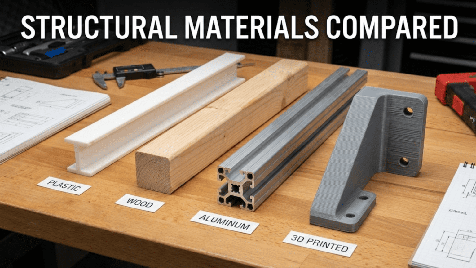
Choosing structural materials for a robot involves balancing four key properties—strength, weight, ease of fabrication, and cost—across the four most common options: wood (cheap, easy to cut, moderate strength, absorbs moisture), plastic sheet and acrylic (lightweight, machinable, brittle under impact), aluminum (strong, lightweight, dimensionally stable, requires more tooling), and 3D printed parts (maximum design freedom, accessible, but anisotropic strength and limited load capacity). The right choice depends on the specific mechanical demands of each robot component, the tools available, the project budget, and whether the design is a one-time prototype or a repeatable production build.
Introduction
You’ve designed your robot on paper. The geometry looks right, the electronics are selected, and the code is taking shape. Now you face a question that every robot builder encounters and that no tutorial seems to address directly: what should the actual physical structure be made of?
Walk into a makerspace and you’ll see robots built from laser-cut plywood, acrylic sheets cut on CNC routers, 3D-printed PLA frames, welded steel tubes, aluminum extrusions, bent sheet metal, carbon fiber plates, and combinations of all of these. Professional industrial robots are built from cast and machined aluminum alloys with hardened steel at the joints. Hobbyist sumo wrestling robots are machined from solid aluminum blocks. Educational robots are laser-cut from plywood. Competition line-followers are 3D printed in lightweight PLA. Commercial delivery robots use carbon fiber composite frames.
Each of these choices was made for specific reasons that connect directly to the mechanical requirements of the application. Understanding those reasons—and the properties that drive them—will let you make confident, informed material choices for your own robots rather than defaulting to “whatever I have” or copying what you saw in a YouTube video.
This article gives you the complete picture: the mechanical properties that matter, how each major material category performs against them, how to fabricate with each, and a systematic framework for deciding what to use in every part of your robot.
The Properties That Matter in Structural Materials
Before comparing materials, you need to understand what properties you’re actually comparing. Six mechanical and practical properties determine whether a material is right for a given robot component.
Strength and Stiffness
These two properties are often confused but are distinct and both important.
Strength is the maximum stress a material can withstand before it permanently deforms (yield strength) or fractures (ultimate strength). A material with high strength can carry large loads without breaking or permanently bending.
Stiffness (modulus of elasticity) describes how much a material deflects under load before yielding. A stiff material deflects very little under the same load that causes a flexible material to bend considerably. Stiffness is often more important than strength in robot structures—a robot arm that bends noticeably under its own weight or payload will produce positioning errors that no amount of software correction can fully fix.
You can have high strength with low stiffness (rubber is strong—it returns to shape—but not stiff) or high stiffness with moderate strength (glass is stiff but not particularly strong—it deflects very little but fractures at modest stress). For robot structures, you typically want both: high stiffness to prevent unwanted deflection and adequate strength to avoid failure under worst-case loads.
Strength-to-Weight Ratio (Specific Strength)
For mobile robots—anything that carries its own weight and moves—the absolute strength of the material matters less than the strength divided by the density. A material that is twice as strong but also twice as heavy provides no structural advantage while doubling the weight that motors must accelerate and batteries must power.
Aluminum alloys have excellent specific strength—significantly better than steel by weight. Carbon fiber composites have exceptional specific strength—among the highest of any engineering material. Understanding specific strength explains why aerospace vehicles use aluminum and carbon fiber rather than steel: they provide the necessary structural performance at a fraction of the weight.
Machinability and Fabrication
How difficult is the material to cut, drill, shape, and join with the tools you have available? This is often the most practically important property for hobbyist and student builders, since the most theoretically optimal material is useless if you can’t work it.
Wood can be cut with a hand saw, shaped with sandpaper, and drilled with a basic drill. Acrylic can be laser-cut or scored and snapped. Aluminum requires dedicated cutting tools but is far more machinable than steel. 3D printing requires only a printer file and patience. Carbon fiber requires special cutting tools (it rapidly destroys standard tools) and is difficult to machine safely without proper dust extraction.
Dimensional Stability
Will the material maintain its shape and dimensions over time, through temperature changes, humidity variations, and mechanical loading? This matters more than it might initially seem. A robot chassis that swells slightly in humid weather and causes previously well-aligned components to bind is a frustrating problem. A plastic bracket that creeps (slowly deforms under sustained load) over weeks of operation will eventually cause misalignment in a joint or motor mount.
Aluminum has excellent dimensional stability—it doesn’t absorb moisture, has a low thermal expansion coefficient compared to polymers, and doesn’t creep under normal loads. Wood is notoriously unstable—it expands and contracts with humidity, warps with moisture gradients, and creeps under load. Most engineering plastics fall in between.
Cost
Material cost directly determines project feasibility for many builders. Wood and PLA filament are among the cheapest structural materials. Aluminum sheet and bar stock are moderately priced and widely available. Carbon fiber is expensive. Titanium is extremely expensive. For one-off student and hobbyist projects, cost often constrains choices more than mechanical performance.
Repairability and Iterability
How easy is it to modify a design that doesn’t work, replace a broken component, or make incremental improvements? For early-stage robotics projects—where the design will almost certainly change multiple times—repairability is enormously valuable. A design that can be rebuilt from scratch in three hours beats a theoretically superior design that takes three days to fabricate.
Material 1: Wood and Plywood
Wood is one of the oldest engineering materials in existence and, perhaps surprisingly, remains genuinely useful in robotics—particularly for prototyping and educational applications.
Properties
Wood’s mechanical properties vary enormously depending on species and grain direction. Plywood—layers of wood veneer with alternating grain directions—is more dimensionally stable and consistently strong than solid wood, and it’s the form most commonly used in robotics applications.
Baltic birch plywood is the preferred choice for laser-cut robot structures. It’s dense, consistent, cuts cleanly on laser cutters, has minimal voids in the core layers, and provides reasonable strength-to-weight ratio. A 6mm sheet of quality birch ply can support tens of kilograms when properly supported—more than enough for most small robot frames.
Tensile strength: Moderate (approximately 40–70 MPa along grain for birch ply) Stiffness: Moderate but acceptable for small robots (8–12 GPa) Density: Light (approximately 600–700 kg/m³) Moisture sensitivity: High — significant weakness for robotics use
Fabrication
Wood’s greatest advantage is fabrication accessibility. Laser cutters can cut intricate wooden robot parts with excellent precision and repeatability. A laser-cut plywood chassis designed in software can go from digital file to finished part in minutes, with every hole, slot, and contour cut precisely.
Without a laser cutter, wood can still be shaped with hand tools: saw, drill, sandpaper, chisel. This makes it accessible to builders with minimal equipment and budget.
Joint design is important for wood structures. Wood doesn’t hold screws as reliably as metal, especially near edges where screw pullout can split the material. Slot-and-tab joints (where laser-cut tabs interlock with slots in the mating piece) create strong, glue-optional connections that are a hallmark of laser-cut plywood robot design:
Designing slot-and-tab joints for laser-cut plywood:

Material thickness: 6mm
Tab width: 10mm (2x material thickness recommended)
Tab height: 5.5mm (slightly less than material thickness for fit)
Kerf compensation: 0.1mm offset for tight fit on most laser cutters

Tip: Design tabs 0.1-0.2mm wider than the slot
for a friction fit that holds without glue during assembly.
Use glue for final assembly once dimensions are verified.When Wood Works Well
Educational and workshop robots: When the goal is learning robotics concepts rather than building an optimized machine, wood is cheap, forgiving, easy to modify, and available everywhere.
Rapid prototyping: When you need to quickly validate a mechanical concept before committing to a more expensive material, laser-cut plywood lets you iterate in hours.
Static or low-vibration applications: Robot arms that move slowly, cart-style robots, and display robots that don’t experience shock loading can use wood effectively.
Very large, lightly loaded structures: For a large flat robot chassis that doesn’t need to be lightweight, a sheet of plywood is extremely cost-effective.
Where Wood Falls Short
High vibration and shock loads: Screws work loose in wood under vibration. Impact loads can split wood along the grain.
Outdoor or humid environments: Wood absorbs moisture, swells, warps, and eventually rots. An outdoor robot with a wooden chassis will gradually become structurally unreliable.
High precision requirement: Wood dimensional stability is insufficient for precise mechanical systems where alignment must be maintained over weeks and months.
Weight-critical designs: For flying robots, fast ground vehicles, or any robot where minimizing mass is critical, wood’s density relative to aluminum or CFRP is a disadvantage.
Material 2: Acrylic and Polycarbonate Sheet Plastics
Laser-cuttable plastic sheets are extremely popular in robot construction due to their combination of accessibility, aesthetics, and reasonable mechanical properties.
Acrylic (PMMA)
Acrylic (Polymethylmethacrylate, also sold as Plexiglas or Perspex) is the most common plastic sheet for laser-cut robot construction. It cuts cleanly on CO₂ laser cutters, leaving smooth edges, and comes in many colors and thicknesses.
Advantages: Excellent laser cuttability, good dimensional stability, not affected by humidity, aesthetically clean appearance, moderate strength, easy to bond with acrylic cement.
Critical weakness: Acrylic is brittle. Under impact loading—a robot falling, a collision, a drive wheel hitting a step—acrylic cracks catastrophically. It has low impact resistance and virtually no ductility, meaning it absorbs very little energy before fracturing. This brittleness is acrylic’s most significant limitation in robotics: a robot that tips over on a hard floor can completely shatter its acrylic chassis.
Polycarbonate (PC)
Polycarbonate has similar stiffness to acrylic but dramatically better impact resistance—it’s the material used in safety glasses, bulletproof glass, and riot shields. It can absorb large impacts without fracturing, deflecting elastically instead.
Advantages over acrylic: Far superior impact resistance, greater ductility, better long-term durability in applications with shock loading.
Disadvantages versus acrylic: More expensive, doesn’t cut as cleanly on laser cutters (more melting and char at cut edges), more difficult to achieve clean cosmetic results without post-processing.
For robots that might experience impacts—competition robots, outdoor explorers, anything a student might drop repeatedly—polycarbonate is worth the extra cost and fabrication effort compared to acrylic.
Fabrication
Both materials can be laser-cut with precision. Acrylic can also be scored and snapped cleanly along straight lines, making it workable without laser equipment. Drilling is straightforward with standard bits, though slow feeds prevent cracking near holes. Bending is possible using a heat strip bender, allowing three-dimensional forms from flat sheet stock.
Joint design for plastic sheet structures uses similar slot-and-tab geometry as wood, or through-bolted connections using M3/M4 hardware. Unlike wood, plastic threads hold screws more reliably, and tapped holes in thicker stock (6mm+) can be used directly without inserts.
When Plastics Work Well
Lightweight chassis for small robots: Acrylic and polycarbonate are lighter than aluminum for equivalent sheet thickness, making them suitable for small wheeled robots where weight matters.
Electrically insulating structures: Plastic is non-conductive. When a chassis needs to be electrically isolated from components—particularly useful for electronics mounting plates where shorts would be catastrophic—plastic provides inherent insulation that aluminum does not.
Budget-conscious builds: Plastic sheet is generally less expensive than aluminum, and laser cutting is widely available at makerspaces and schools.
Robots with primarily bending loads: Well-designed plastic structures resist bending loads adequately for small robots, where the primary structural demands are resisting chassis flex rather than impact.
Material 3: Aluminum
Aluminum is the standard structural material of serious robotics, used everywhere from student competition robots to professional industrial arms. Understanding why requires looking at its properties in combination.
Why Aluminum Dominates Serious Robotics
Aluminum alloys combine four properties in a way no common cheaper material matches: they are strong (yield strength 200–500 MPa depending on alloy and temper), stiff (modulus ~70 GPa), light (density ~2700 kg/m³—about one-third of steel), and dimensionally stable (low thermal expansion, no moisture sensitivity, no creep under normal loads).
The comparison with steel is illuminating: aluminum is one-third the density of steel, but aluminum alloys can approach one-third to one-half the strength of structural steels. For equal load-carrying capacity, aluminum components end up approximately the same weight as steel components while having two to three times the volume—meaning aluminum structures feel “bulky” compared to steel structures of equal strength, but they weigh the same or less. For robot structures where weight, not volume, is the constraint, aluminum is typically the better choice.
The comparison with engineering plastics: aluminum is stiffer and stronger per unit weight than most common engineering plastics, more dimensionally stable, and unaffected by humidity, UV radiation, and most chemicals that degrade plastics over time.
Common Aluminum Forms in Robotics
Aluminum sheet and plate: Flat stock ranging from thin shim (0.5mm) to thick plate (10mm+). Cut with circular saw (carbide blade), jigsaw (metal blade), laser cutter, or CNC router. Used for chassis panels, mounting plates, motor brackets.
Aluminum bar and angle stock: Rectangular bars, square tubing, angle section, and channel. Cut with hacksaw, band saw, or miter saw with carbide blade. Used for frame members, levers, arm links.
Aluminum extrusion (T-slot / 80/20 / MakerBeam): Extruded aluminum profiles with continuous T-slots along their length that accept sliding nuts and bolts. No welding or drilling required for most connections—components are clamped into the slots with T-slot nuts and bolts. T-slot extrusion has become the standard framing system for prototype and lab robots:
T-slot extrusion assembly example:
- 2020 profile: 20mm × 20mm cross section, very light, suitable for small robots
- 3030 profile: 30mm × 30mm, good for medium robots and printer frames
- 4040 profile: 40mm × 40mm, heavy-duty framing for large robot arms

Connections use:
- M5 T-slot nuts + M5 bolts (standard for 2020 profile)
- Corner brackets for 90° joints
- Gusset plates for high-stress connections
- L-brackets for perpendicular connectionsMachined aluminum: Components designed in CAD and machined on a milling machine or CNC router from aluminum bar or plate stock. This is how precision robot arm links, joint plates, and motor mounts are produced professionally. CNC-machined aluminum achieves excellent dimensional accuracy (±0.1mm or better with good setup) and any desired geometry.
Fabrication Considerations
Aluminum is genuinely machinable with modest equipment. A cordless drill, hacksaw, and set of files can produce functional aluminum parts. A drill press dramatically improves hole quality and safety. A band saw or miter saw with a non-ferrous metal blade cuts aluminum quickly and cleanly.
For more complex shapes, a CNC router with carbide end mills cuts aluminum well at appropriate feeds and speeds. Laser cutting aluminum requires fiber laser systems (CO₂ lasers don’t cut aluminum well), which are less commonly available at makerspaces than CO₂ lasers used for wood and acrylic.
Aluminum can be fastened with machine screws into tapped holes (M3 threads hold well in 5mm+ stock), through-bolted with nuts, riveted, or welded (TIG welding aluminum is a specialized skill but produces excellent structural joints).
When Aluminum Is the Right Choice
Precision mechanisms: Any application requiring tight dimensional tolerances maintained over time—motor mounts, bearing housings, gearbox cases, robot joint structures.
Load-bearing structures: Arms, frames, and chassis components that carry significant loads, particularly where deflection must be minimized.
High-vibration environments: Motors and drive systems create vibration. Aluminum structures maintain their fastened connections better than wood under continuous vibration.
Long-term reliability: A robot expected to operate for months or years without structural issues benefits from aluminum’s dimensional stability and durability.
Competition robots: Most serious robot competitions (FIRST Robotics, VEX, MATE ROV) see aluminum as the standard construction material because performance matters more than fabrication speed.
Material 4: 3D Printed Parts
3D printing has transformed accessible robotics by enabling the fabrication of complex three-dimensional geometries without any conventional machining equipment. Understanding both its remarkable capabilities and its significant limitations is essential for using it effectively.
The 3D Printing Advantage: Geometric Freedom
The defining advantage of 3D printing is geometric freedom—the ability to produce parts with internal channels, complex curvatures, integrated features, and any shape that can be designed in CAD, without any toolpath limitations or setup costs. This freedom enables designs that would be impossible or prohibitively expensive with conventional manufacturing:
- Internal cable routing channels through arm links
- Integrated motor mount bosses, bearing seats, and wire management features in a single printed part
- Organic, optimized shapes following stress paths rather than being constrained to simple rectangular forms
- Custom interface geometries for mounting non-standard sensors, cameras, and electronics
Common 3D Printing Materials for Robotics
PLA (Polylactic Acid): The most common FDM filament. Easy to print, stiff, decent surface quality, low cost. Major weaknesses: brittle (low impact resistance), poor heat resistance (softens above ~60°C—problematic near motors), degrades slowly outdoors. Best for: light-duty structural parts, prototypes, aesthetic components, non-load-bearing housings.
PETG (Polyethylene Terephthalate Glycol): Tougher than PLA, better heat resistance (~80°C), less brittle, slightly flexible. More difficult to print than PLA (stringing, adhesion issues). Best for: parts that need more impact resistance than PLA, outdoor components, food-safe applications.
ABS (Acrylonitrile Butadiene Styrene): Older standard for FDM. Better heat resistance than PLA (~100°C), more impact resistant, easier to post-process (acetone smoothing). Difficult to print (warping, fumes, requires enclosure). Largely replaced by PETG for most applications.
TPU (Thermoplastic Polyurethane): Flexible, rubber-like material. Used for wheels, grippers, vibration-damping mounts, and flexible robot links. Prints slowly; requires tuning.
Nylon: High toughness, excellent fatigue resistance, good heat resistance, low friction (useful for bushings and gears). Absorbs moisture (must be dried before and during printing), difficult to print well without enclosure.
Carbon fiber-filled filaments (PLA-CF, PETG-CF, Nylon-CF): Base polymer reinforced with chopped carbon fiber. Significantly stiffer and lighter than unfilled equivalents. More brittle than unfilled versions, abrasive to standard brass nozzles (requires hardened steel nozzle). Good for lightweight, stiff structural parts where impact resistance is secondary.
The Critical Weakness: Anisotropic Strength
FDM 3D printing builds parts layer by layer. This process creates a material that is significantly weaker in one direction than others—specifically, much weaker in the direction perpendicular to the layers (the Z-axis, along the build direction) than in the plane of the layers.
A 3D-printed part loaded along the Z-axis will delaminate (layers separate) at stresses far below those that would fracture the same part loaded in the X-Y plane. This anisotropy must be considered during part orientation for printing:
Part orientation strategy for maximum strength:

For a robot arm bracket with bolt holes:
- Orient so the highest-stress direction aligns with X-Y (layer plane)
- Bolt holes loaded in tension: orient so the tensile load
  direction is IN the layer plane, not pulling layers apart
- If the part must resist bending: orient so bending stress
  loads layers in shear (within the plane) not tension (between layers)

Common mistake: printing flat (Z-axis = thin dimension)
creates maximum area per layer but puts all bolt-tensile stress
across layer boundaries — exactly the weakest direction.
Better: print the part upright so bolt holes are printed round,
and tensile load is in-plane.Design Practices for Strong 3D Printed Robot Parts
Several design practices maximize the structural performance of 3D-printed robot components:
Increase infill percentage for load-bearing parts: Standard cosmetic parts use 15–20% infill. Structural robot parts should use 40–80% infill. Load-critical parts can use 100% infill, though this increases print time and weight.
Increase perimeter count: More outer perimeter passes (walls) dramatically increase strength in the X-Y plane and improve hole quality. 4–6 perimeters instead of the default 2–3 makes a significant difference for structural parts.
Add fillets to internal corners: Sharp internal corners concentrate stress and initiate cracks. Adding fillets (rounded transitions) of at least 1–2mm radius at all internal corners greatly improves fatigue life.
Use metal inserts for threaded connections: Standard screws threaded directly into plastic loosen over time and strip easily. Brass heat-set inserts pressed into printed holes with a soldering iron create metal threads that hold screws reliably through many assembly cycles:
Heat-set insert installation:
- Design hole diameter = insert OD - 0.3mm for tight press fit
- Set soldering iron to 200-230°C (for PLA)
- Press insert into hole with iron tip
- Insert pulls itself in as plastic softens
- Remove iron, allow to cool undisturbed 60 seconds
- Result: metal thread that outlasts the printed partAdd reinforcement for bolt holes: Print extra material around bolt holes, or design metal washer pockets. The area around through-holes is a common failure point in printed structures.
When 3D Printing Wins
Complex custom geometries: When you need a bracket that mounts a specific sensor at a specific angle with integrated cable routing and fits in a tight space—3D print it. No other method produces such a part as quickly or cheaply.
Small production quantities of identical parts: Printing five identical motor mounts is as easy as printing one. For small-run production, 3D printing beats all conventional manufacturing methods on cost.
Rapid iteration: CAD-to-part in hours. Redesign, reprint, test, repeat. No other fabrication method enables this iteration speed for custom 3D geometries.
Organic and optimized shapes: Topology-optimized parts that remove material where stresses are low can be 3D printed directly, reducing weight while maintaining strength.
Grippers and compliant mechanisms: Flexible printed structures (in TPU or even carefully designed PLA) can create compliant grippers that conform to object shapes—designs that are impossible to manufacture conventionally.
Where 3D Printing Falls Short
High-load structural members: A 3D-printed robot arm link carrying significant payload will creep, deflect excessively, or eventually fail at layer boundaries under sustained load. High-load structural members should be aluminum or carbon fiber, not PLA.
Precision bearing housings: Printed holes have tolerances of ±0.2–0.5mm depending on printer quality and material. Bearing fits require ±0.01–0.05mm tolerance. Bearings pressed into printed holes will either be too loose (they fall out) or too tight (they deform the plastic). Use machined aluminum for precision bearing seats.
High-temperature environments: Near motors, under continuous sunlight, or in enclosed spaces, PLA will soften and deform. Use ABS, PETG, Nylon, or ideally aluminum for heat-exposed components.
Impact-loaded parts: Gears in high-torque gearboxes, chassis components that take impacts from collisions or drops, any component subject to shock loading—printed parts fail prematurely. Use aluminum, polycarbonate, or nylon for impact-sensitive applications.
Advanced Materials: Carbon Fiber, Steel, and Composites
While wood, plastics, aluminum, and 3D printing cover the majority of hobbyist and student robotics, advanced builders work with additional materials worth understanding.
Carbon Fiber Reinforced Polymer (CFRP)
Carbon fiber composites offer the highest specific stiffness and strength of any common engineering material—significantly better than aluminum by weight. A carbon fiber plate is dramatically stiffer and lighter than an aluminum plate of equal strength.
When it’s worth using: Lightweight competition robots, drone frames, robot arms where deflection is critical, any application where every gram matters.
Why most builders avoid it: Expensive (5–10x aluminum cost), difficult to machine without special tooling (carbide tools, dust extraction essential—carbon fiber dust is hazardous), cannot be laser-cut, difficult to repair, and requires careful design because CFRP failure is often sudden and brittle rather than gradual and ductile.
For most hobbyist and student robots, the weight and stiffness advantage of carbon fiber doesn’t justify the cost and fabrication difficulty. For competition drones, racing robots, and payload-critical applications, it’s often indispensable.
Steel
Steel is stronger and stiffer than aluminum in absolute terms, but its density is three times higher, making it heavier for equivalent structural performance. Steel is generally avoided in mobile robot structures for this reason, except for applications where:
- Very high load capacity is needed (heavy-lift industrial arms)
- Hardness is required (gears, shafts, bearings)
- Magnetic properties are exploited (electromagnetic grippers, motor cores)
- Cost absolutely dominates (steel angle stock is among the cheapest structural material by weight)
Steel shafts are standard in robotics—the combination of hardness, machinability, and reasonable cost makes them the default for axles, motor output shafts, and precision spindles.
Complete Material Comparison Table
| Property | Plywood | Acrylic | Polycarbonate | Aluminum | PLA Print | PETG Print | CF Composite |
|---|---|---|---|---|---|---|---|
| Tensile Strength | Low–Mod | Moderate | Moderate | High | Low–Mod | Moderate | Very High |
| Stiffness (E) | Low–Mod | Moderate | Moderate | High | Low | Low | Very High |
| Impact Resistance | Moderate | Very Low | Very High | High | Low | Moderate | Low–Mod |
| Density (kg/m³) | 600–700 | 1180 | 1200 | 2700 | 1240 | 1270 | 1500–1600 |
| Moisture Stability | Poor | Excellent | Excellent | Excellent | Good | Good | Excellent |
| Laser Cuttable | Yes ✓ | Yes ✓ | Partial | No ✗ | No ✗ | No ✗ | No ✗ |
| 3D Printable | No ✗ | No ✗ | No ✗ | No ✗ | Yes ✓ | Yes ✓ | Partial |
| CNC Machinable | Yes ✓ | Yes ✓ | Yes ✓ | Yes ✓ | Post-print | Post-print | Difficult |
| Relative Cost | Very Low | Low | Low–Mod | Moderate | Low | Low | High |
| Dimensional Stability | Poor | Good | Good | Excellent | Moderate | Moderate | Excellent |
| Best Robot Application | Prototypes | Light chassis | Impact parts | Precision structures | Custom brackets | Structural housing | Lightweight performance |
A Framework for Material Selection
Rather than prescribing a single “right” material, good material selection follows a decision process tied to the specific demands of each robot component.
Step 1: Define the Load Case
What forces and moments will this component experience? Is it primarily tension, compression, bending, or torsion? Will it experience sustained static loads, dynamic impact loads, vibration, or fatigue? How large are the loads in Newtons or Newton-meters?
For a motor mount bracket: primarily resisting motor reaction torque (torsion and bending). Moderate sustained load, vibration from motor. → Aluminum preferred; printed part acceptable for small motors.
For a robot chassis panel: primarily resisting bending from the weight of mounted components. Static load, occasional impact if robot falls. → Aluminum, polycarbonate, or thick plywood all viable depending on size and precision requirements.
Step 2: Identify Precision Requirements
Does this component need to hold precise dimensions over time? Is it a bearing housing? Does a shaft pass through it? Does its dimensional accuracy affect robot positioning?
Precision bearing housing: Aluminum (machined to tolerance) or commercial bearing blocks. Never 3D printed.
Sensor mount that only needs to be “approximately in the right place”: Any material, 3D printing ideal.
Step 3: Assess Available Fabrication Capability
What tools do you have access to? Laser cutter: wood and acrylic are natural choices. 3D printer: opens up custom geometries. CNC router or milling machine: aluminum and dense plastics. Hand tools only: wood is easiest; aluminum requires patience and care.
Step 4: Consider the Thermal Environment
Is the component near motors or other heat sources? PLA softens at 60°C—unacceptable near high-current motor drivers or brushed motors. PETG handles 80°C. ABS/Nylon handle 100°C. Aluminum tolerates any temperature your robot will experience.
Step 5: Evaluate the Iteration Cycle
Is this a final, refined design or early prototype? Early prototype: 3D printing and laser-cut plywood offer the fastest iteration. Final production: aluminum provides the durability and precision for reliable long-term operation.
Practical Combinations: Using Multiple Materials Effectively
The best robots don’t use a single material—they use each material where it performs best. A common and highly effective combination:
Aluminum extrusion frame (T-slot 2020 or 3030): The structural skeleton. Provides dimensional stability, rigidity, and easy adjustability through the T-slot system.
3D printed brackets and connectors: Custom parts that attach specific components—motors, sensors, wheels, electronics—to the aluminum frame. Geometric freedom allows perfect fit. Loads are kept modest.
Aluminum plates for motor mounts and joint structures: Where precision and rigidity matter most, machined or CNC-cut aluminum maintains alignment.
Polycarbonate for covers and guards: Protects electronics from impact while being transparent enough to see inside for debugging.
TPU printed parts for wheels and contacts: Flexible printed parts provide grip and vibration damping without requiring separate rubber components.
This hybrid approach is how professional robot designers work—using the right material for each component based on its specific demands rather than forcing every part to use the same material for simplicity.
Summary
Material selection in robotics is a multi-variable optimization problem. Wood offers unmatched fabrication accessibility and cost for prototyping but lacks dimensional stability and impact resistance. Acrylic is clean and laser-cuttable but critically brittle under impact. Polycarbonate improves impact resistance substantially at modest additional cost. Aluminum combines strength, stiffness, light weight, and dimensional stability into the most reliable structural material for serious robot structures, at the cost of requiring more capable fabrication tools. 3D printed parts offer geometric freedom and rapid iteration that no other method matches, but their anisotropic strength and limited high-temperature performance restrict them to appropriate applications.
The key insight is that material choice should be made per component, not per robot. The chassis frame, the motor mounts, the sensor brackets, the wheel hubs, and the covers all have different mechanical demands and may be best served by different materials. Building good material judgment means understanding what each material is good at, what it’s bad at, and matching those properties to the specific demands of each part you’re designing.
The next article shifts from materials to wheels—specifically, how to choose the right wheel type for your robot’s mobility requirements, including the trade-offs between different wheel geometries, surface materials, and attachment methods that determine how your robot actually moves through its environment.