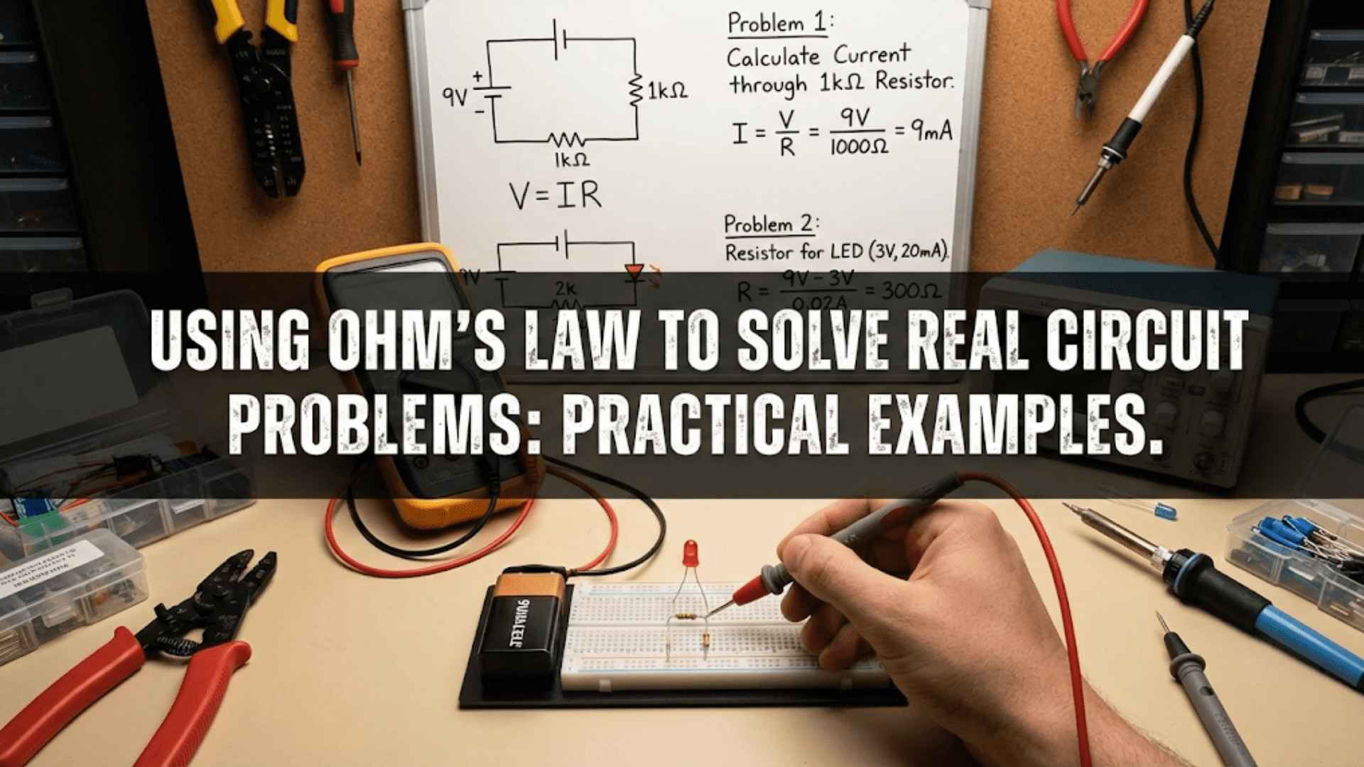
Stepper motors achieve precise positional control without position sensors by dividing one full shaft rotation into a fixed number of discrete steps—typically 200 steps per revolution (1.8° per step)—where each electrical pulse moves the shaft exactly one step and the motor holds that position firmly between pulses, allowing robots to track position simply by counting pulses without any encoder or feedback mechanism. This open-loop precision makes stepper motors the dominant actuator choice for 3D printers, CNC machines, laser cutters, and any application requiring repeatable positioning over moderate distances.
Your 3D printer’s extruder moves precisely 0.1mm per command, depositing filament in exact quantities without any position sensor confirming the movement. Your CNC router’s cutting head travels to within 0.02mm of the programmed coordinates, carving precise features into wood or aluminum. Your telescope mount tracks celestial objects across the sky, advancing at exactly the right angular rate to compensate for Earth’s rotation. None of these systems use encoders to verify position. None use closed-loop feedback to correct errors. They achieve their precision through a fundamentally different mechanism—the discrete, countable steps of stepper motors.
Stepper motors occupy a unique position in the actuator landscape, bridging the simplicity of DC motors and the position awareness of servo systems through an elegant electromagnetic mechanism. Instead of spinning continuously like a DC motor, a stepper motor advances in precise, discrete angular increments called steps. Each electrical pulse produces exactly one step—no more, no less. Count the pulses, and you know the position. Apply a known number of pulses, and you move a known distance. No encoder required, no feedback loop necessary, no calibration complexity—just reliable, repeatable, countable motion.
This article explains stepper motors comprehensively: the electromagnetic mechanism that creates discrete steps, the different winding configurations (unipolar versus bipolar), the step modes that trade off between resolution and torque, the driver ICs that make stepper control practical, complete wiring and programming guides for the most popular drivers, and a clear framework for when stepper motors outperform alternatives. Whether you’re building a 3D printer, a pick-and-place machine, or any precision motion system, this understanding makes you a confident stepper motor user.
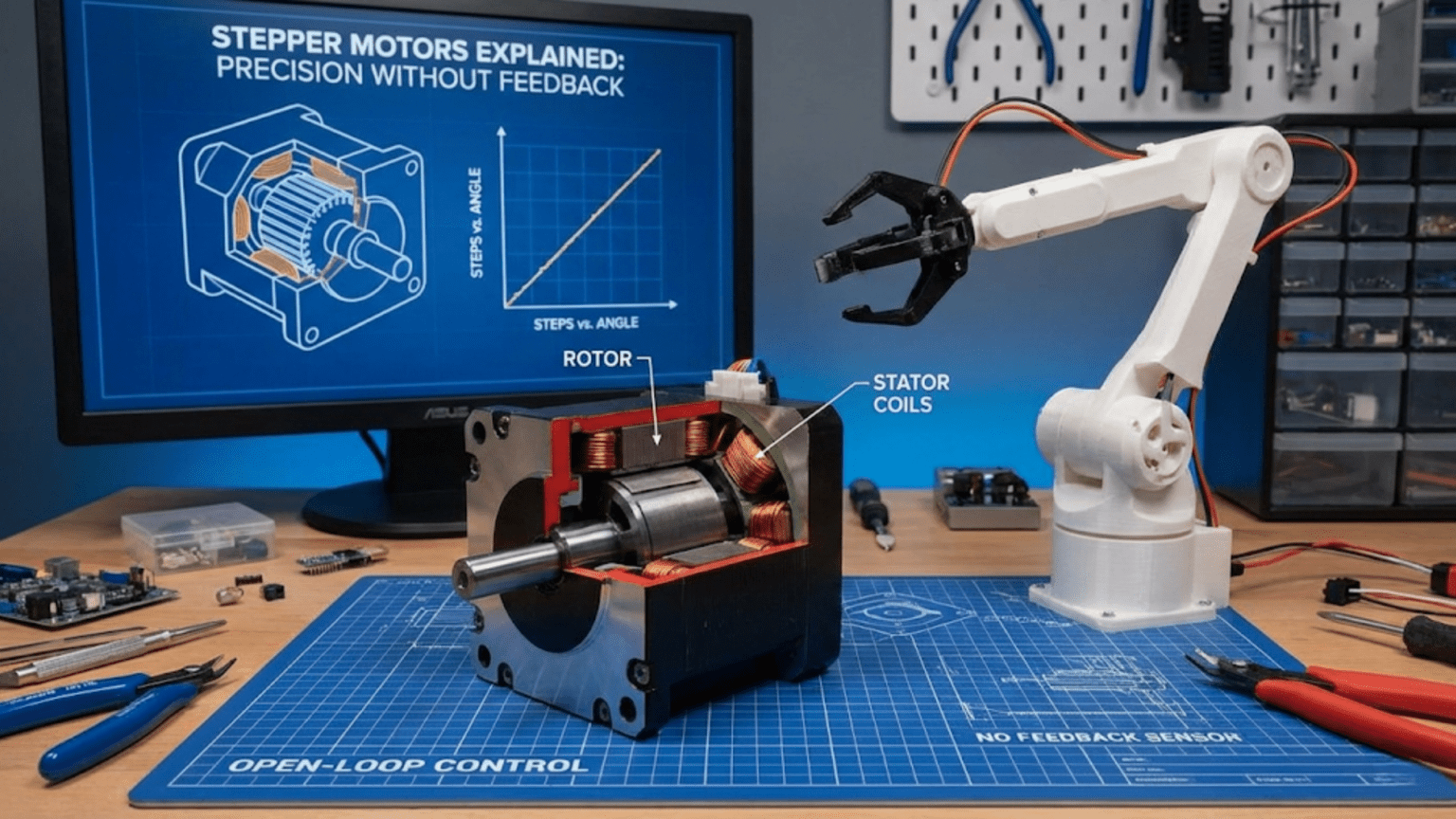
How Stepper Motors Work: The Electromagnetic Mechanism
Stepper motors generate discrete steps through precisely arranged electromagnetic coils and a toothed rotor, creating the defining characteristic that separates them from all other motor types.
The Rotor and Stator Structure
A typical stepper motor contains:
Rotor: A permanent magnet (or soft iron in some designs) with multiple tooth-like poles spaced around its circumference. The rotor is mechanically connected to the output shaft.
Stator: The stationary outer body containing multiple electromagnet coils wound around poles arranged around the inside circumference. These coils, called phases or windings, are energized sequentially by the driver electronics.
The interaction: When a stator coil is energized, it creates a magnetic field that attracts the nearest rotor tooth, pulling the rotor to align with that coil. Energize the next coil in sequence and the next rotor tooth aligns—one step of rotation has occurred. Continue the sequence and the rotor advances one step at a time, each step precisely equal to the last.
The 200 Steps Per Revolution Standard
Most hobby and industrial stepper motors have 200 full steps per revolution, meaning each step rotates the shaft exactly 1.8°:
360° ÷ 200 steps = 1.8° per step
This comes from the internal tooth count:
- Many motors have 50 rotor teeth
- With a 4-phase stator, this produces 50 × 4 = 200 steps per revolution
The 1.8° step angle is the dominant standard, though 0.9° (400 steps/revolution) steppers exist for applications needing finer resolution without microstepping.
The Four-Phase Energization Sequence
For a standard bipolar stepper with two coils (phases), the energization sequence creates the stepping motion:
Full step sequence (one coil at a time, wave drive):
Step  Coil A+  Coil A-  Coil B+  Coil B-
  1     ON       OFF      OFF      OFF    → Rotor aligns to A+
  2     OFF      OFF      ON       OFF    → Rotor aligns to B+
  3     OFF      ON       OFF      OFF    → Rotor aligns to A-
  4     OFF      OFF      OFF      ON     → Rotor aligns to B-
(repeat from Step 1)Each transition advances the rotor one step. The motor “locks” to each position because the energized coil actively holds the rotor against moderate torques—this is holding torque, and it’s what allows steppers to maintain position without braking circuitry.
Full step sequence (two coils at a time, full drive):
Step  Coil A  Coil B
  1    +A      +B    → Rotor aligns between A+ and B+
  2    -A      +B    → Rotor aligns between A- and B+
  3    -A      -B    → Rotor aligns between A- and B-
4 +A -B → Rotor aligns between A+ and B-Energizing both coils simultaneously increases torque (~40% more than single-coil drive) at the cost of higher current consumption.
Holding Torque vs. Running Torque
Holding torque: The torque required to rotate the shaft when coils are energized and the motor is stationary. This is the motor’s rated torque—typically highest when both coils are energized.
Running torque: The torque available while the motor is stepping. Running torque decreases significantly at higher step rates because the coils don’t fully energize before the next step is commanded. At very high speeds, the motor may lose synchronization and miss steps—a phenomenon called step loss that corrupts position tracking.
Detent torque: A small residual torque that exists even with coils de-energized, caused by the permanent magnet’s interaction with the stator teeth. Much lower than holding torque but provides some position retention when unpowered.
Unipolar vs. Bipolar: Two Winding Configurations
Stepper motors come in two fundamental winding configurations that affect driver complexity and performance.
Unipolar Steppers
Unipolar motors have a center tap on each coil winding, creating effectively two separate half-coils per phase:
Coil A:   A1 ──────[center tap]────── A2
Coil B: B1 ──────[center tap]────── B2Wire count: 5 wires (2 per coil + 1 shared center tap) or 6 wires (2 per coil + 2 separate center taps)
Driver simplicity: Current flows from center tap through only half the winding in each step—driver transistors only need to switch current in one direction (simpler, cheaper drivers possible).
Performance trade-off: Using only half the winding at a time means lower inductance per step, but also lower effective torque compared to using the full winding.
Identification: Common unipolar motors include the 28BYJ-48 (the inexpensive 5-wire stepper included in many Arduino kits) with a 5-wire connector.
Bipolar Steppers
Bipolar motors have no center tap—each coil is a single continuous winding:
Coil A:   A1 ──────────────────── A2
Coil B: B1 ──────────────────── B2Wire count: 4 wires (2 per coil)
Driver requirement: Current must flow in both directions through each coil—requires an H-bridge for each coil (effectively two H-bridges total, four transistors per motor). This is more complex but necessary for full winding utilization.
Performance advantage: The full winding is used in every step, providing maximum torque for the motor’s physical size. Bipolar motors produce approximately 40% more torque than equivalent unipolar motors.
Identification: 4-wire steppers are bipolar. NEMA 17 and most larger stepper motors used in 3D printers and CNC machines are bipolar.
Converting Unipolar to Bipolar Operation
6-wire unipolar motors can operate in bipolar mode by simply leaving the center taps unconnected and using the coil ends as a bipolar motor. This provides the full-winding torque advantage while using a more complex driver—a worthwhile trade-off in most applications.
Step Modes: Trading Resolution for Torque
Modern stepper motor drivers support multiple step modes that divide each full step into smaller microsteps, offering flexibility between resolution and torque.
Full Step Mode (1x)
Each driver pulse advances the motor exactly one full step (1.8° for a standard motor).
- Resolution: 200 steps/revolution = 1.8°/step
- Torque: Maximum (both coils fully energized in full drive mode)
- Smoothness: Noticeably coarse motion at low speeds; vibration can be significant
- Use when: Maximum torque is critical; speed is more important than smoothness
Half Step Mode (2x)
The driver alternates between energizing one coil and two coils, creating intermediate positions between full steps.
- Resolution: 400 steps/revolution = 0.9°/step
- Torque: Approximately 70% of full-step torque (lower during single-coil steps)
- Smoothness: Noticeably smoother than full step; still audible at low speeds
- Use when: Balance between torque and resolution is needed
Quarter Step Microstepping (4x)
Current through each coil is modulated in small increments (like sine waves), creating positions between half steps.
- Resolution: 800 steps/revolution = 0.45°/step
- Torque: ~85% of full-step torque
- Smoothness: Much smoother motion; reduced vibration
1/16 Step Microstepping (16x) — Most Common for 3D Printers
The A4988 driver’s most popular mode, dividing each step into 16 microsteps.
- Resolution: 3200 steps/revolution = 0.1125°/step
- Torque: ~70% of full-step torque
- Smoothness: Very smooth motion; 3D printers use this mode for quality prints
- Use when: Smooth motion and good resolution both matter
1/32 Step Microstepping (32x) — DRV8825 Maximum
- Resolution: 6400 steps/revolution = 0.05625°/step
- Torque: ~60% of full-step torque
- Smoothness: Extremely smooth; near-silent at moderate speeds
The microstepping trade-off: Microstepping improves smoothness but doesn’t proportionally improve positional accuracy. The intermediate microstep positions are theoretically defined but practically less reliable than full steps—friction, load variations, and motor non-idealities mean that actual position at a microstep may be slightly different from theoretical. For this reason, 3D printers and CNC machines typically home to full steps and use microstepping primarily for smoothness rather than accuracy.
Rule of thumb: Use microstepping for smooth motion; rely on full steps for position accuracy; verify actual position with sensors for critical applications.
Popular Stepper Motor Drivers
Several driver ICs have become standard in hobby and maker robotics. Understanding each helps you choose appropriately.
A4988: The Ubiquitous Standard
The Allegro A4988 bipolar stepper driver dominates the 3D printing and maker communities due to its excellent feature set at low cost.
Specifications:
- Motor voltage: 8-35V
- Maximum current: 2A per coil (with heat sinking)
- Step modes: Full, 1/2, 1/4, 1/8, 1/16
- Logic voltage: 3.3V or 5V compatible
- Built-in current limiting (set via potentiometer)
- Overcurrent and thermal protection
- Cost: $1-4 per module
A4988 Pin Layout:
A4988 Module Pins:
VMOT   — Motor power supply (8-35V)
GND    — Power ground (motor side)
2B,2A  — Coil B connections (motor)
1A,1B  — Coil A connections (motor)
VDD    — Logic power (3.3-5V from Arduino)
GND    — Logic ground (connect to Arduino GND)
RESET  — Active low reset (tie to SLEEP or 5V)
SLEEP  — Active low sleep mode (tie to RESET or 5V for always active)
STEP   — One pulse = one step
DIR    — Direction (HIGH or LOW)
MS1    — Microstepping select bit 1
MS2    — Microstepping select bit 2
MS3    — Microstepping select bit 3
ENABLE — Active low enable (leave disconnected or tie to GND to enable)
Microstepping mode selection (MS1, MS2, MS3):
| MS1 | MS2 | MS3 | Mode |
|---|---|---|---|
| LOW | LOW | LOW | Full step |
| HIGH | LOW | LOW | Half step |
| LOW | HIGH | LOW | Quarter step |
| HIGH | HIGH | LOW | Eighth step |
| HIGH | HIGH | HIGH | Sixteenth step |
Wiring A4988 to Arduino:
A4988           Arduino/Power
VMOT    →       Motor power supply (12V typical)
GND(motor) →    Motor power supply GND
VDD     →       Arduino 5V
GND(logic) →    Arduino GND
STEP    →       Arduino digital pin (e.g., Pin 3)
DIR     →       Arduino digital pin (e.g., Pin 4)
RESET   →       Arduino 5V (or connect to SLEEP)
SLEEP   →       Arduino 5V (or connect to RESET)
MS1/MS2/MS3 →   Set mode (tie to GND or 5V per table above)
ENABLE  →       Leave disconnected (internally pulled low = enabled)

Coil A (1A,1B) → Motor coil A wires
Coil B (2A,2B) → Motor coil B wiresCRITICAL: Decoupling capacitor! Add a 100µF capacitor between VMOT and GND as close to the A4988 as possible. Without this, voltage spikes when the motor changes direction can permanently destroy the A4988 chip—this is the single most common cause of A4988 failures.
Setting current limit: The A4988 has a potentiometer for current limiting. Set it correctly to avoid overheating motors and drivers:
Current Limit = VREF × 2.5
→ VREF = Motor rated current ÷ 2.5

Example: Motor rated at 1.0A
→ VREF = 1.0A ÷ 2.5 = 0.4V
→ Measure VREF at the potentiometer wiper pin while adjustingDRV8825: Higher Current and More Microsteps
Texas Instruments’ DRV8825 is pin-compatible with the A4988 but offers higher current capability and finer microstepping.
Improvements over A4988:
- Motor voltage: 8.2-45V (higher voltage capability)
- Maximum current: 2.5A per coil (45% more than A4988)
- Step modes: Full, 1/2, 1/4, 1/8, 1/16, 1/32 (finer than A4988)
- Better thermal performance
- Current limit formula: Current = VREF × 2.0 (different from A4988)
When to choose DRV8825 over A4988:
- Motors rated above 1.5A per coil
- Higher voltage motor supplies (above 35V)
- Applications needing 1/32 microstepping for ultra-smooth motion
Wiring: Identical to A4988 (pin-compatible); same 100µF capacitor requirement applies.
TMC2208/TMC2209: The Silent Steppers
Trinamic’s TMC series drivers represent a significant advancement in stepper control, particularly their StealthChop technology which makes motors nearly silent.
Key features:
- StealthChop2: Nearly silent operation at low-to-medium speeds
- SpreadCycle: High-performance mode for faster motion
- stallGuard4 (TMC2209): Sensorless homing using back-EMF detection
- UART interface for software configuration
- Current: Up to 1.2A RMS (TMC2208) or 1.4A RMS (TMC2209) continuous
- Pin-compatible with A4988/DRV8825 in basic mode
Why silent steppers matter: Standard A4988/DRV8825 drivers at high microstepping rates produce a distinctive high-pitched whine from the chopper frequency. TMC drivers’ StealthChop virtually eliminates this noise—critical for desktop 3D printers, laboratory instruments, and any noise-sensitive environment.
Simple use (analog mode, A4988-compatible):
// TMC2208/2209 in standalone mode - wire identically to A4988
// Just plug in place of A4988 for silent operation
// Configure microstepping via physical pins (same as A4988)Programming Stepper Motors: From Basics to AccelStepper
Basic Stepper Control Without a Library
Understanding the fundamental pulse sequence helps before using higher-level libraries:
// Basic A4988 stepper control - no library required

const int stepPin = 3;
const int dirPin = 4;

void setup() {
  pinMode(stepPin, OUTPUT);
  pinMode(dirPin, OUTPUT);
  Serial.begin(9600);
}

// Move stepper a specific number of steps
// steps: positive = forward, negative = backward
// delayMicros: pulse delay (smaller = faster)
void moveSteps(long steps, int delayMicros) {
  // Set direction
  if (steps > 0) {
    digitalWrite(dirPin, HIGH);
  } else {
    digitalWrite(dirPin, LOW);
    steps = -steps;  // Make positive for loop
  }

  // Generate step pulses
  for (long i = 0; i < steps; i++) {
    digitalWrite(stepPin, HIGH);
    delayMicroseconds(delayMicros);
    digitalWrite(stepPin, LOW);
    delayMicroseconds(delayMicros);
  }
}

void loop() {
  Serial.println("Forward 200 steps (1 revolution)");
  moveSteps(200, 1000);   // 200 steps at 1ms per pulse
  delay(1000);

  Serial.println("Reverse 400 steps (2 revolutions)");
  moveSteps(-400, 1000);
  delay(1000);

  Serial.println("Fast forward 1000 steps");
  moveSteps(1000, 200);   // Much faster (200µs delay)
  delay(1000);
}Calculating speed from delay:
- Step frequency = 1,000,000 µs ÷ (2 × delay_microseconds)
- RPM = (Step frequency ÷ steps_per_revolution) × 60
- Example: 1000µs delay → 500 Hz → 500÷200×60 = 150 RPM
- Example: 200µs delay → 2500 Hz → 2500÷200×60 = 750 RPM
AccelStepper Library: The Professional Solution
The AccelStepper library adds essential features: smooth acceleration, deceleration, simultaneous multi-motor control, and non-blocking operation.
Install: Arduino IDE → Sketch → Include Library → Manage Libraries → search “AccelStepper”
#include <AccelStepper.h>

// Define motor interface type and pins
// DRIVER means we're using a step/dir driver like A4988
const int stepPin = 3;
const int dirPin = 4;

AccelStepper stepper(AccelStepper::DRIVER, stepPin, dirPin);

void setup() {
  // Set maximum speed (steps per second)
  stepper.setMaxSpeed(1000);

  // Set acceleration (steps per second per second)
  stepper.setAcceleration(500);

  // Set initial speed (for constant speed mode)
  stepper.setSpeed(200);

  Serial.begin(9600);
  Serial.println("AccelStepper initialized");
}

void loop() {
  // Move to absolute position (in steps from start)
  Serial.println("Moving to position 1000");
  stepper.moveTo(1000);

  // Run motor until it reaches position
  // run() returns true while still moving
  while (stepper.distanceToGo() != 0) {
    stepper.run();  // Must be called frequently!
  }
  delay(500);

  Serial.println("Moving to position -500");
  stepper.moveTo(-500);
  while (stepper.distanceToGo() != 0) {
    stepper.run();
  }
  delay(500);

  Serial.println("Moving to position 0 (home)");
  stepper.moveTo(0);
  while (stepper.distanceToGo() != 0) {
    stepper.run();
  }
  delay(1000);
}Non-Blocking Stepper Control
For robots that need to do other things while motors move, use a non-blocking approach:
#include <AccelStepper.h>

AccelStepper stepper(AccelStepper::DRIVER, 3, 4);

// Other sensors/outputs
const int ledPin = 13;
const int sensorPin = A0;

void setup() {
  stepper.setMaxSpeed(800);
  stepper.setAcceleration(400);
  pinMode(ledPin, OUTPUT);
  Serial.begin(9600);
}

void loop() {
  // ===== Motor Control (non-blocking) =====
  stepper.run();  // Call every loop iteration - handles stepping

  // Set new target when motor reaches goal
  if (stepper.distanceToGo() == 0) {
    // Oscillate between two positions
    static bool atFarEnd = false;
    if (atFarEnd) {
      stepper.moveTo(0);
    } else {
      stepper.moveTo(1600);  // 8 revolutions at 200 steps
    }
    atFarEnd = !atFarEnd;
  }

  // ===== Other Robot Tasks (running simultaneously) =====
  // Read sensor
  int sensorValue = analogRead(sensorPin);

  // Update LED based on motor position
  long position = stepper.currentPosition();
  digitalWrite(ledPin, (position % 200 < 100) ? HIGH : LOW);

  // Print status occasionally
  static unsigned long lastPrint = 0;
  if (millis() - lastPrint > 500) {
    Serial.print("Position: ");
    Serial.print(stepper.currentPosition());
    Serial.print(", Target: ");
    Serial.print(stepper.targetPosition());
    Serial.print(", Sensor: ");
    Serial.println(sensorValue);
    lastPrint = millis();
  }

  // Note: NO delay() here - that would block motor stepping!
}Multi-Motor Control with MultiStepper
For synchronized multi-axis motion (like CNC or robot arms):
#include <AccelStepper.h>
#include <MultiStepper.h>

// Two stepper motors for XY table
AccelStepper stepperX(AccelStepper::DRIVER, 3, 4);
AccelStepper stepperY(AccelStepper::DRIVER, 6, 7);

MultiStepper xyTable;

void setup() {
  stepperX.setMaxSpeed(500);
  stepperY.setMaxSpeed(500);

  // Add motors to group
  xyTable.addStepper(stepperX);
  xyTable.addStepper(stepperY);

  Serial.begin(9600);
}

void moveTo(long x, long y) {
  long positions[2];
  positions[0] = x;
  positions[1] = y;

  // MultiStepper automatically coordinates speeds
  // so both motors finish simultaneously
  xyTable.moveTo(positions);
  xyTable.runSpeedToPosition();  // Blocks until complete

  Serial.print("Moved to X:");
  Serial.print(x);
  Serial.print(" Y:");
  Serial.println(y);
}

void loop() {
  // Move to corners of a square
  moveTo(1000, 0);
  moveTo(1000, 1000);
  moveTo(0, 1000);
  moveTo(0, 0);
}Complete Practical Example: Linear Axis with Homing
A complete linear positioning system with limit switch homing—the core of 3D printers and CNC machines:
#include <AccelStepper.h>

// Stepper motor
const int stepPin = 3;
const int dirPin = 4;
AccelStepper axis(AccelStepper::DRIVER, stepPin, dirPin);

// Limit switch at home position
const int homeSwitchPin = 2;

// Axis parameters
const int STEPS_PER_MM = 80;     // Steps to move 1mm (depends on leadscrew pitch and microstepping)
                                  // Example: 1/16 microstepping, 200steps/rev, 2.5mm pitch leadscrew
                                  // = (200 × 16) ÷ 2.5 = 1280 steps/mm... adjust for your hardware
const long MAX_POSITION_MM = 200; // Physical travel limit in mm

float currentPosition_mm = 0;

void setup() {
  axis.setMaxSpeed(3000);         // steps/second
  axis.setAcceleration(2000);     // steps/second²

  pinMode(homeSwitchPin, INPUT_PULLUP);
  Serial.begin(9600);

  Serial.println("Linear Axis Controller");
  Serial.println("Commands: H=home, G[mm]=go to position");
  Serial.println("Example: G50 moves to 50mm");

  // Perform homing on startup
  homeAxis();
}

void homeAxis() {
  Serial.println("Homing...");

  // Phase 1: Move toward home limit switch (negative direction)
  axis.setMaxSpeed(1000);  // Slow approach
  axis.move(-100000);       // Move far enough to definitely hit switch

  while (digitalRead(homeSwitchPin) == HIGH) {
    axis.run();

    // Safety check - if too many steps taken without finding home
    if (abs(axis.distanceToGo()) < 100) {
      Serial.println("ERROR: Home switch not found!");
      axis.stop();
      return;
    }
  }

  // Phase 2: Switch hit - stop immediately
  axis.stop();
  axis.setCurrentPosition(0);
  Serial.println("Switch found - backing off");

  // Phase 3: Back off from switch
  axis.setMaxSpeed(500);
  axis.moveTo(5 * STEPS_PER_MM);  // Back off 5mm
  while (axis.distanceToGo() != 0) {
    axis.run();
  }

  // Phase 4: Slow final approach
  axis.setMaxSpeed(200);          // Very slow final approach
  axis.move(-100000);

  while (digitalRead(homeSwitchPin) == HIGH) {
    axis.run();
  }

  // Home found precisely
  axis.stop();
  axis.setCurrentPosition(0);
  currentPosition_mm = 0;

  // Restore normal speed
  axis.setMaxSpeed(3000);
  Serial.println("Homing complete! Position: 0.00mm");
}

void moveToMM(float target_mm) {
  // Clamp to valid range
  target_mm = constrain(target_mm, 0, MAX_POSITION_MM);

  long targetSteps = (long)(target_mm * STEPS_PER_MM);

  Serial.print("Moving to ");
  Serial.print(target_mm);
  Serial.println("mm");

  axis.moveTo(targetSteps);

  while (axis.distanceToGo() != 0) {
    axis.run();

    // Safety: check limit switch during any motion
    if (digitalRead(homeSwitchPin) == LOW && axis.currentPosition() < 0) {
      axis.stop();
      axis.setCurrentPosition(0);
      Serial.println("Limit switch triggered - stopped");
      return;
    }
  }

  currentPosition_mm = (float)axis.currentPosition() / STEPS_PER_MM;
  Serial.print("Arrived at ");
  Serial.print(currentPosition_mm);
  Serial.println("mm");
}

void loop() {
  // Parse serial commands
  if (Serial.available()) {
    char cmd = Serial.read();

    if (cmd == 'H' || cmd == 'h') {
      homeAxis();
    } else if (cmd == 'G' || cmd == 'g') {
      float target = Serial.parseFloat();
      moveToMM(target);
    }
  }

  // Display current position periodically
  static unsigned long lastDisplay = 0;
  if (millis() - lastDisplay > 2000) {
    Serial.print("Current position: ");
    Serial.print(currentPosition_mm);
    Serial.println("mm");
    lastDisplay = millis();
  }
}The 28BYJ-48: The Beginner’s Stepper Motor
The 28BYJ-48 is the inexpensive 5-wire unipolar stepper included in many Arduino starter kits. Understanding it bridges the gap between theory and your first stepper motor project.
Specifications:
- Type: Unipolar, 5-wire
- Step angle: 5.625° per step (32 steps per raw revolution)
- Gear ratio: 1/64 (approximately 64:1 reduction)
- Effective steps per revolution: 32 × 64 = 2048 steps
- Voltage: 5V (perfect for Arduino)
- Current: ~130mA total (low)
- Torque: Low—suitable for light loads only
- Driver: ULN2003 module (included in kit)
Wiring 28BYJ-48 with ULN2003:
ULN2003 Board    Arduino
IN1       →      Pin 8
IN2       →      Pin 9
IN3       →      Pin 10
IN4       →      Pin 11
VCC       →      5V
GND       →      GND

Motor connector → plug directly into ULN2003 boardControlling 28BYJ-48 with Stepper library:
#include <Stepper.h>

// 2048 steps for full revolution with 28BYJ-48 + ULN2003
const int STEPS_PER_REV = 2048;

// Pin order matters for 28BYJ-48: IN1, IN3, IN2, IN4
Stepper myStepper(STEPS_PER_REV, 8, 10, 9, 11);

void setup() {
  myStepper.setSpeed(10);  // RPM (max ~15 RPM for this motor)
  Serial.begin(9600);
}

void loop() {
  Serial.println("Clockwise 1 revolution");
  myStepper.step(STEPS_PER_REV);
  delay(1000);

  Serial.println("Counter-clockwise 1 revolution");
  myStepper.step(-STEPS_PER_REV);
  delay(1000);

  Serial.println("Half revolution");
  myStepper.step(STEPS_PER_REV / 2);
  delay(1000);
}Limitations of 28BYJ-48:
- Very slow maximum speed (~15 RPM)
- Very low torque (0.3 kg·cm max)
- Blocking control (motor must finish before code continues)
- Not suitable for serious robotics—use NEMA 17 for real projects
Comparison Table: Stepper Motor Drivers
| Driver | Max Voltage | Max Current | Step Modes | Key Feature | Cost | Best For |
|---|---|---|---|---|---|---|
| ULN2003 | 12V | 500mA total | Full, Half | Unipolar only, very simple | $1-2 | 28BYJ-48 beginner projects |
| A4988 | 35V | 2A/coil | 1, 1/2, 1/4, 1/8, 1/16 | Industry standard, affordable | $1-4 | 3D printers, CNC, general |
| DRV8825 | 45V | 2.5A/coil | 1, 1/2, 1/4, 1/8, 1/16, 1/32 | Higher current and voltage | $2-5 | Larger motors, higher voltage |
| TMC2208 | 36V | 1.2A RMS | 1/2-1/256 (UART) | Near-silent StealthChop | $4-8 | Quiet 3D printers, lab equipment |
| TMC2209 | 36V | 1.4A RMS | 1/2-1/256 (UART) | Silent + sensorless homing | $5-10 | Advanced 3D printers, CNC |
| L298N | 35V | 2A/channel | Full, Half | Dual H-bridge, widely available | $3-6 | Basic bipolar, low microstepping |
| TB6600 | 42V | 4.5A/coil | 1-1/32 | High current, external driver | $8-15 | Large NEMA 23/34 motors |
When Stepper Motors Are the Right Choice
Use Stepper Motors When:
Open-loop precision is sufficient. For 3D printing, laser engraving, and many CNC applications, accumulated step counts provide adequate position tracking without encoders—assuming steps aren’t lost.
Holding position without power consumption is valuable. Energized steppers hold position firmly against moderate loads. For robotic mechanisms that spend most of their time stationary (camera sliders, telescope mounts, pick-and-place machines), this holding torque without continuous correction is efficient.
Low-to-medium speed with high torque is needed. Stepper motors produce maximum torque at low speeds—opposite of DC motors. Applications requiring high torque at slow, precise movements are ideal stepper candidates.
Exact step counting replaces encoders. When you can guarantee steps aren’t lost (by limiting speed and acceleration appropriately), the stepper’s inherent step counting eliminates encoder cost and complexity.
Choose a Different Motor When:
High speed is required. Stepper motors lose torque rapidly above a few hundred RPM. For high-speed motion, brushless DC motors with encoders outperform steppers dramatically.
Step loss would be dangerous. If a stepper loses steps under overload, it silently accumulates position error. For safety-critical positioning (surgical robots, heavy load positioning), encoder feedback is essential regardless of actuator type.
Energy efficiency matters at rest. Holding current keeps energized steppers warm even stationary. For battery-powered robots requiring long runtime, servo motors (which only draw power when moving) or properly tuned steppers with current reduction may serve better.
Very high positional accuracy is needed. Mechanical backlash in gearboxes and microstep non-idealities limit practical stepper accuracy. Precision ground ball screws, encoders, and closed-loop servo control achieves better accuracy for demanding applications.
Conclusion: Stepper Motors as the Backbone of Precision Motion
Stepper motors achieve something remarkable: precise, repeatable, countable motion without position sensors, using only the inherent physics of electromagnetic step creation. This open-loop precision—reliable enough for the world’s 3D printers, CNC machines, laser cutters, and pick-and-place systems to depend on daily—makes steppers the dominant actuator for applications where moderate-speed precision matters more than maximum efficiency or top speed.
Understanding stepper motors at the level presented here—the electromagnetic mechanism, unipolar versus bipolar winding differences, the resolution-torque trade-offs of step modes, the capabilities of A4988, DRV8825, and TMC series drivers, and the practical implementation of homing routines and acceleration profiles—gives you the foundation to design and implement stepper-based systems confidently.
The progression from the simple 28BYJ-48 beginner motor through NEMA 17 bipolar motors with A4988 drivers to silent TMC2209-based systems mirrors the progression you might follow as your projects grow in sophistication. Each step increases capability and reduces limitations while requiring deeper understanding to implement correctly. The current limiting adjustment that protects your A4988 and motor, the decoupling capacitor that prevents voltage spike failures, the three-phase homing routine that ensures repeatable positioning—these practical details separate working systems from frustrating ones.
The AccelStepper library’s non-blocking operation enables stepper motors to coexist with sensor reading, communication, and other robot behaviors in a single Arduino sketch—making sophisticated multi-tasking stepper-based robots practical without the complexity of multi-threading or real-time operating systems.
Master stepper motors, and you unlock the actuator technology behind the most widespread precision motion systems in the world. Whether you’re building your first 3D printer, designing a custom CNC machine, creating a precision robot arm, or developing automated scientific instrumentation, stepper motor expertise is an indispensable addition to your robotics toolkit.