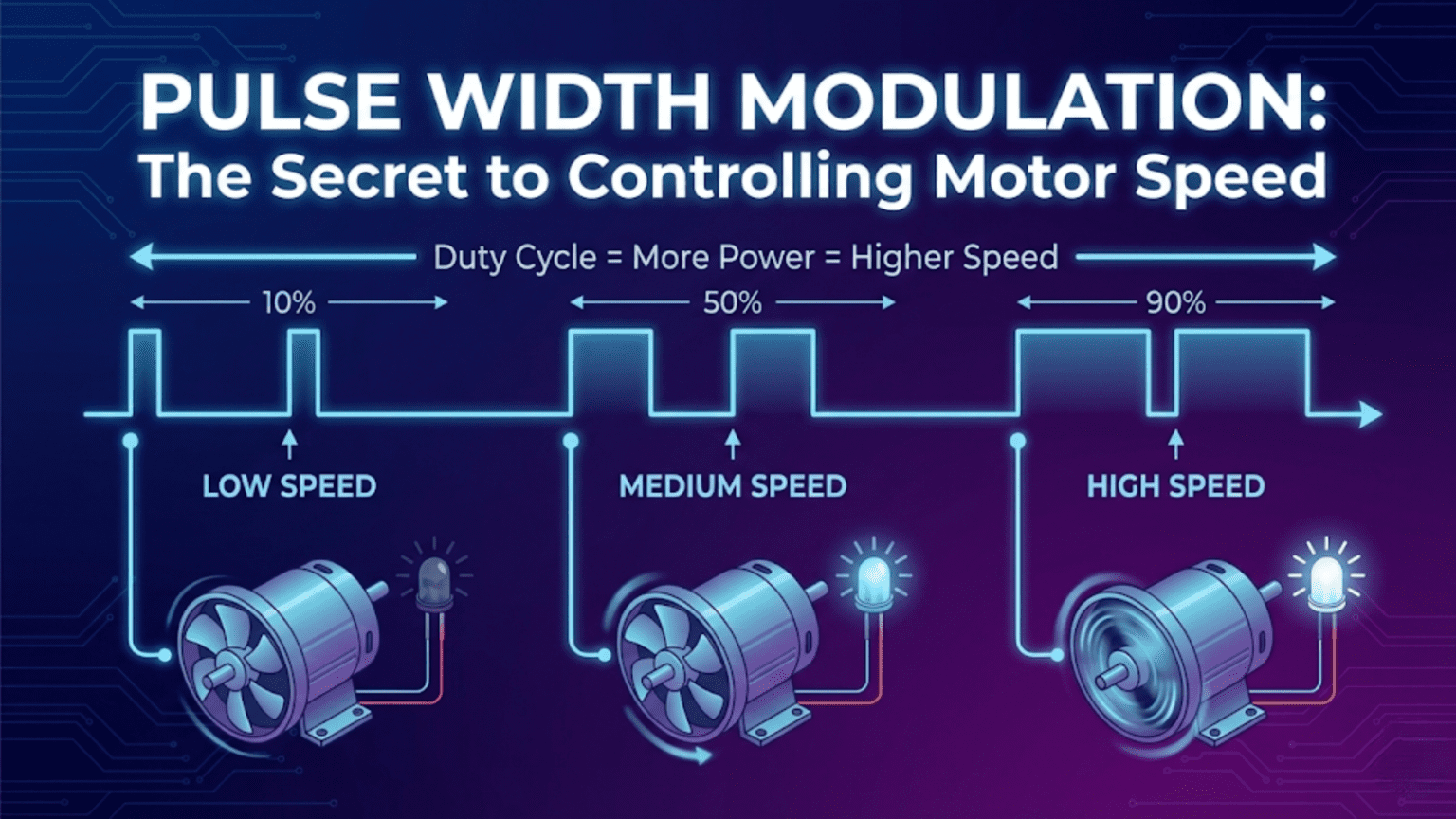
Pulse Width Modulation (PWM) controls motor speed by rapidly switching a digital signal between fully on and fully off at a fixed frequency, with the ratio of on-time to total cycle time—called the duty cycle—determining the effective average voltage delivered to the motor. A 50% duty cycle delivers half the supply voltage on average, running the motor at roughly half speed; 75% duty cycle delivers three-quarters voltage for faster operation; 100% duty cycle (always on) delivers full voltage for maximum speed—making PWM the universal standard for variable-speed motor control in robotics.
You want your robot to move slowly and precisely across a fragile surface, then accelerate smoothly to full speed on open terrain. You need the left motor running 20% faster than the right to compensate for mechanical differences. You want to slow gradually to a stop rather than cutting power abruptly. All of these require variable motor speed—not just full speed or stopped, but any speed in between, changed smoothly and responsively.
The challenge is that digital electronics speak in binary: HIGH or LOW, 5V or 0V, fully on or fully off. Your Arduino cannot output 3.5V by simply commanding it—the pin either outputs 5V or 0V, nothing in between. Yet motors respond to voltage: higher voltage means faster rotation, lower voltage means slower rotation. How do you achieve variable speed with only binary outputs?
The answer—elegant, efficient, and universal—is Pulse Width Modulation. Rather than trying to output a steady intermediate voltage (which would require a digital-to-analog converter), PWM switches the output rapidly between fully on and fully off, varying the ratio of on-time to off-time. Switch on and off fast enough, and the motor’s mechanical inertia effectively averages the pulsed power—the motor spins at a speed corresponding to the average voltage, which is determined entirely by the on/off ratio. This ingenious technique appears in virtually every motor controller, LED dimmer, audio amplifier, and power supply ever built. Understanding PWM thoroughly transforms you from someone who uses analogWrite() without understanding it into someone who can design, implement, and troubleshoot motor control systems with genuine expertise.
The Physics Behind PWM
Understanding why PWM works requires thinking about what motors actually respond to and how averaging occurs physically.
Why Motors Average Pulsed Power
A DC motor spinning at constant speed has mechanical inertia—the rotating mass of its rotor, shaft, and any attached load resists changes in velocity. This inertia acts as a physical low-pass filter. When you pulse power at high frequency, the motor can’t start and stop completely with each pulse—instead, it spins somewhat slower during the off-time and somewhat faster during the on-time, resulting in nearly constant rotation at the speed corresponding to average power.
The key is that the PWM switching frequency must be much higher than the motor’s mechanical time constant—the time it takes the motor to significantly change speed. For most small DC motors used in robotics:
- Mechanical time constant: 50-500 milliseconds
- Arduino default PWM frequency: 490-980 Hz (periods of 1-2 milliseconds)
Because the PWM period (1-2ms) is 25-250 times shorter than the mechanical time constant (50-500ms), the motor effectively sees average power rather than the actual pulsing. The faster the PWM relative to the mechanical response, the smoother the speed control.
Calculating Average Voltage from Duty Cycle
The average voltage delivered to the motor depends linearly on duty cycle:
Average Voltage = Supply Voltage × Duty Cycle
For a 12V supply:
- 0% duty cycle: 0V average (motor stopped)
- 25% duty cycle: 3V average (motor runs slowly)
- 50% duty cycle: 6V average (motor runs at roughly half speed)
- 75% duty cycle: 9V average (motor runs at three-quarters speed)
- 100% duty cycle: 12V average (motor runs at full speed)
Motor speed versus average voltage: Motor speed is approximately proportional to voltage (for simple DC motors under consistent load):
Speed ≈ (Average Voltage / Rated Voltage) × Maximum Speed
For a motor rated at 12V with 1000 RPM maximum:
- At 6V (50% duty cycle): approximately 500 RPM
- At 9V (75% duty cycle): approximately 750 RPM
- At 3V (25% duty cycle): approximately 250 RPM
Important caveat: Motors have a minimum voltage needed to overcome internal friction and start spinning—below this threshold (typically 10-30% duty cycle), the motor receives power but doesn’t rotate. This “dead zone” at low duty cycles must be accounted for in motor control code.
PWM Frequency and Its Effects
PWM frequency—how many complete on/off cycles occur per second—significantly affects performance:
Too low frequency (below ~100 Hz):
- Motor visibly stutters (mechanical response can follow the pulsing)
- Audible buzzing or clicking from motor coils
- Reduced efficiency (motor partially stops and starts)
- LED lights visibly flicker
Optimal frequency (490 Hz – 20 kHz):
- Motor sees smooth average power
- Efficient power delivery
- Minimal audible noise from motor
- Good compromise between switching losses and smoothness
Very high frequency (above 20 kHz):
- Above human hearing (ultrasonic—silent operation)
- Increased switching losses in transistors and drivers
- Faster transistor switching required
- Can reduce motor efficiency due to eddy currents
Arduino default PWM frequencies:
- Pins 5, 6: ~980 Hz
- Pins 3, 9, 10, 11: ~490 Hz
These defaults work well for motor control. Some advanced applications change these frequencies using timer register manipulation.
PWM in Arduino: Using analogWrite()
Arduino simplifies PWM through the analogWrite() function, which handles all the timing details automatically.
Basic analogWrite() Usage
// PWM-capable pins on Arduino Uno: 3, 5, 6, 9, 10, 11
const int motorPin = 9;

void setup() {
  pinMode(motorPin, OUTPUT);
}

void loop() {
  // analogWrite accepts values 0-255
  // 0 = 0% duty cycle (fully off)
  // 128 = ~50% duty cycle (half speed)
  // 255 = 100% duty cycle (full speed)

  analogWrite(motorPin, 0);    // Motor stopped
  delay(2000);

  analogWrite(motorPin, 64);   // 25% duty cycle - slow
  delay(2000);

  analogWrite(motorPin, 128);  // 50% duty cycle - medium
  delay(2000);

  analogWrite(motorPin, 192);  // 75% duty cycle - fast
  delay(2000);

  analogWrite(motorPin, 255);  // 100% duty cycle - full speed
  delay(2000);
}The 0-255 Scale Explained
Arduino uses 8-bit PWM resolution, meaning 256 discrete levels (0 through 255):
analogWrite value:   0    64   128   192   255
Duty cycle:          0%   25%  50%   75%   100%
Average voltage: 0V 1.25V 2.5V 3.75V 5V (from 5V supply)This 8-bit resolution provides 256 speed levels—sufficient for smooth, precise motor control in most robotics applications. Higher-resolution PWM (10-bit, 12-bit) is available on more powerful microcontrollers for applications requiring finer control.
Smooth Speed Ramping
Abrupt speed changes stress motors and mechanical components. Smooth ramping extends motor life and creates more controlled robot behavior:
const int motorPin = 9;
int currentSpeed = 0;

void setup() {
  pinMode(motorPin, OUTPUT);
  Serial.begin(9600);
}

void loop() {
  // Accelerate smoothly from 0 to full speed
  Serial.println("Accelerating...");
  rampSpeed(currentSpeed, 255, 5);  // Target 255, step 5

  delay(2000);

  // Decelerate smoothly back to stop
  Serial.println("Decelerating...");
  rampSpeed(currentSpeed, 0, 5);

  delay(2000);
}

void rampSpeed(int ¤tSpeed, int targetSpeed, int stepSize) {
  while (currentSpeed != targetSpeed) {
    if (currentSpeed < targetSpeed) {
      currentSpeed = min(currentSpeed + stepSize, targetSpeed);
    } else {
      currentSpeed = max(currentSpeed - stepSize, targetSpeed);
    }

    analogWrite(motorPin, currentSpeed);

    Serial.print("Speed: ");
    Serial.print(currentSpeed);
    Serial.print(" (");
    Serial.print((currentSpeed * 100) / 255);
    Serial.println("%)");

    delay(20);  // 20ms between steps = smooth ramp over ~1 second
  }
}Accounting for the Motor Dead Zone
Most motors don’t start moving below a certain PWM value. Map the usable range to account for this:
const int motorDeadZone = 50;  // Motor doesn't move below this PWM value
const int motorMaxPWM = 255;

// Convert desired speed percentage (0-100) to effective PWM value
int speedToPWM(int speedPercent) {
  if (speedPercent <= 0) return 0;  // Fully stopped
  if (speedPercent >= 100) return motorMaxPWM;

  // Map speed percentage to PWM range above dead zone
  return map(speedPercent, 0, 100, motorDeadZone, motorMaxPWM);
}

void loop() {
  // Set motor to 50% speed
  int pwmValue = speedToPWM(50);
  analogWrite(motorPin, pwmValue);

  Serial.print("50% speed = PWM value: ");
  Serial.println(pwmValue);
  // Output: 50% speed = PWM value: 152
  // (maps 50% into range 50-255, giving 152)

  delay(2000);
}PWM for Bidirectional Motor Control: H-Bridges
PWM alone only controls speed—it can only turn a motor on and off, not reverse it. Bidirectional speed control requires an H-bridge circuit.
Understanding H-Bridge Operation
An H-bridge gets its name from the circuit topology resembling the letter H. Four switches (transistors or MOSFETs) surround the motor:
Supply (+)
    |
  [S1]    [S2]
    |      |
    +--M---+    M = Motor
    |      |
  [S3]    [S4]
    |
Ground (-)Forward rotation: Close S1 and S4, open S2 and S3
- Current flows: Supply → S1 → Motor → S4 → Ground
- Left side of motor is positive, right side is negative
Reverse rotation: Close S2 and S3, open S1 and S4
- Current flows: Supply → S2 → Motor (backwards) → S3 → Ground
- Right side of motor is positive, left side is negative
Brake: Close S1 and S2 (both top) OR S3 and S4 (both bottom)
- Motor terminals connected together—back-EMF causes rapid braking
Coast: Open all switches
- Motor disconnected—coasts to stop with no braking
NEVER do: Never close S1 and S3 simultaneously, or S2 and S4—this creates a short circuit from supply to ground, immediately destroying the transistors.
L298N Motor Driver Module
The L298N is the most common H-bridge motor driver module in hobby robotics, controlling two motors simultaneously:
Pin connections:
L298N Module        Arduino / Battery
ENA          →      PWM pin (e.g., Pin 9) — Left motor speed
IN1          →      Digital pin (e.g., Pin 2) — Left motor direction A
IN2          →      Digital pin (e.g., Pin 3) — Left motor direction B
IN3          →      Digital pin (e.g., Pin 4) — Right motor direction A
IN4          →      Digital pin (e.g., Pin 5) — Right motor direction B
ENB          →      PWM pin (e.g., Pin 10) — Right motor speed
12V          →      Battery positive (6-35V)
GND          →      Battery negative AND Arduino GND
5V (output)  →      Arduino 5V (if using L298N's onboard regulator)
Motor A      →      Left motor terminals
Motor B → Right motor terminalsComplete bidirectional motor control code:
// Motor A (Left) pins
const int enA = 9;   // PWM speed control
const int in1 = 2;   // Direction control
const int in2 = 3;   // Direction control

// Motor B (Right) pins
const int enB = 10;  // PWM speed control
const int in3 = 4;   // Direction control
const int in4 = 5;   // Direction control

void setup() {
  pinMode(enA, OUTPUT);
  pinMode(in1, OUTPUT);
  pinMode(in2, OUTPUT);
  pinMode(enB, OUTPUT);
  pinMode(in3, OUTPUT);
  pinMode(in4, OUTPUT);

  Serial.begin(9600);
  Serial.println("Motor controller initialized");
}

// Positive speed = forward, negative speed = reverse, 0 = stop
// Speed range: -255 to +255
void setMotorA(int speed) {
  speed = constrain(speed, -255, 255);

  if (speed > 0) {
    digitalWrite(in1, HIGH);
    digitalWrite(in2, LOW);
    analogWrite(enA, speed);
  } else if (speed < 0) {
    digitalWrite(in1, LOW);
    digitalWrite(in2, HIGH);
    analogWrite(enA, -speed);
  } else {
    // Brake
    digitalWrite(in1, LOW);
    digitalWrite(in2, LOW);
    analogWrite(enA, 0);
  }
}

void setMotorB(int speed) {
  speed = constrain(speed, -255, 255);

  if (speed > 0) {
    digitalWrite(in3, HIGH);
    digitalWrite(in4, LOW);
    analogWrite(enB, speed);
  } else if (speed < 0) {
    digitalWrite(in3, LOW);
    digitalWrite(in4, HIGH);
    analogWrite(enB, -speed);
  } else {
    digitalWrite(in3, LOW);
    digitalWrite(in4, LOW);
    analogWrite(enB, 0);
  }
}

void loop() {
  Serial.println("Forward at half speed");
  setMotorA(128);
  setMotorB(128);
  delay(2000);

  Serial.println("Stop");
  setMotorA(0);
  setMotorB(0);
  delay(1000);

  Serial.println("Reverse at half speed");
  setMotorA(-128);
  setMotorB(-128);
  delay(2000);

  Serial.println("Turn right (left forward, right stopped)");
  setMotorA(200);
  setMotorB(0);
  delay(1000);

  Serial.println("Spin in place (left forward, right backward)");
  setMotorA(200);
  setMotorB(-200);
  delay(1000);

  Serial.println("Stop");
  setMotorA(0);
  setMotorB(0);
  delay(2000);
}Building a Complete Robot Drive System
A practical differential drive robot controller combining all concepts:
// ===== Pin Definitions =====
const int enA = 9, in1 = 2, in2 = 3;   // Left motor
const int enB = 10, in3 = 4, in4 = 5;  // Right motor

// ===== Drive Parameters =====
const int maxSpeed = 200;        // Maximum PWM (leave headroom for corrections)
const int minSpeed = 50;         // Minimum PWM to overcome dead zone
const int rampStepSize = 8;      // PWM change per ramp step
const int rampDelay = 15;        // ms between ramp steps

// ===== Current State =====
int currentLeftSpeed = 0;
int currentRightSpeed = 0;

// ===== Low-Level Motor Control =====
void applyMotorSpeed(int leftSpeed, int rightSpeed) {
  // Left motor
  leftSpeed = constrain(leftSpeed, -255, 255);
  if (leftSpeed > 0) {
    digitalWrite(in1, HIGH); digitalWrite(in2, LOW);
    analogWrite(enA, leftSpeed);
  } else if (leftSpeed < 0) {
    digitalWrite(in1, LOW); digitalWrite(in2, HIGH);
    analogWrite(enA, -leftSpeed);
  } else {
    digitalWrite(in1, LOW); digitalWrite(in2, LOW);
    analogWrite(enA, 0);
  }

  // Right motor
  rightSpeed = constrain(rightSpeed, -255, 255);
  if (rightSpeed > 0) {
    digitalWrite(in3, HIGH); digitalWrite(in4, LOW);
    analogWrite(enB, rightSpeed);
  } else if (rightSpeed < 0) {
    digitalWrite(in3, LOW); digitalWrite(in4, HIGH);
    analogWrite(enB, -rightSpeed);
  } else {
    digitalWrite(in3, LOW); digitalWrite(in4, LOW);
    analogWrite(enB, 0);
  }
}

// ===== Smooth Speed Control =====
void setSpeed(int targetLeft, int targetRight) {
  // Ramp both motors toward target simultaneously
  bool leftDone = false, rightDone = false;

  while (!leftDone || !rightDone) {
    // Step left motor
    if (currentLeftSpeed < targetLeft) {
      currentLeftSpeed = min(currentLeftSpeed + rampStepSize, targetLeft);
    } else if (currentLeftSpeed > targetLeft) {
      currentLeftSpeed = max(currentLeftSpeed - rampStepSize, targetLeft);
    } else {
      leftDone = true;
    }

    // Step right motor
    if (currentRightSpeed < targetRight) {
      currentRightSpeed = min(currentRightSpeed + rampStepSize, targetRight);
    } else if (currentRightSpeed > targetRight) {
      currentRightSpeed = max(currentRightSpeed - rampStepSize, targetRight);
    } else {
      rightDone = true;
    }

    applyMotorSpeed(currentLeftSpeed, currentRightSpeed);
    delay(rampDelay);
  }
}

// ===== High-Level Drive Commands =====
void driveForward(int speed = -1) {
  if (speed < 0) speed = maxSpeed;
  speed = constrain(speed, minSpeed, maxSpeed);
  setSpeed(speed, speed);
}

void driveBackward(int speed = -1) {
  if (speed < 0) speed = maxSpeed;
  speed = constrain(speed, minSpeed, maxSpeed);
  setSpeed(-speed, -speed);
}

void turnLeft(int speed = -1) {
  if (speed < 0) speed = maxSpeed;
  speed = constrain(speed, minSpeed, maxSpeed);
  setSpeed(0, speed);  // Left stopped, right forward
}

void turnRight(int speed = -1) {
  if (speed < 0) speed = maxSpeed;
  speed = constrain(speed, minSpeed, maxSpeed);
  setSpeed(speed, 0);  // Left forward, right stopped
}

void spinLeft(int speed = -1) {
  if (speed < 0) speed = maxSpeed;
  speed = constrain(speed, minSpeed, maxSpeed);
  setSpeed(-speed, speed);  // Left backward, right forward
}

void spinRight(int speed = -1) {
  if (speed < 0) speed = maxSpeed;
  speed = constrain(speed, minSpeed, maxSpeed);
  setSpeed(speed, -speed);  // Left forward, right backward
}

void stopMotors() {
  setSpeed(0, 0);
}

void setup() {
  pinMode(enA, OUTPUT); pinMode(in1, OUTPUT); pinMode(in2, OUTPUT);
  pinMode(enB, OUTPUT); pinMode(in3, OUTPUT); pinMode(in4, OUTPUT);
  Serial.begin(9600);
}

void loop() {
  Serial.println("Forward");
  driveForward();
  delay(2000);

  Serial.println("Turn Right");
  turnRight(150);
  delay(800);

  Serial.println("Forward");
  driveForward();
  delay(2000);

  Serial.println("Spin Left");
  spinLeft(180);
  delay(1000);

  Serial.println("Stop");
  stopMotors();
  delay(3000);
}PWM for Servo Motor Control
Servo motors use a very different PWM protocol than DC motors—the position is encoded in the pulse width rather than the duty cycle ratio.
How Servo PWM Differs from DC Motor PWM
DC motor PWM: Frequency fixed (490-980 Hz), duty cycle (0-100%) controls speed Servo PWM: Frequency fixed (~50 Hz), pulse width (1ms-2ms) controls position
Servo motors expect a pulse every 20ms (50 Hz). The pulse width—not duty cycle—determines the shaft position:
- 1.0ms pulse: 0° (full left)
- 1.5ms pulse: 90° (center)
- 2.0ms pulse: 180° (full right)
Using the Servo library:
#include <Servo.h>

Servo myServo;
const int servoPin = 11;

void setup() {
  myServo.attach(servoPin);
  Serial.begin(9600);
}

void loop() {
  // Move to various positions
  Serial.println("Center (90°)");
  myServo.write(90);
  delay(1000);

  Serial.println("Full left (0°)");
  myServo.write(0);
  delay(1000);

  Serial.println("Full right (180°)");
  myServo.write(180);
  delay(1000);

  // Sweep slowly
  Serial.println("Slow sweep...");
  for (int angle = 0; angle <= 180; angle++) {
    myServo.write(angle);
    delay(15);
  }
  for (int angle = 180; angle >= 0; angle--) {
    myServo.write(angle);
    delay(15);
  }
}Manual servo PWM (without Servo library):
// Generate servo pulses manually using analogWrite + custom timing
// Useful for understanding the protocol or when Servo library conflicts

const int servoPin = 11;

void writeServoAngle(int angle) {
  // Convert angle (0-180) to pulse width (1000-2000 microseconds)
  int pulseWidth = map(angle, 0, 180, 1000, 2000);

  // Generate one servo pulse
  digitalWrite(servoPin, HIGH);
  delayMicroseconds(pulseWidth);
  digitalWrite(servoPin, LOW);

  // Remainder of 20ms frame
  delayMicroseconds(20000 - pulseWidth);
}

void setup() {
  pinMode(servoPin, OUTPUT);
}

void loop() {
  // Sweep back and forth
  for (int angle = 0; angle <= 180; angle += 5) {
    writeServoAngle(angle);
    // Note: delayMicroseconds inside writeServoAngle provides timing
  }
  for (int angle = 180; angle >= 0; angle -= 5) {
    writeServoAngle(angle);
  }
}Changing PWM Frequency: Advanced Timer Configuration
Arduino’s default PWM frequencies suit most applications, but some situations require different frequencies.
Why You Might Need Different Frequencies
Reduce motor noise: Some motors buzz audibly at 490 Hz. Increasing to 20+ kHz (ultrasonic) eliminates the annoying whine.
Improve motor efficiency: Some motor types work more efficiently at specific frequencies.
Avoid interference: PWM frequency can interfere with sensor reading frequencies or communication protocols.
Precision control: Different frequencies affect PWM resolution and behavior.
Changing PWM Frequency on Arduino Uno
PWM frequency is controlled by hardware timers. Changing timer prescaler values alters the frequency:
// Change PWM frequency on pins 9 and 10 (Timer 1)
void setPWMFrequency(int pin, int divisor) {
  byte mode;
  if (pin == 9 || pin == 10) {
    switch (divisor) {
      case 1:    mode = 0x01; break;  // 31372 Hz
      case 8:    mode = 0x02; break;  // 3921 Hz
      case 64:   mode = 0x03; break;  // 490 Hz (default)
      case 256:  mode = 0x04; break;  // 122 Hz
      case 1024: mode = 0x05; break;  // 30 Hz
      default:   return;
    }
    TCCR1B = TCCR1B & 0b11111000 | mode;
  }
}

void setup() {
  // Set pins 9 and 10 to ~31 kHz (ultrasonic - inaudible)
  setPWMFrequency(9, 1);
  setPWMFrequency(10, 1);

  pinMode(9, OUTPUT);
  pinMode(10, OUTPUT);

  Serial.begin(9600);
  Serial.println("PWM frequency changed to ~31 kHz");
}

void loop() {
  // Use analogWrite normally - just at different frequency
  analogWrite(9, 128);   // 50% duty cycle at 31 kHz
  analogWrite(10, 200);  // 78% duty cycle at 31 kHz
  delay(2000);

  analogWrite(9, 0);
  analogWrite(10, 0);
  delay(1000);
}Important warnings about changing PWM frequency:
- Timer 0 (pins 5, 6) also controls
millis()anddelay()—changing it breaks timing functions - Timer 2 (pins 3, 11) affects
tone()function - Only change Timer 1 (pins 9, 10) safely without disrupting other functions
- Servo library uses timers—changing frequencies may conflict
Troubleshooting PWM Motor Control
Problem: Motor Doesn’t Respond to Low PWM Values
Symptoms: Motor only moves when PWM exceeds ~80-100; below that, motor receives power but doesn’t spin.
Cause: Motor dead zone—insufficient torque to overcome static friction below minimum voltage.
Solution:
// Never command PWM values below the dead zone
const int deadZone = 70;  // Determine experimentally

void setMotorSpeed(int desiredPWM) {
  if (desiredPWM == 0) {
    analogWrite(motorPin, 0);  // Fully off
  } else if (abs(desiredPWM) < deadZone) {
    // Below dead zone - either force minimum or stop
    analogWrite(motorPin, deadZone);  // Apply minimum usable speed
  } else {
    analogWrite(motorPin, constrain(abs(desiredPWM), 0, 255));
  }
}Finding your dead zone:
void findDeadZone() {
  Serial.println("Finding motor dead zone...");
  for (int pwm = 0; pwm <= 100; pwm++) {
    analogWrite(motorPin, pwm);
    delay(200);
    Serial.print("PWM: ");
    Serial.print(pwm);
    Serial.println(" - Does motor spin? (observe)");
  }
}Problem: Motors Run at Different Speeds with Same PWM
Symptoms: Robot curves even with equal PWM values to both motors; left and right wheels turn at different rates.
Cause: Motor manufacturing differences, different friction, different gear ratios.
Solution: Calibration offset:
// Measure actual speeds at various PWM values
// Apply offset to equalize

float motorCalibration = 1.0;  // Multiply one motor's PWM by this factor

void setCalibratedSpeeds(int leftTarget, int rightTarget) {
  int leftPWM = constrain(leftTarget, 0, 255);
  int rightPWM = constrain((int)(rightTarget * motorCalibration), 0, 255);

  analogWrite(enA, leftPWM);
  analogWrite(enB, rightPWM);
}

// Find calibration factor experimentally:
// 1. Set both motors to same PWM
// 2. Drive straight for 2 meters
// 3. Measure actual distance each wheel traveled (using encoder or ruler)
// 4. calibrationFactor = leftDistance / rightDistance
// 5. Apply: rightPWM = rightPWM * calibrationFactorProblem: Motor Jerks or Stutters at Low Speeds
Symptoms: Motor runs unevenly at low PWM values; inconsistent torque.
Causes:
- PWM frequency too low (mechanical response follows pulsing)
- Motor too large for low-speed operation at this voltage
- Mechanical friction requiring more torque than available
Solutions:
// Increase PWM frequency (reduces jitter from low-frequency switching)
// On pins 9, 10:
TCCR1B = TCCR1B & 0b11111000 | 0x01;  // ~31 kHz

// Or use minimum speed above jitter threshold
const int minUsableSpeed = 80;

void setMotorSpeedSmooth(int desiredSpeed) {
  if (desiredSpeed < minUsableSpeed && desiredSpeed > 0) {
    desiredSpeed = minUsableSpeed;  // Avoid jitter zone
  }
  analogWrite(motorPin, desiredSpeed);
}Problem: H-Bridge Gets Hot
Symptoms: L298N or motor driver becomes very hot during operation.
Causes:
- Stalled motor (maximum current, no movement)
- Motor too large for driver (exceeds current rating)
- PWM frequency too high (increased switching losses)
- Poor heat dissipation
Solutions:
// Monitor for stall condition (motor at full PWM but not moving)
// Requires encoder to detect stall

bool detectMotorStall(int commandedPWM, float measuredSpeed) {
  if (commandedPWM > 150 && measuredSpeed < 5.0) {
    // High PWM commanded but very low speed = stall
    return true;
  }
  return false;
}

void protectedMotorControl(int pwm) {
  analogWrite(motorPin, pwm);

  if (detectMotorStall(pwm, measuredSpeed)) {
    Serial.println("STALL DETECTED - cutting power");
    analogWrite(motorPin, 0);
    delay(1000);  // Allow cooling before retry
  }
}Comparison Table: PWM Motor Control Approaches
| Approach | Complexity | Directionality | Speed Control | Best For | Limitations |
|---|---|---|---|---|---|
| analogWrite only | Very Low | One direction | Yes (0-255) | Fan speed, LED dimming, pump control | No reversal |
| L298N H-bridge | Low | Bidirectional | Yes | Beginner robots, two-motor systems | High power dissipation, 2V drop |
| L293D H-bridge | Low | Bidirectional | Yes | Low-current motors | 1.2A per channel limit |
| L9110S Module | Very Low | Bidirectional | Yes | Mini robots, low-current use | 800mA limit, runs warm |
| TB6612FNG | Medium | Bidirectional | Yes | Precision robots, higher efficiency | More pins required |
| DRV8833 | Medium | Bidirectional | Yes | Efficient, compact designs | Requires careful wiring |
| Sabertooth | Low-High | Bidirectional | Yes | High-power robots | Expensive ($30-80) |
PWM Applications Beyond Motor Speed
PWM’s principle extends far beyond DC motor speed control in robotics.
LED Brightness Control
const int ledPin = 6;

void loop() {
  // Fade LED smoothly
  for (int brightness = 0; brightness <= 255; brightness++) {
    analogWrite(ledPin, brightness);
    delay(5);  // Fade in over ~1.3 seconds
  }
  for (int brightness = 255; brightness >= 0; brightness--) {
    analogWrite(ledPin, brightness);
    delay(5);
  }
}Buzzer Frequency Control
// PWM can drive buzzers at different frequencies
// (different from tone() - this is PWM-based)
const int buzzerPin = 3;

void playTone(int frequency, int duration_ms) {
  int period = 1000000 / frequency;  // Period in microseconds
  int halfPeriod = period / 2;

  long cycles = (long)frequency * duration_ms / 1000;

  for (long i = 0; i < cycles; i++) {
    digitalWrite(buzzerPin, HIGH);
    delayMicroseconds(halfPeriod);
    digitalWrite(buzzerPin, LOW);
    delayMicroseconds(halfPeriod);
  }
}

void loop() {
  playTone(440, 500);   // A4 note, 500ms
  delay(100);
  playTone(523, 500);   // C5 note, 500ms
  delay(100);
}Fan Speed for Thermal Management
const int fanPin = 9;
const int temperaturePin = A0;

void loop() {
  int rawTemp = analogRead(temperaturePin);
  float voltage = rawTemp * (5.0 / 1023.0);
  float temperature = (voltage - 0.5) * 100;  // TMP36 conversion

  // Set fan speed based on temperature
  int fanSpeed;
  if (temperature < 25) {
    fanSpeed = 0;       // Fan off below 25°C
  } else if (temperature < 35) {
    fanSpeed = map((int)temperature, 25, 35, 100, 180);  // Proportional
  } else {
    fanSpeed = 255;     // Full speed above 35°C
  }

  analogWrite(fanPin, fanSpeed);

  Serial.print("Temperature: ");
  Serial.print(temperature);
  Serial.print("°C, Fan PWM: ");
  Serial.println(fanSpeed);

  delay(1000);
}Conclusion: PWM as the Universal Language of Power Control
Pulse Width Modulation represents one of the most elegant solutions in electronics engineering: achieving continuously variable power control using only binary switching. By varying the ratio of on-time to off-time at frequencies above the system’s mechanical or perceptual response rate, PWM delivers exactly the average power needed without the losses of linear control or the complexity of true analog conversion.
In robotics, PWM is genuinely everywhere. Every motor speed adjustment uses it. Every servo position command encodes in pulse width. Every LED dimmed for status indication uses it. Every fan speed regulated for cooling uses it. Every proportional solenoid or pneumatic valve controlled by duty cycle uses it. Understanding PWM deeply—not just calling analogWrite() but understanding why it works, how frequency matters, what dead zones mean, and how H-bridges extend it to bidirectional control—gives you the foundation for all motor control work.
The progression from basic analogWrite() through smooth ramping to complete differential drive systems with calibration and protection demonstrates how a simple principle scales to sophisticated implementations. Each step adds capability: smooth ramping makes robots move naturally instead of jerking; dead zone compensation makes low-speed control reliable; calibration offsets compensate for real-world motor differences; stall detection protects hardware from damage.
Start with the simplest implementation that works—analogWrite() and observe the results. Add H-bridge control for direction. Implement smooth ramping for better behavior. Add dead zone mapping for reliable low-speed operation. Each addition is a small, testable step that builds toward a complete, robust motor control system. The principles you master here—duty cycle, average power, frequency effects, H-bridge topology—transfer directly to every motor control challenge you’ll encounter in robotics, from hobby projects through professional systems.
Master PWM, and you master the fundamental technique that transforms digital electronics into precisely controlled physical motion—the essential bridge between computing and the physical world that your robot inhabits.