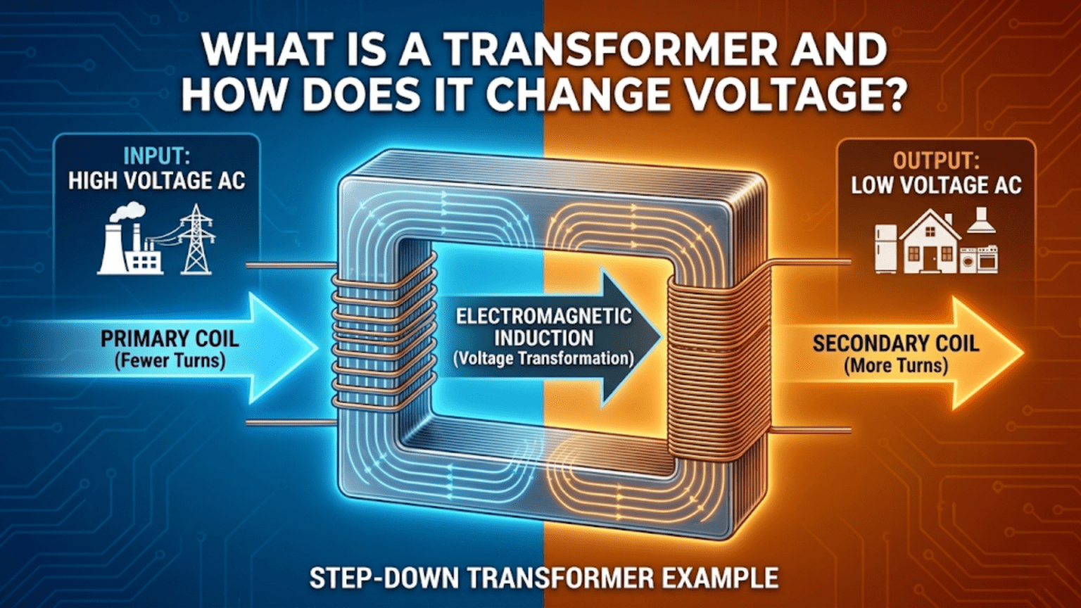
A transformer is a passive electrical component that transfers electrical energy between two or more circuits through electromagnetic induction, changing the voltage level in the process. It consists of two or more coils of wire (windings) wrapped around a shared magnetic core. When AC current flows through the primary winding, it creates a changing magnetic field in the core; this changing field induces a voltage in the secondary winding. The ratio of output voltage to input voltage equals the ratio of the number of turns in each winding—the turns ratio. A transformer with 100 primary turns and 1,000 secondary turns steps voltage up by 10×; one with 1,000 primary and 100 secondary steps it down by 10×. Transformers only work with AC—they cannot change DC voltages.
Introduction: The Device That Powers the Modern World
Before electricity could be distributed across cities and countries, it faced a fundamental engineering problem. Transmitting electrical power over long distances requires high voltages—because at high voltage, the same power travels through thinner wires with less current, reducing resistive losses in proportion to the square of the current. But high voltages are dangerous for home and industrial use; appliances need low, safe voltages.
The solution to this contradiction is the transformer. At power stations, transformers step voltage up from generation levels (10,000–25,000V) to transmission levels (115,000–765,000V) for long-distance travel. At substations, other transformers step it back down to distribution levels (4,000–25,000V). At the street or building level, distribution transformers step it down again to the 120V or 240V that reaches homes and businesses. The entire modern electrical grid—the infrastructure that powers virtually every device you own—exists because transformers can change voltage levels efficiently.
But transformers aren’t only for power grids. They appear in the power supply inside every mains-powered electronic device, in audio equipment for impedance matching, in RF circuits for coupling and matching, in measurement systems for safety isolation, in data communication for common-mode noise rejection, and in countless industrial applications. They are simultaneously one of the oldest electrical components (Michael Faraday demonstrated the principles in 1831) and one of the most pervasive.
Understanding transformers means understanding electromagnetic induction—the beautiful physical relationship between changing magnetic fields and induced voltages that is at the heart of electric generators, electric motors, and countless other devices. It means understanding turns ratios, power conservation, impedance transformation, and the practical differences between transformer types. And it means understanding where and why designers choose transformers over other voltage conversion approaches.
This comprehensive guide builds complete transformer understanding from electromagnetic first principles through practical design. We’ll explore the physics of induction, derive the turns ratio relationship, examine how transformers conserve power while changing voltage, discuss losses and efficiency, survey the major transformer types and their applications, and connect everything to practical circuit design.
Part 1: The Physics of Electromagnetic Induction
Faraday’s Law: The Foundation
The transformer operates on Michael Faraday’s law of electromagnetic induction, discovered in 1831:
A changing magnetic field through a conductor induces a voltage (EMF) in that conductor.
More precisely, the induced voltage equals the rate of change of magnetic flux through the conductor:
V = -N × dΦ/dt
Where:
- V = induced voltage (volts)
- N = number of turns of wire in the coil
- Φ = magnetic flux through the coil (webers)
- dΦ/dt = rate of change of flux (webers per second)
- The negative sign indicates the induced voltage opposes the change (Lenz’s law)
The key insight: The induced voltage is proportional to both the rate of flux change AND the number of turns. More turns = more voltage induced by the same changing flux.
Why Transformers Need AC
Consider what happens with DC and AC applied to a primary winding:
With DC: A DC current creates a static magnetic field. Static means dΦ/dt = 0. Therefore, the induced secondary voltage = 0. No energy is transferred to the secondary. The primary winding is just a resistor, eventually heating up from I²R losses.
With AC: An AC current creates a continuously changing magnetic field—the field strength rises and falls with the AC waveform. This changing flux induces a continuous AC voltage in the secondary. Energy is transferred every half-cycle as the flux changes in both directions.
This is the fundamental reason transformers only work with AC. It is not a design limitation or engineering shortcoming—it is a direct consequence of Faraday’s law. DC transformers don’t exist as passive devices; DC voltage conversion requires active electronics (like switch-mode power supplies).
Mutual Inductance: The Coupling Mechanism
When two coils share a magnetic core, the magnetic flux from one coil threads through the other. This mutual coupling is characterized by the mutual inductance M:
V₂_induced = M × dI₁/dt
In a tightly coupled transformer (high-permeability core, minimal leakage flux): M ≈ √(L₁ × L₂)
The coupling coefficient k (0 to 1) measures how efficiently flux from one coil links to the other: k = M / √(L₁ × L₂)
A perfect transformer has k = 1 (all flux from primary links to secondary). Real transformers have k = 0.95–0.999 depending on core material and winding technique.
Part 2: The Turns Ratio — How Voltage Changes
Deriving the Turns Ratio
In an ideal transformer with perfect magnetic coupling (k = 1), all the magnetic flux produced by the primary winding passes through the secondary winding. Using Faraday’s law:
Primary winding: V₁ = N₁ × dΦ/dt
Secondary winding (same dΦ/dt since shared core): V₂ = N₂ × dΦ/dt
Dividing: V₂/V₁ = N₂/N₁
This is the fundamental transformer equation. The voltage ratio equals the turns ratio.
The turns ratio a: a = N₁/N₂ = V₁/V₂
- If N₂ > N₁: Step-up transformer (secondary voltage > primary voltage)
- If N₂ < N₁: Step-down transformer (secondary voltage < primary voltage)
- If N₂ = N₁: 1:1 isolation transformer (voltages equal, but circuits electrically isolated)
Worked Examples
Example 1: Step-down transformer for electronics Primary: N₁ = 2,000 turns, V₁ = 240V AC (mains) Secondary: N₂ = 83 turns V₂ = V₁ × (N₂/N₁) = 240V × (83/2,000) = 240V × 0.0415 = 9.96V ≈ 10V AC
This is a typical transformer in a small wall adapter, stepping 240V mains down to 10V AC for rectification.
Example 2: Grid step-up transformer Primary: V₁ = 11,000V (generator output), N₁ = 1,100 turns Secondary: N₂ = 13,000 turns V₂ = 11,000V × (13,000/1,100) = 11,000V × 11.82 = 130,000V = 130kV
This steps the generator voltage up for long-distance transmission.
Example 3: Audio output transformer Primary: 5,000Ω impedance load (tube amplifier output) Secondary: 8Ω (loudspeaker) Required turns ratio: a = √(Z₁/Z₂) = √(5,000/8) = √625 = 25:1 N₁/N₂ = 25, so if N₁ = 500 turns, N₂ = 20 turns
The Current Relationship: Conservation of Power
While voltage changes in proportion to turns ratio, current changes inversely:
I₁/I₂ = N₂/N₁ = 1/a
Or equivalently: I₂/I₁ = N₁/N₂ = a
A step-down transformer that halves the voltage doubles the current (and vice versa).
Why? Power conservation: An ideal transformer has 100% efficiency—no power is created or destroyed: P₁ = P₂ V₁ × I₁ = V₂ × I₂
If V₂ = V₁/2 (step-down by 2), then I₂ = 2 × I₁ (current doubles).
Summary of transformer relationships:
| Turns ratio (N₁:N₂) | Voltage ratio (V₁:V₂) | Current ratio (I₁:I₂) |
|---|---|---|
| 1:2 (step-up 2×) | 1:2 | 2:1 |
| 1:10 (step-up 10×) | 1:10 | 10:1 |
| 2:1 (step-down 2×) | 2:1 | 1:2 |
| 10:1 (step-down 10×) | 10:1 | 1:10 |
| 1:1 (isolation) | 1:1 | 1:1 |
Part 3: Impedance Transformation
One of the transformer’s most powerful but often overlooked capabilities is impedance transformation. This is why transformers are indispensable in audio systems and RF circuits.
The Impedance Transformation Formula
When a load impedance Z_L is connected to the secondary, the impedance seen at the primary (Z_in) is:
Z_in = a² × Z_L = (N₁/N₂)² × Z_L
The impedance is transformed by the square of the turns ratio.
Why the square? Impedance = V/I. Voltage scales by a (turns ratio); current scales by 1/a. Therefore: Z_primary = V₁/I₁ = (a × V₂) / (I₂/a) = a² × (V₂/I₂) = a² × Z_L
Example: Audio output transformer A vacuum tube amplifier has an output impedance of 5,000Ω (internal plate resistance of the output tube). To drive an 8Ω loudspeaker for maximum power transfer, we need to transform the speaker’s 8Ω up to 5,000Ω as seen from the primary.
Required a² = Z_primary / Z_secondary = 5,000 / 8 = 625 Required a = √625 = 25 Turns ratio: N₁:N₂ = 25:1
With this transformer, the amplifier “sees” 5,000Ω (matched to its output impedance) while the speaker receives power through the 25:1 step-down winding.
Part 4: Transformer Construction and Core Materials
The Basic Construction
Every transformer consists of:
1. Primary winding: Coil of wire connected to the AC source. The number of turns (N₁) sets the voltage transformation ratio with the secondary.
2. Secondary winding: Coil of wire from which transformed voltage is taken. May have multiple separate secondary windings for multiple output voltages.
3. Magnetic core: Concentrates the magnetic flux generated by the primary and guides it through the secondary. The core material determines efficiency, frequency range, and power handling.
4. Insulation: Separates windings from each other and from the core. Sets the voltage isolation rating—critical for mains-connected transformers.
5. Enclosure/bobbin: Mechanical support for the windings.
Core Materials and Their Frequency Ranges
Silicon steel laminations: The standard core material for 50/60Hz power transformers. Thin laminations (0.3–0.5mm) insulated from each other reduce eddy current losses at power frequencies. Good magnetic permeability (~1,000–5,000 times that of air).
Used in: Mains power transformers, distribution transformers, large toroidal transformers
Ferrite: A ceramic magnetic material combining iron oxide with other metal oxides (zinc, nickel, manganese). Ferrite has much lower conductivity than steel (very low eddy current losses), making it effective at high frequencies (10kHz–100MHz+). Lower saturation flux density than silicon steel.
Used in: Switch-mode power supply transformers, RF transformers, ferrite bead inductors, high-frequency coupled inductors
Amorphous metal (Metglas): An amorphous (non-crystalline) iron-based alloy with very low hysteresis and eddy current losses. More expensive than silicon steel but significantly more efficient, especially at higher power levels.
Used in: High-efficiency distribution transformers, high-performance audio transformers
Powdered iron: Iron powder in a non-conducting binder. Lower permeability than ferrite but more stable over frequency and temperature. Good for moderate-frequency inductors (100kHz–30MHz).
Used in: Switching supply filter inductors, RF chokes
Air core: No magnetic material at all—just wire coils. Low inductance but no core losses and no saturation limit. Suitable only for very high-frequency (>50MHz) RF transformers.
Used in: RF matching transformers, baluns at VHF and UHF
Core Geometry
E-I laminations: Most common for low-frequency power transformers. E-shaped and I-shaped stampings interleave to form the core, with the primary and secondary wound on the center leg.
Toroidal core: Donut-shaped core that provides excellent magnetic efficiency (low leakage flux), compact size, and low external magnetic field (good for audio applications). More expensive to wind but preferred for audio and high-efficiency power applications.
Pot core: Enclosed cup-shaped ferrite core providing low electromagnetic interference. Used in high-frequency switching transformers.
EE, EF, ETD cores: Various ferrite core geometries optimized for switching power supply transformers.
Part 5: Real Transformer Behavior and Losses
Why Real Transformers Aren’t Ideal
The ideal transformer we’ve discussed has 100% efficiency and perfect coupling. Real transformers lose some energy and have imperfect coupling. Understanding these deviations helps in selection and application.
Copper Losses (I²R Losses)
The resistance of the wire in both windings dissipates power: P_copper = I₁² × R₁ + I₂² × R₂
Minimizing copper losses:
- Use larger diameter (lower resistance) wire
- Minimize total winding length (compact design)
- Use multiple strands (Litz wire) at high frequencies to overcome skin effect
Core Losses
Hysteresis losses: The magnetic domains in the core material are repeatedly reversed with each AC cycle, consuming energy. Proportional to frequency × (flux density)^n (where n ≈ 1.6–2 for silicon steel).
Eddy current losses: The changing flux induces small circulating currents (eddy currents) in the conducting core material, which dissipate power as heat. Proportional to frequency² × (flux density)².
Minimizing core losses:
- Laminated cores reduce eddy currents (current must cross insulating layer)
- High-permeability materials reduce flux density needed for given voltage
- Ferrite cores have inherently low eddy current losses (resistive material)
- Operate at lower flux density (use larger core)
Leakage Flux and Leakage Inductance
Not all magnetic flux from the primary passes through the secondary. Flux that “leaks” out and doesn’t link to the secondary is called leakage flux, and it causes leakage inductance.
Effect of leakage inductance: Leakage inductance appears in series with the windings and causes voltage to drop at higher currents and frequencies (acting as an impedance). In switch-mode supplies, leakage inductance causes voltage spikes during switching (must be clamped with snubber circuits).
Magnetizing Current
Even with no load on the secondary, a real transformer draws some current from the primary to establish the magnetic flux in the core. This magnetizing current is reactive (90° out of phase with voltage) and does not perform useful work but does affect power factor and causes some core heating.
Efficiency
Real power transformer efficiency: η = P_out / P_in = P_out / (P_out + P_copper + P_core)
Typical efficiency:
- Small signal transformer (audio): 85–95%
- Mains power transformer (wall adapter): 85–95%
- Large power distribution transformer: 97–99.7%
- Switch-mode transformer (high-frequency ferrite): 90–98%
Large transformers are more efficient partly because losses are proportional to surface area while power handling scales with volume—bigger transformers have proportionally lower losses.
Part 6: Transformer Types and Applications
Mains Power Transformers
The most familiar transformer type, converting mains AC (120V or 240V at 50/60Hz) to lower AC voltages for electronics.
Laminated EI or toroidal construction Typical secondary voltages: 6V, 9V, 12V, 15V, 18V, 24V (before rectification) VA rating: Apparent power capacity (volts × amps)
Application in power supplies: Transformer secondary → Bridge rectifier → Filter capacitor → Voltage regulator → DC output
The transformer provides both voltage step-down and isolation from the mains—the secondary is not connected to the mains ground, providing safety separation.
Isolation Transformers
A 1:1 transformer (same number of primary and secondary turns) provides voltage isolation without changing voltage level.
Why isolation matters:
- Safety: Secondary circuits not connected to mains earth ground
- Noise rejection: Common-mode noise from mains doesn’t couple to secondary
- Equipment protection: Ground loops broken between equipment
Applications:
- Medical equipment (patient safety—any fault to ground limited to safe levels)
- Laboratory bench isolation transformers
- Audio equipment (breaking ground loops that cause hum)
- Measurement equipment connected to mains-powered devices under test
Autotransformers
An autotransformer uses a single tapped winding rather than separate primary and secondary windings. Part of the winding is shared between primary and secondary:
     N₁ total turns
     ┌──────────────┐
     │              │
 V₁ in           V₂ out
     │    N₂        │
     └──────────────┘← Tap
Advantages: More compact and efficient than two-winding transformer for small voltage ratios Disadvantages: No electrical isolation (primary and secondary share a winding—mains voltage can appear on secondary) Applications: Variac (variable autotransformer), small voltage adjustment, motor starting
Safety note: Autotransformers are NOT suitable anywhere isolation from mains is required. Never use them in safety-critical applications.
Audio Transformers
Designed for the audio frequency band (20Hz–20kHz) with demanding linearity requirements:
Types:
- Microphone input transformer: Balances unbalanced microphone signal (XLR) to balanced differential input; provides impedance matching; 150Ω:1,500Ω typical
- Line-level transformer: 600Ω:600Ω balanced interconnection; breaks ground loops; widely used in professional audio
- Output transformer: Matches high-impedance tube amplifier output to low-impedance loudspeaker; critical for tube hi-fi and guitar amplifiers
- Interstage transformer: Couples between amplifier stages in high-end tube equipment
Key audio transformer specifications:
- Frequency response: Should be flat (±1–3dB) from 20Hz to 20kHz
- Total harmonic distortion (THD): Must be very low to preserve audio quality
- Primary inductance: Must be sufficiently high that low-frequency response (20Hz) is maintained
- Leakage inductance: Must be low for flat high-frequency response
RF Transformers and Baluns
High-frequency transformers and baluns (balanced-to-unbalanced converters) used in RF and communications:
Impedance matching transformers: Match antenna impedance (typically 50–300Ω) to transmission line or receiver input impedance
Baluns: Convert between balanced (differential, no ground reference) and unbalanced (single-ended, ground-referenced) signal formats
- Used at antenna feedpoints (dipole is balanced; coaxial cable is unbalanced)
- Wound on ferrite cores; function from MF through UHF depending on core material
RF transformers: Couple signals between RF circuits with impedance transformation; used in mixers, amplifiers, filters
Common construction: Bifilar winding (two wires wound simultaneously) on ferrite toroid provides tight coupling and broad bandwidth
Switch-Mode Power Supply Transformers
High-frequency ferrite transformers in switching power supplies (SMPS) operate at 50kHz–1MHz, enabling dramatically smaller size compared to 50/60Hz equivalents:
Why high frequency enables smaller transformers: Transformer size is determined by the amount of flux storage needed. Higher frequency = more cycles per second = less flux per cycle needed = smaller core.
A 100W transformer at 50Hz might be 300g and 10×10×8cm. The same power at 100kHz: perhaps 30g and 3×3×2cm.
Construction: Ferrite EE, EF, or ETD cores; tight winding layout to minimize leakage inductance; Litz wire for high-frequency winding to reduce skin effect losses
Applications: Phone chargers, laptop adapters, LED drivers, desktop PC power supplies, industrial SMPS
Part 7: Practical Transformer Selection and Use
Selecting a Mains Transformer
Step 1: Determine secondary voltage needed Account for:
- Rectified output = V_secondary × 1.414 (peak of sinusoid) minus two diode drops (≈1.4V for bridge)
- Ripple: Actual DC output will be lower due to filter capacitor size
- Regulator dropout: Linear regulator needs additional headroom (typically 2–3V)
For 12V regulated DC output with 7812 regulator (2.5V dropout): Required minimum DC = 12 + 2.5 = 14.5V After ripple (assume 1V ripple): Minimum rectified peak = 15.5V Transformer secondary = 15.5V / 1.414 = 10.97V → Choose 12V secondary
Step 2: Determine VA rating needed VA = V_secondary × I_secondary_maximum
For 1A load at 12V secondary: VA = 12 × 1 = 12VA Add 20–30% margin for efficiency and peak current: Choose 15VA or 20VA transformer
Step 3: Check physical constraints Mounting type (PCB, chassis, panel), case size, weight, cooling requirements
Transformer Safety Considerations
Mains isolation is a safety function: A properly specified isolation transformer keeps dangerous mains voltages away from the secondary circuit. Never bypass or short the transformer’s isolation.
Insulation class: Transformers are rated by their insulation class and maximum working voltage. Use transformers rated for the appropriate class:
- Class II (double insulation): No earth ground required; used in portable equipment
- Reinforced insulation: Meets strict safety standard for medical or hazardous environments
Fusing: Always fuse the primary (mains input) side of a transformer. A fault in the secondary that draws excessive primary current will blow the fuse before the transformer overheats.
Thermal protection: Many quality power transformers include a thermal fuse or thermal cutout that permanently disconnects the winding if overheated. These are safety devices and should not be bypassed.
Inrush current: When a transformer is first energized, a brief inrush current (2–15× rated current) flows as the core magnetizes. Circuit breakers and fuses must be rated to allow this inrush without tripping.
Comparison Table: Transformer Types
| Type | Frequency | Core | Turns Ratio | Key Feature | Typical Applications |
|---|---|---|---|---|---|
| Mains power | 50–60 Hz | Laminated silicon steel | 10:1 to 50:1 step-down | Safety isolation, voltage step-down | Wall adapters, linear power supplies |
| Isolation (1:1) | 50–60 Hz | Laminated silicon steel | 1:1 | Electrical isolation, no voltage change | Medical, lab safety, audio hum removal |
| Toroidal | 50–60 Hz | Toroidal laminations | Any | Low leakage flux, compact, quiet | Audio, precision instruments |
| Autotransformer | 50–60 Hz | Laminated or toroidal | Close to 1:1 | Efficient, compact, no isolation | Variac, small voltage adjustment |
| Audio signal | 20 Hz–20 kHz | Silicon steel or amorphous | Various | Flat response, low THD | Microphone input, line level, tube output |
| RF/Balun | 1 MHz–1 GHz | Ferrite toroid | Various | Broadband, balanced/unbalanced | Antenna matching, RF coupling |
| SMPS ferrite | 50 kHz–1 MHz | Ferrite (EE, ETD, pot) | Various | High frequency = compact | Phone chargers, PC supplies, LED drivers |
| Pulse/gate drive | 10 kHz–1 MHz | Ferrite | 1:1 to 1:4 | Isolated gate drive | MOSFET/IGBT gate isolation |
| Current transformer | 50 Hz–1 kHz | Toroidal (split-core) | 1:1000 typical | Measures current without breaking circuit | Power metering, current sensing |
Conclusion: Elegant Physics in Everyday Hardware
The transformer is a beautiful device. It has no moving parts, requires no power supply of its own, and works silently and reliably for decades. Yet it performs one of the most useful functions in electrical engineering: changing voltage levels efficiently while maintaining power and providing electrical isolation. It does all of this through nothing more than wound wire and carefully chosen iron—harnessing Faraday’s law directly.
The Core Principles
Electromagnetic induction is the mechanism. Changing magnetic flux from the primary winding induces voltage in the secondary. No changing flux, no output—this is why transformers work only on AC.
Turns ratio determines voltage transformation. V₂/V₁ = N₂/N₁. This simple ratio governs everything about transformer voltage behavior. More turns on the secondary means higher voltage; fewer turns means lower voltage.
Power is conserved, not created. A transformer cannot create power. Higher voltage means proportionally lower current; lower voltage means higher current. P = V × I stays constant (minus losses).
Impedance transforms as turns ratio squared. Z_in = (N₁/N₂)² × Z_load. This impedance transformation property is as important as voltage transformation in audio and RF applications.
Core material determines frequency range. Silicon steel for power frequencies; ferrite for high frequencies. The choice of core material is the primary design decision that determines what frequency range a transformer can serve.
Where You’ll Find Transformers
Every time you plug in a mains-powered device, a transformer is at work—either a traditional laminated transformer in older equipment or a high-frequency ferrite transformer inside a switch-mode power supply. Every professional audio system uses multiple transformers for impedance matching and isolation. Every radio transmitter uses RF transformers for antenna matching. The electrical grid that powers civilization consists largely of increasingly large transformers stepping voltage up and down between generation and use.
The transformer is not a component you’ll design from scratch in most hobbyist applications—you’ll select one from a manufacturer’s catalog. But understanding how it works, what the specifications mean, what isolation it provides, and when to use it versus other voltage conversion approaches is fundamental knowledge for anyone who designs, builds, or repairs electronics that connects to the real world.
From Faraday’s wrapping wire around an iron ring in 1831 to the billions of switch-mode adapters charging phones worldwide today, the transformer remains irreplaceable—a masterpiece of applied electromagnetic physics that quietly powers everything.