Introduction
Few concepts in electronics generate as much confusion among beginners as “ground.” The term appears constantly in circuit discussions, schematics show ground symbols everywhere, and troubleshooting advice frequently mentions checking grounds. Yet for many learners, ground remains a vague, poorly understood concept shrouded in mystery. Is ground the earth beneath our feet? Is it the negative terminal of a battery? Is it a wire, a connection point, or something more abstract? Why do circuits need ground, and what happens when grounding is incorrect?
The confusion surrounding ground is understandable because the term “ground” actually refers to several related but distinct concepts depending on context. Earth ground, chassis ground, signal ground, digital ground, analog ground, and virtual ground all appear in electronics literature, each with specific meanings and applications. Making matters worse, schematics often use ground symbols without clarifying which type of ground they represent, leaving beginners to puzzle out the meaning from context.
Understanding ground thoroughly is not optional for anyone serious about electronics. Incorrect grounding causes countless problems: circuits that malfunction mysteriously, noise that degrades signal quality, safety hazards from improper earth grounding, and damage from ground loops and voltage differences. Conversely, proper grounding ensures safe operation, minimizes interference, provides stable voltage references, and enables reliable circuit function. This comprehensive guide will clarify what ground means in various contexts, explain why grounding matters, and provide practical guidance for implementing proper grounding in your circuits.
Ground as a Voltage Reference: The Fundamental Concept
At its most fundamental level in circuit theory, ground represents the zero-volt reference point against which all other voltages in a circuit are measured. This definition, while technically correct, requires substantial elaboration to become practically useful.
The Relativity of Voltage
Voltage is not an absolute quantity but a potential difference between two points. When we say a point in a circuit is at “5 volts,” we implicitly mean it is 5 volts higher than some reference point. Without specifying that reference, the voltage measurement is meaningless. Is it 5 volts above earth potential? Above the negative battery terminal? Above some arbitrary point we have designated as reference?
Ground provides the reference point that makes voltage measurements meaningful. When a schematic labels a node as “+5V,” it means that node is 5 volts more positive than ground. When another node is labeled “-12V,” it is 12 volts more negative than ground. Ground itself, by definition, is at 0 volts—not because it has zero absolute potential (which is meaningless), but because we have chosen it as our reference.
Choosing the Ground Reference
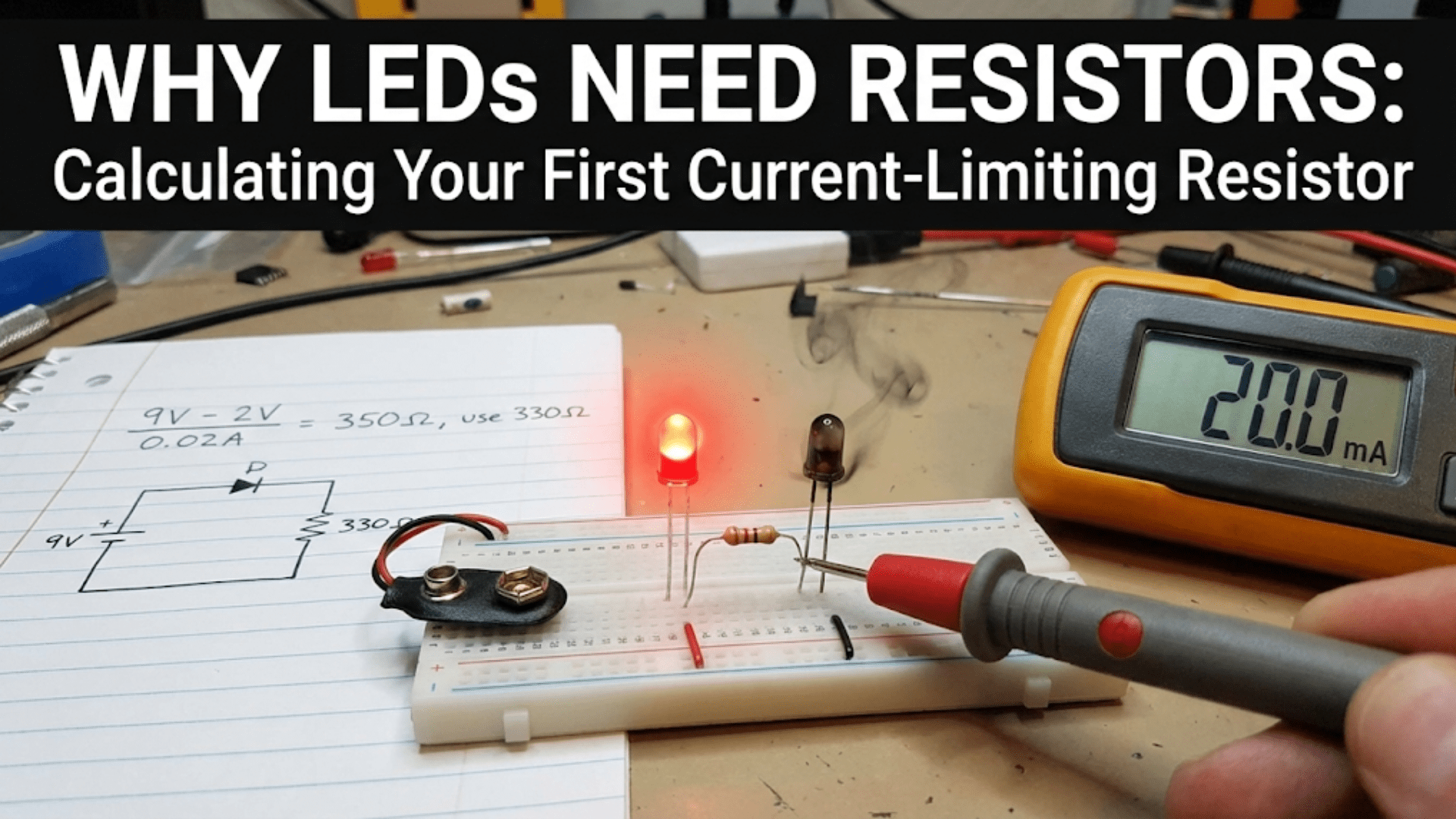
In battery-powered circuits, the negative battery terminal typically serves as ground reference. All voltages are measured relative to this point. The positive terminal of a 9-volt battery is then at +9V relative to ground, while the negative terminal is at ground (0V). This choice is arbitrary—we could equally designate the positive terminal as ground, making it 0V and the negative terminal -9V. The circuit would function identically; only our voltage labels would change.
This arbitrariness reveals an important insight: ground is a choice we make for convenience, not an inherent property of the circuit. We typically choose ground to make voltage labels simple and intuitive. For circuits with positive and negative supply voltages (like ±15V for operational amplifiers), we often designate the midpoint as ground, giving us +15V, 0V (ground), and -15V references. This symmetric arrangement simplifies circuit analysis and component selection.
Ground as a Return Path
Beyond serving as voltage reference, ground provides the return path for current flow. In a simple LED circuit with a battery, resistor, and LED in series, current flows from the battery’s positive terminal through the resistor and LED, then must return to the battery’s negative terminal to complete the circuit. If we designate the negative terminal as ground, the current return path is through the ground connection.
This return path function is not merely conceptual—it has physical reality. The wire or trace connecting components to the ground reference must actually carry all the return current from those components. If this ground connection has significant resistance or inductance, voltage drops occur in the ground path, creating ground potential differences that can cause circuit malfunction. Understanding ground as both reference and current return path helps avoid these problems.
Different Types of Ground: Context Matters
The term “ground” encompasses several distinct concepts that must be distinguished for clear understanding and proper circuit design.
Earth Ground: The Safety Reference
Earth ground, also called protective earth or safety ground, refers to a literal connection to the earth through a grounding electrode—typically a metal rod driven into the soil or a connection to a building’s grounding system. This provides a reference to the actual electrical potential of the earth, which we define as zero volts for safety purposes.
Earth ground serves critical safety functions in AC-powered equipment. The safety ground wire (green or green-yellow insulated wire in most countries) connects equipment metal enclosures to earth ground. If a fault causes live voltage to appear on the enclosure, fault current flows to earth through this connection, tripping circuit breakers or fuses and removing the hazardous voltage before someone touches the enclosure.
Earth ground also provides a reference for measuring voltage levels in power distribution systems. The neutral conductor in residential wiring connects to earth ground at the service entrance, establishing a known reference potential. This ensures that even if the hot conductor voltage varies, the neutral remains at or near earth potential, limiting the maximum voltage to which people might be exposed.
Chassis Ground: The Metal Enclosure
Chassis ground refers to the metal enclosure or chassis of equipment. In most AC-powered equipment, chassis ground connects to earth ground through the safety ground wire. However, chassis ground and earth ground are not synonymous—the chassis is simply a conductor connected to earth, with resistance and inductance in that connection causing small but sometimes significant voltage differences.
In battery-powered portable equipment, chassis ground might not connect to earth at all. The metal case might serve as a shield against electromagnetic interference or might provide a convenient common connection point, but without AC power connection, true earth ground is absent. In such equipment, “chassis ground” is really just a convenient electrical common point rather than a safety earth reference.
Signal Ground: The Circuit Reference
Signal ground, also called circuit ground or common, provides the voltage reference for circuit operation. In most circuits, signal ground connects to one terminal of the power supply (typically negative for single-supply circuits) and serves as the 0V reference for all voltage measurements and signal processing.
Signal ground might or might not connect to earth ground depending on the application. In AC-powered equipment, signal ground often connects to earth ground through the power supply, though sometimes a high-value resistor or small capacitor provides the earth connection for safety while isolating the signal ground from earth noise. In battery-powered equipment, signal ground floats relative to earth, having no direct earth connection.
Digital Ground and Analog Ground
In mixed-signal circuits containing both digital and analog sections, designers sometimes create separate digital ground and analog ground systems that connect at a single point. Digital circuits create noise through rapid switching, causing current spikes in ground connections. If analog circuits share these noisy ground connections, the noise couples into sensitive analog signals causing errors.
Separating grounds allows digital noise to remain in the digital ground system while analog signals reference the quieter analog ground. The two ground systems connect at a single point—often at the power supply—preventing ground loops while isolating noise. This separation may be physical (separate traces or wires) or may exist only in careful layout that minimizes shared ground impedance.
Virtual Ground: Not Really Ground At All
Virtual ground refers to circuit nodes maintained at ground potential by active circuitry despite not being physically connected to ground. In an inverting operational amplifier configuration, the inverting input sits at virtual ground—the feedback forces it to ground potential even though it connects to ground only through very high impedance.
Virtual grounds enable circuit configurations impossible with direct ground connections. They provide ground reference without current flow to actual ground, allowing signal processing while maintaining DC isolation. However, calling them “ground” is somewhat misleading since they lack the current-carrying capability of true ground connections.
Why Grounding Matters: Practical Implications
Proper grounding is not merely theoretical nicety but has profound practical implications for circuit function, safety, and reliability.
Voltage Reference Stability
Circuits require stable voltage references to function correctly. If ground potential varies, all circuit voltages referenced to ground vary with it, potentially causing malfunction. Consider a comparator circuit that switches when input voltage exceeds a 2.5V reference. If ground potential shifts by 100 millivolts due to current flow through a high-resistance ground connection, the effective threshold shifts to 2.4V or 2.6V depending on shift direction.
This ground bounce, as it is often called, affects all circuits sharing the unstable ground. Digital circuits might experience false triggering. Analog circuits might suffer noise and offset errors. Voltage regulators might produce incorrect output voltages. Maintaining low-impedance ground connections ensures ground potential remains stable despite varying current flow.
Current Return Paths
Every current flowing in a circuit must return to its source, and ground typically provides this return path. The impedance of the ground return path directly affects circuit performance. High ground impedance causes voltage drops in the return path, creating the ground potential differences discussed above.
Consider a power supply ground that must carry return current from multiple circuits. If one circuit suddenly demands increased current, the voltage drop in the shared ground impedance increases, shifting ground potential for all circuits sharing that ground. This can couple noise from one circuit into others, causing crosstalk and interference. Low-impedance ground connections minimize these interactions.
Safety and Shock Hazard Prevention
Earth grounding prevents dangerous voltages from appearing on equipment enclosures that people might touch. Without earth grounding, a fault that energizes an enclosure creates a shock hazard—touching the enclosure and ground simultaneously completes a circuit through the human body. The earth ground connection provides a low-resistance path for fault current, causing protective devices to operate and remove the hazard.
Ground fault circuit interrupters (GFCIs) detect current imbalance between hot and neutral conductors, indicating some current is returning through an unintended path—possibly through a person touching energized parts. The GFCI trips within milliseconds, preventing potentially lethal shock. This protection relies on proper earth grounding to provide the unintended current path that the GFCI detects.
Electromagnetic Compatibility
Proper grounding is essential for electromagnetic compatibility—ensuring circuits neither emit excessive interference nor suffer from external interference. Ground planes provide low-impedance return paths for high-frequency currents, reducing loop areas that radiate and receive electromagnetic fields. Shields connected to ground at appropriate points block external interference while containing internal emissions.
However, incorrect grounding can worsen EMC problems. Multiple ground connections can create ground loops where circulating currents flow between different ground points at different potentials, radiating interference and picking up noise. Understanding proper grounding techniques prevents these issues and ensures electromagnetic compatibility.
Common Grounding Mistakes and Problems
Several grounding errors appear repeatedly in beginner circuits, causing problems ranging from subtle malfunction to catastrophic failure.
The Floating Ground Problem
A floating ground occurs when the ground reference point lacks adequate current capacity or has excessive impedance to the actual current return path. For example, connecting ground through a thin wire that must carry substantial return current creates voltage drops that vary with current, making ground potential unstable.
The solution is ensuring ground connections have adequate current-carrying capacity—typically achieved by using wide PCB traces, thick wires, or dedicated ground planes. The ground path should have impedance as low as practically achievable, approaching ideal zero-impedance reference.
Ground Loops: Multiple Paths Create Problems
A ground loop occurs when two points designated as ground connect through multiple paths with different impedances. Current circulating between these paths creates voltage differences between supposedly identical ground points, coupling noise and creating potential oscillation paths.
Consider two pieces of equipment connected by a signal cable with its shield grounded at both ends. If the equipment enclosures also connect through earth ground or another chassis connection, two parallel ground paths exist. Any noise voltage in one ground creates circulating current in the loop, inducing noise in the signal circuit. Breaking one ground connection eliminates the loop and the associated noise.
Sharing Ground Between High and Low Power Circuits
When high-current and low-current circuits share ground connections, current from the high-power circuit creates voltage drops in the shared ground impedance that appear as noise in the low-power circuit. A motor driver pulling 10 amps through a 0.01-ohm shared ground creates 100 millivolts of ground noise that can completely swamp a 1-millivolt sensor signal sharing that ground.
The solution is star grounding, where low-current signal grounds connect directly to the reference point without sharing paths with high-current grounds. This minimizes coupling between circuits despite them sharing the same ultimate ground reference.
Long Ground Connections
Long ground wires or narrow ground traces have inductance that opposes rapid current changes, creating voltage spikes during transients. At high frequencies, even the resistance of long ground connections becomes problematic as the effective impedance increases. A ground connection that works fine for DC or low-frequency signals may be completely inadequate for high-frequency digital or RF circuits.
Local decoupling capacitors provide nearby current sources for rapid transients, reducing current that must flow through long ground connections. Ground planes provide low-inductance current return paths that minimize voltage variations even during rapid current changes. Recognizing that ground impedance increases with frequency helps avoid high-frequency grounding problems.
Assuming All Grounds Are Equal
Different ground symbols in schematics might represent different physical ground systems. Chassis ground, earth ground, and signal ground might all appear but refer to distinct connection points. Connecting all these grounds together incorrectly can create ground loops, safety hazards, or circuit malfunction.
Always verify which ground a symbol represents and whether different grounds should actually connect or remain isolated. Some equipment intentionally isolates signal ground from chassis ground for safety or noise reasons. Connecting them defeats the design intent and may create hazards or degrade performance.
Proper Grounding Techniques
Understanding grounding problems guides proper grounding implementation that avoids these issues.
Star Grounding for Mixed Circuits
Star grounding routes all ground returns to a single central point, preventing different circuits from sharing ground paths. High-current grounds, low-current signal grounds, and sensitive analog grounds all connect at the star point but nowhere else. This prevents current from one circuit creating voltage drops in another circuit’s ground path.
The star point should be at the power supply or, in complex systems, at the point where power enters each subsystem. From the star point, separate ground connections run to each circuit section. While this creates multiple ground wires or traces, it ensures isolation between circuits and prevents ground current from one circuit affecting another.
Ground Planes for High-Speed Circuits
A ground plane—a large continuous area of copper connected to ground—provides the lowest possible impedance ground connection. In PCB design, dedicating an entire layer to ground creates a ground plane that offers numerous benefits: low resistance, low inductance, consistent impedance, and excellent high-frequency performance.
Signal traces running over a ground plane have controlled impedance and minimal radiation. Return currents flow in the ground plane directly beneath signal traces, minimizing loop area and electromagnetic emissions. The large copper area provides excellent heat dissipation and uniform voltage reference. Modern high-speed digital and RF designs almost universally use ground planes for these reasons.
Single-Point Grounding for Low-Frequency Circuits
In low-frequency circuits where current paths and inductance are less critical, single-point grounding connects all grounds together at one location. This prevents ground loops while ensuring all grounds share the same reference potential. The technique works well for audio circuits, sensor systems, and other applications operating below about 1 MHz.
The single ground point should be physically located where it minimizes the maximum distance any circuit must connect to reach ground. Long ground connections increase resistance and inductance, degrading performance. Careful thought about ground point location optimizes the compromise between minimizing connection lengths and maintaining single-point connection.
Multi-Point Grounding for High-Frequency Circuits
At high frequencies where wavelengths become comparable to circuit dimensions, single-point grounding fails because the ground connection length introduces significant impedance. Multi-point grounding connects ground to the reference at multiple locations, keeping any ground connection short relative to wavelength.
The tradeoff is that multi-point grounding can create ground loops at lower frequencies where the connections appear as multiple parallel paths. Proper high-frequency grounding often uses multi-point connections for high frequencies while maintaining effective single-point connection at low frequencies through careful impedance management.
Isolated Grounds for Noise Reduction
Some systems use isolated grounds where signal ground intentionally floats relative to earth ground with only a high-impedance connection (large resistor or small capacitor) linking them. This isolation prevents ground noise from AC power systems from coupling into sensitive signal circuits while maintaining the safety benefits of earth connection.
The high-impedance connection provides a DC path preventing dangerous charge buildup while presenting high impedance to AC noise, blocking its transmission between ground systems. Regulatory safety requirements often specify maximum permitted resistance in this connection, limiting how much isolation can be achieved while maintaining safety compliance.
Ground Symbols in Schematics
Schematics use various symbols to represent different ground types, though unfortunately not all schematics follow consistent conventions.
The Standard Ground Symbol
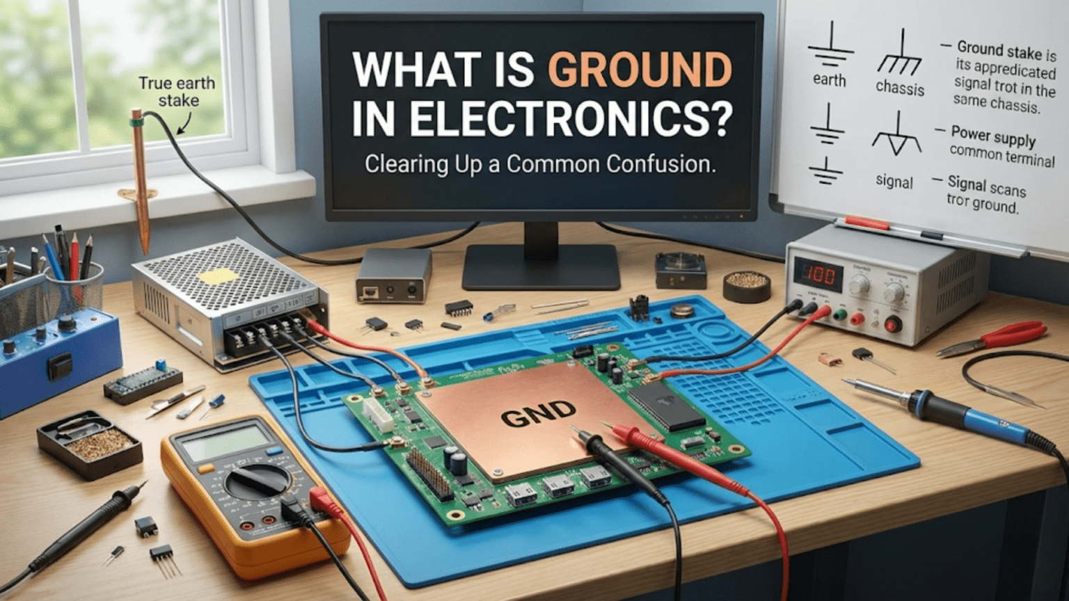
The most common ground symbol shows one horizontal line with two or three progressively shorter lines below it, resembling an inverted Christmas tree or a simplified earth symbol. This typically represents circuit ground or signal ground—the 0V reference for the circuit. All points marked with this symbol electrically connect together even though no wire is explicitly drawn between them.
This implicit connection convention reduces schematic clutter enormously. Without it, dozens or hundreds of wires would converge at the ground point, creating incomprehensible schematics. The convention that all instances of a ground symbol represent electrical connection to the same point makes schematics readable while accurately representing circuit connections.
Earth Ground Symbol
Earth ground specifically uses a symbol showing three horizontal lines of decreasing length, explicitly representing connection to earth. This appears in AC-powered equipment schematics where safety earth connection matters. Seeing this symbol indicates the connection must go to protective earth, not just to a circuit reference point.
Not all equipment grounds connect to earth ground—battery-powered devices typically do not. Distinguishing earth ground from circuit ground symbols helps clarify whether a connection goes to safety earth or merely to the circuit reference.
Chassis Ground Symbol
Chassis ground may be represented by a specific symbol (often a circle with ground lines) indicating connection to the equipment chassis or enclosure. In some equipment, chassis ground and earth ground are the same (chassis connects to earth). In other equipment, they are isolated. The schematic symbol should clarify this, though not all schematics consistently distinguish chassis from earth ground.
When working with equipment, verify whether chassis ground connects to earth ground by measuring resistance between them. If connected, resistance should be very low (less than one ohm). If isolated, resistance will be very high (megohms) or will show resistance of an intentional isolation resistor.
Analog and Digital Ground Symbols
Some schematics use distinct symbols for analog ground (AGND) and digital ground (DGND), indicating these grounds should maintain separation except at their connection point. Text labels alongside standard ground symbols may serve the same purpose. These distinctions guide layout to minimize noise coupling between analog and digital sections.
Even when schematics do not distinguish ground types, understanding that noise-sensitive analog circuits benefit from separate grounds helps guide implementation. The schematic might simply show “ground” but implementation should consider whether separate analog and digital grounds improve performance.
Measuring and Testing Ground Connections
Verifying ground integrity is essential for troubleshooting circuits and ensuring proper operation.
Resistance Measurement
Measuring resistance between ground points that should be connected verifies ground integrity. Zero or very low resistance (less than one ohm) indicates good connection. Higher resistance suggests poor connection, corrosion, or broken conductors. This simple measurement catches many grounding problems.
When measuring ground resistance, ensure the meter can measure very low resistances accurately. Many multimeters have resolution of only one ohm, inadequate for detecting a 0.5-ohm ground connection problem. Four-wire measurement techniques or specialized low-resistance ohmmeters provide better accuracy for critical measurements.
Voltage Measurement Under Load
Measuring voltage between ground points while circuits operate reveals problems invisible to resistance measurement alone. If supposedly equal ground points differ by tens or hundreds of millivolts during operation, shared ground impedance is causing voltage drops. Identifying these voltage differences guides grounding improvements.
The voltage differences often correlate with current flow. When high-current loads activate, ground voltage differences appear or increase. This correlation confirms that ground impedance is the problem and suggests where to reduce impedance or separate current paths.
Oscilloscope Observation
An oscilloscope reveals ground noise invisible to a multimeter. Connect the oscilloscope probe ground to one ground point and the probe tip to another supposedly identical ground point. Any voltage displayed indicates ground potential differences. AC-coupling the oscilloscope input removes DC offsets and amplifies the display, revealing even small AC noise voltages.
High-frequency noise on ground connections often appears only on an oscilloscope—multimeters respond too slowly to measure it. This noise can cause circuit malfunction despite low resistance ground connections, revealing that ground impedance at high frequencies exceeds acceptable limits.
Ground in Different Circuit Types
Different circuit categories have specific grounding requirements reflecting their particular characteristics and sensitivities.
Digital Circuit Grounding
Digital circuits create significant ground noise through simultaneous switching of many transistors. Multiple logic gates switching together create current spikes in ground connections. If ground impedance is excessive, these spikes create voltage variations (ground bounce) that can cause false triggering in other circuits sharing the ground.
Decoupling capacitors near integrated circuits provide local current sources for switching transients, reducing current through ground connections. Ground planes provide low-impedance return paths that minimize voltage variations. Proper grounding in digital circuits emphasizes low impedance, particularly at high frequencies where switching transients create problems.
Analog Circuit Grounding
Analog circuits, especially those processing small signals, suffer from ground noise that digital circuits tolerate easily. A few millivolts of ground noise might be insignificant to digital logic but completely overwhelm a microvolt-level sensor signal. Analog grounding emphasizes isolation from noise sources and stable voltage reference.
Star grounding separates analog signal grounds from noisy digital grounds. Careful trace routing ensures high-current grounds do not share paths with sensitive signal grounds. Input circuits connect to ground at the point nearest the input connector, minimizing ground current from internal circuits flowing through input grounds. These techniques maintain the quiet, stable grounds analog circuits require.
RF Circuit Grounding
RF circuits operating at radio frequencies face grounding challenges from the wavelength of signals approaching or exceeding circuit dimensions. At 100 MHz, wavelength is 3 meters—comparable to circuit board dimensions. At these frequencies, even short ground connections have significant inductance that impedes current flow and creates voltage variations.
RF grounding uses ground planes providing uniform, low-inductance reference. Multiple vias connect ground plane to circuit ground at many points, ensuring no point is more than a small fraction of wavelength from ground connection. Shields connect to ground at multiple points to ensure effective shielding despite frequency-dependent ground impedance.
Power Electronics Grounding
Power converters, motor drives, and other high-power circuits create large current variations in ground connections. Proper grounding must handle these currents without excessive voltage drop while preventing noise from coupling into control circuits. This often requires separate power grounds (carrying high current) and signal grounds (providing clean reference for control circuits).
The power and signal grounds connect at the power supply, preventing ground loops while isolating noise. Wide traces or heavy wires carry power ground currents with minimal resistance. Star grounding prevents power ground current from flowing through signal ground paths. These techniques maintain signal integrity despite high power ground currents.
Conclusion: Ground as Foundation
Ground serves as the foundation upon which all circuit voltages build—literally the zero point from which we measure all other potentials. While the concept seems simple, the various types of ground, the implications of ground impedance, the problems from improper grounding, and the techniques for achieving proper grounding reveal substantial complexity beneath the surface simplicity.
Understanding ground thoroughly transforms circuits from mysterious assemblies into comprehensible systems. When you recognize that ground provides both voltage reference and current return path, you understand why ground impedance matters. When you distinguish earth ground from circuit ground, you comprehend safety grounding requirements. When you appreciate how ground current creates voltage drops, you understand ground bounce and the need for low-impedance ground connections. This knowledge enables proper circuit design and effective troubleshooting.
Common grounding mistakes—ground loops, long ground connections, shared paths between high and low current circuits, floating grounds—cause countless circuit problems. Recognizing these errors and understanding their solutions—star grounding, ground planes, single-point or multi-point grounding as appropriate, isolated grounds—enables you to avoid these problems and fix them when they occur in existing circuits.
Every circuit has ground, whether explicitly shown or implicitly present. Every voltage measurement assumes a ground reference. Every current flowing into a circuit must return through ground. This fundamental role makes grounding essential knowledge for anyone working with electronics. Proper grounding ensures safety, maintains stable voltage references, minimizes noise and interference, and enables reliable circuit operation. Poor grounding creates hazards, degrades performance, and causes mysterious malfunctions.
As you design circuits, analyze schematics, and troubleshoot problems, always consider grounding carefully. Where does current return? What impedance exists in ground paths? Could shared grounds couple noise between circuits? Is earth ground required for safety? These questions guide proper grounding implementation that prevents problems before they occur.
Ground is simultaneously the simplest concept in electronics—a wire connected to the reference point—and one of the most nuanced, with different types, conflicting requirements, and subtle implementation details that separate working circuits from failing ones. Master grounding, and you have established the foundation for reliable, safe, high-performance circuit design. Neglect grounding, and even sophisticated circuits fail in mysterious, frustrating ways. The choice is clear: understand ground thoroughly, implement it correctly, and build circuits that work reliably on the solid foundation of proper grounding.