Pull-up and pull-down resistors are resistors connected to a digital signal line to force it to a defined logic level (HIGH or LOW) when no other device is actively driving it. A pull-up resistor connects the signal line to the positive supply voltage (VCC), ensuring the line reads HIGH by default; a pull-down resistor connects it to ground (GND), ensuring the line reads LOW by default. Without these resistors, an undriven digital input “floats” at an undefined voltage somewhere between HIGH and LOW, causing unpredictable behavior—randomly reading as either logic state and making circuits behave erratically.
Introduction: The Problem of Undefined States
Digital electronics operates on a fundamental assumption: every signal is either HIGH (logic 1) or LOW (logic 0). A microcontroller pin reading a button input should be definitively HIGH when the button is released and definitively LOW when pressed—or vice versa. A microcontroller reading a sensor output should know with certainty whether it’s seeing a 1 or a 0.
But what happens when no device is actively driving a signal line? What voltage does a wire sit at when nothing is pushing current into it or pulling current out? The disturbing answer is: whatever voltage it happens to pick up. An undriven wire in a real circuit is an antenna for electrical noise, drifting unpredictably in response to nearby electric fields, capacitive coupling from adjacent signals, radio frequency interference, and even the thermal noise of the wire itself. This state is called “floating,” and a floating digital input is one of the most common causes of mysterious, intermittent behavior in beginner (and experienced) electronics projects.
Pull-up and pull-down resistors solve this problem elegantly. By connecting a resistor between the signal line and a known voltage (VCC for pull-up, GND for pull-down), the resistor gently holds the signal at a defined level whenever nothing else is actively driving it. The resistor is weak enough that any active device (a microcontroller output, a button connecting to the other supply rail) can easily override it, but strong enough to prevent the line from floating.
Understanding pull-up and pull-down resistors is not a deep arcane topic—once the underlying logic is clear, these circuits are simple and their application becomes second nature. But this simplicity belies their importance. Pull-up and pull-down resistors appear in virtually every microcontroller project, every digital circuit, every communication interface, and nearly every piece of modern electronics. They’re so fundamental that many microcontrollers include them built into the silicon itself, configurable with a single line of code.
This comprehensive guide explores pull-up and pull-down resistors completely. We’ll start from the problem they solve—the floating input—examine the physics of why undefined states are dangerous, learn exactly how these resistors work, understand how to choose the right value for different applications, explore where they appear in real circuits, investigate internal pull-ups in microcontrollers, and develop the practical design instincts that make working with digital logic confident and reliable.
The Floating Input Problem
What “Floating” Means
A digital input pin is “floating” (also called “tri-state,” “high-impedance,” or “Hi-Z”) when no voltage source is actively connected to it. The pin’s voltage is not determined by any deliberate circuit element—it’s determined by whatever noise and interference the wire picks up from its environment.
Why inputs float: Digital logic inputs have very high impedance. A typical microcontroller GPIO (General Purpose Input/Output) pin configured as an input draws only a few nanoamps of current. This near-infinite impedance means:
- Tiny amounts of charge (from touching the pin, from nearby electric fields, from RF interference) cause large voltage swings
- The pin voltage is entirely at the mercy of environmental factors
- There is no restoring force bringing the voltage to any defined level
What happens electrically: The input pin, the trace connecting to it, and any wire in the circuit form a small capacitor with the surrounding environment. Charge accumulates on this capacitor from noise sources. With nothing to discharge this capacitor to a defined potential, the voltage drifts wherever the noise takes it.
Why Floating Inputs Cause Problems
Unpredictable logic readings: If a microcontroller reads a floating pin that’s supposed to detect a button press, the pin may read HIGH sometimes and LOW other times—entirely without the button being pressed. The program receives phantom button presses, misses real presses, or behaves erratically in ways that seem random.
Current consumption: A CMOS digital input floating near the threshold voltage (halfway between HIGH and LOW) draws significantly more current than one held firmly at either rail. Input stages begin to act as linear amplifiers rather than switching elements, potentially increasing device power consumption dramatically and generating heat.
Oscillation: A floating input connected to logic that feeds back to its own output can oscillate at unpredictable frequencies, consuming power and potentially causing interference.
Latch-up risk: In some CMOS processes, input voltages outside the defined HIGH/LOW ranges can trigger latch-up—a destructive parasitic thyristor structure that creates a permanent low-impedance path between VCC and GND, destroying the IC.
Demonstrating the Problem
The classic demonstration of floating inputs:
- Connect a microcontroller GPIO pin to an LED driver circuit
- Configure the pin as an input
- Leave the pin unconnected (floating)
- Power the circuit
Result: The LED will flicker randomly, turn on and off without any input, or stay stuck in one state then suddenly change. The behavior will differ between individual boards, change when you bring your hand near the circuit, and may even depend on whether you’re holding the board or it’s sitting on a table. This is not a software bug—it’s the floating input behaving exactly as physics dictates.
Pull-Up Resistors: Forcing the Default HIGH State
The Pull-Up Circuit
A pull-up resistor connects the signal line to the positive supply voltage (VCC) through a resistor:
VCC
 |
[R_pull-up]
 |
Signal Line -----> GPIO Input Pin
 |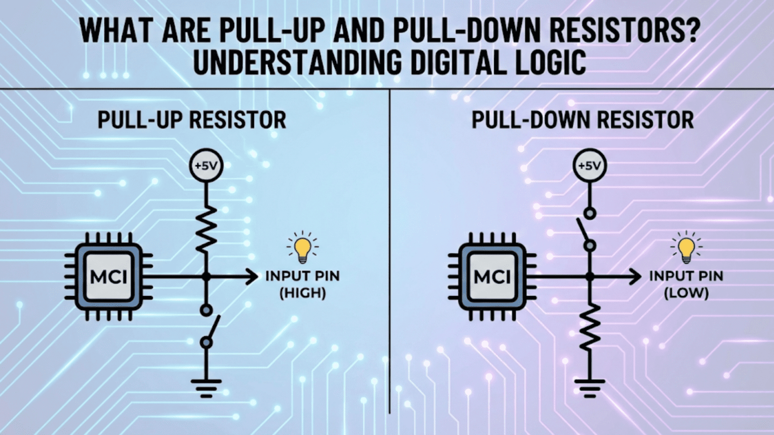
[Active device, e.g., button to GND]Default state (nothing driving the line): When no active device drives the signal line, current flows from VCC through the pull-up resistor to the GPIO input. The GPIO input draws near-zero current (it’s high impedance), so essentially no current flows—the voltage on the signal line equals VCC. The pin reads HIGH.
Active state (device drives line LOW): When a button is pressed (connecting signal line to GND), or an open-drain output pulls low, current flows from VCC through the pull-up resistor to GND through the active element. The voltage on the signal line drops to near GND (or exactly GND for ideal switch). The pin reads LOW.
The key insight: The pull-up resistor provides a weak connection to VCC. Any active device can easily override this weak pull to drive the line LOW. But when nothing is driving, the pull-up wins and the line stays HIGH.
Pull-Up with a Button
The most common pull-up application:
VCC
 |
[10kΩ]
 |
+---------> GPIO Input (default: reads HIGH)
 |
[Button]
 |
GNDButton released: GPIO reads HIGH (VCC through 10kΩ) Button pressed: GPIO reads LOW (GND through button)
Logic: The button press produces a HIGH-to-LOW transition. In software, a falling edge or LOW reading indicates button press. This is called active-low button logic because the active condition (button pressed) produces a LOW.
Current when button is pressed: With 10kΩ pull-up at 5V: I = 5V / 10kΩ = 0.5mA With 10kΩ pull-up at 3.3V: I = 3.3V / 10kΩ = 0.33mA
This small current causes no harm to the button contacts and wastes negligible power.
Why Active-Low Logic is Common
Active-low logic (signal active when LOW) dominated early digital design and remains common today for historical and practical reasons:
Historical reason: Early TTL (Transistor-Transistor Logic) transistors could sink current (pull low) more strongly than they could source current (pull high). Open-collector and open-drain outputs naturally pull low. Pull-up resistors completed these circuits.
Noise immunity reason: In noisy environments, a brief noise spike on a HIGH line is less likely to cause a false LOW (active) trigger than if logic were active-high. The line must stay LOW for a sustained period for the active condition to be detected.
Hardware reason: Many microcontroller resets, chip selects, and enable pins are active-low (indicated with a bar over the name: /RESET, /CS, /EN) because the pull-up naturally keeps them inactive (HIGH = not reset, not selected, disabled), requiring positive action (pulling LOW) to activate.
Pull-Down Resistors: Forcing the Default LOW State
The Pull-Down Circuit
A pull-down resistor connects the signal line to GND through a resistor:
[Active device, e.g., button to VCC]
 |
Signal Line -----> GPIO Input Pin
 |
[R_pull-down]
 |
GNDDefault state (nothing driving the line): When no active device drives the signal line, current would flow from the signal line through the pull-down to GND, but with nothing providing current, the pin simply sits at GND potential. The pin reads LOW.
Active state (device drives line HIGH): When a button is pressed (connecting signal line to VCC), current flows from VCC through the button, into the signal line, and splits between the GPIO input (near-zero) and through the pull-down resistor to GND. The voltage on the signal line rises to near VCC. The pin reads HIGH.
The key insight: The pull-down resistor provides a weak connection to GND. Any active device can override this weak pull to drive the line HIGH. When nothing drives, the pull-down wins and the line stays LOW.
Pull-Down with a Button
VCC
 |
[Button]
 |
+---------> GPIO Input (default: reads LOW)
 |
[10kΩ]
 |
GNDButton released: GPIO reads LOW (GND through 10kΩ) Button pressed: GPIO reads HIGH (VCC through button)
Logic: Button press produces a LOW-to-HIGH transition. HIGH reading indicates button pressed. This is active-high button logic.
When to Choose Pull-Up vs. Pull-Down
The choice between pull-up and pull-down depends on:
Active logic polarity preference:
- Active-low preferred: Use pull-up
- Active-high preferred: Use pull-down
- No preference: Either works; pull-up is more traditional
Open-drain/open-collector outputs: Open-drain and open-collector outputs can only pull LOW—they cannot drive HIGH. These outputs require pull-up resistors. Pull-down resistors don’t work with these output types.
Communication protocols:
- I²C: Requires pull-ups (open-drain bus)
- UART TX: No pull-up/pull-down needed (actively driven both HIGH and LOW)
- SPI: Varies by signal; CS/SS usually pull-up
- 1-Wire: Pull-up required
Noise environment: In high-noise environments, pull-ups (active-low) may provide better noise immunity for certain signal types.
Available internal pull-up/down: Most microcontrollers have internal pull-ups; fewer have pull-downs. If internal resistors are preferred for component count reduction, pull-up may be forced.
Choosing the Right Resistor Value
The Fundamental Trade-Off
Pull-up and pull-down resistor values involve a direct trade-off between two competing concerns:
Too high resistance (weak pull):
- Very low current consumption (good for power)
- Signal line transitions slowly from active state back to default (slow edge)
- Susceptible to noise (small interference current creates relatively large voltage change)
- May not reliably pull the line to the correct logic level against leakage currents
Too low resistance (strong pull):
- Higher current consumption (bad for power)
- Active devices must sink or source more current when driving against the pull
- Fast edge restoration
- Better noise immunity
The 10kΩ Starting Point
10kΩ is the classic general-purpose pull-up/pull-down value. It’s used for the majority of digital signal pulls in low-to-moderate speed applications.
Why 10kΩ works well: At 5V: I = 0.5mA (negligible power, easy for any active device to override) At 3.3V: I = 0.33mA (equally negligible)
10kΩ provides a comfortable balance—strong enough to reliably hold the line and provide noise immunity, weak enough to not burden any reasonable active driver.
Where 10kΩ is appropriate:
- Button/switch inputs
- Slow GPIO signals
- Open-drain outputs at low speed
- Reset lines
- Enable/disable pins
- Chip select lines at moderate speed
Calculating the Minimum Value (Maximum Pull Strength)
The pull resistor must not exceed the current-sinking capability of the driving device:
For an open-drain output: If the output can sink maximum I_sink (mA), the pull-up must not force more current than this: R_min = VCC / I_sink
Example: Open-drain output rated 16mA maximum, 5V supply: R_min = 5V / 16mA = 312.5Ω → Use 330Ω minimum
For most microcontroller GPIO open-drain outputs rated at 8–25mA, the minimum pull-up value is typically in the 200–680Ω range.
Calculating the Maximum Value (Minimum Pull Strength)
The pull resistor must be strong enough to overcome leakage currents and bring the line to a valid logic level within the required time:
For leakage current: If a device has maximum input leakage current I_leak: V_error = I_leak × R_pull
To keep voltage error below 10% of logic swing: R_max = 0.1 × VCC / I_leak
For speed requirements: The pull resistor and line capacitance form an RC time constant: τ = R_pull × C_line
For a signal to transition to valid logic level within time t_rise: R_max = t_rise / (2.2 × C_line) [for 10–90% rise time]
Example: I²C bus with 400pF maximum line capacitance, 400kHz (2.5μs period), valid logic at 70% of VCC: Rise time budget: ~0.3 × 2.5μs = 750ns R_max = 750ns / (2.2 × 400pF) ≈ 852Ω
This is why I²C recommends values around 1kΩ–4.7kΩ rather than 10kΩ for 400kHz fast mode.
Resistor Values for Common Applications
| Application | Typical Value | Reasoning |
|---|---|---|
| Button/switch input | 10kΩ | Low speed, minimal current |
| I²C (100kHz standard mode) | 4.7kΩ | Moderate speed RC time constant |
| I²C (400kHz fast mode) | 2.2kΩ–4.7kΩ | Faster edges needed |
| I²C (1MHz fast-plus) | 1kΩ–2kΩ | Fast edges required |
| SPI signals | 10kΩ (often none needed) | Active push-pull outputs |
| RESET pin | 10kΩ | Slow, non-critical speed |
| Open-drain output at speed | 1kΩ–10kΩ | Speed-dependent |
| Chip select (SPI CS) | 10kΩ | Keep unselected in idle |
| MOSFET gate drive | 10kΩ–100kΩ | Keep gate defined, high Z |
| 1-Wire bus | 4.7kΩ | Protocol specification |
| LED anode (active-low) | N/A (series resistor instead) | Current limiting, not pull |
Internal Pull-Up Resistors in Microcontrollers
What Internal Pull-Ups Are
Most modern microcontrollers include integrated pull-up resistors connected to every GPIO pin that can be enabled or disabled through software configuration registers. Some microcontrollers also offer internal pull-down resistors.
Internal pull-up characteristics:
- Resistance: Typically 20kΩ–50kΩ (varies by manufacturer and device)
- Enabled per-pin via software configuration
- Disabled by default on most microcontrollers
- Cannot be changed by hardware—software controlled
Configuring Internal Pull-Ups
Arduino/AVR microcontrollers: The ATmega series (used in Arduino Uno, Nano) has internal pull-ups of approximately 20–50kΩ.
// Enable internal pull-up on pin 2
pinMode(2, INPUT_PULLUP);

// Reading with internal pull-up: button connected between pin and GND
// buttonState = LOW when button pressed, HIGH when released
int buttonState = digitalRead(2);ARM Cortex-M (STM32, nRF52, RP2040): Most ARM-based MCUs support both pull-up and pull-down configuration:
// STM32 HAL example
GPIO_InitStruct.Pin = GPIO_PIN_0;
GPIO_InitStruct.Mode = GPIO_MODE_INPUT;
GPIO_InitStruct.Pull = GPIO_PULLUP;  // or GPIO_PULLDOWN or GPIO_NOPULL
HAL_GPIO_Init(GPIOA, &GPIO_InitStruct);Raspberry Pi Pico (RP2040) with MicroPython:
from machine import Pin
button = Pin(15, Pin.IN, Pin.PULL_UP)
# button.value() returns 0 (False) when pressed (active-low)ESP32:
// Arduino framework
pinMode(15, INPUT_PULLUP);
// or INPUT_PULLDOWN for pull-downWhen to Use Internal vs. External Pull-Ups
Use internal pull-ups when:
- Minimizing component count (simpler PCB, lower cost)
- Signal is not speed-critical
- Higher resistance (20–50kΩ) is acceptable
- The application is straightforward button/switch detection
- Prototyping where simplicity is valued
Use external pull-ups when:
- Specific resistance value is required (I²C, 1-Wire protocol requirements)
- Lower resistance needed for speed (faster edges)
- Multiple devices share an open-drain bus (I²C with multiple masters/slaves)
- The internal pull-up value is too high for reliable operation
- Power consumption with pull-up continuously energized is a concern
- The signal must be defined even before the microcontroller initializes
Important caveat: Internal pull-ups are only enabled when the microcontroller is powered and configured. During power-up, reset, and any state where the MCU hasn’t yet configured the GPIO, the internal pull-up is not active. For signals that must be defined at all times—including during power-up—use external pull-up resistors.
Pull-Up Resistors in Communication Protocols
I²C: The Open-Drain Bus
I²C (Inter-Integrated Circuit) is a two-wire serial communication protocol where both the SDA (data) and SCL (clock) lines are open-drain. This means:
- All devices on the I²C bus can only pull the lines LOW
- No device actively drives HIGH
- Pull-up resistors to VCC hold lines HIGH when no device is pulling low
Why open-drain for I²C: Open-drain allows multiple devices to share the bus without conflict. If two devices simultaneously try to communicate, one pulls LOW and the other can detect this. The protocol uses this property for bus arbitration and clock stretching.
I²C pull-up requirements:
- Standard mode (100kHz): 4.7kΩ typical (can use up to ~10kΩ)
- Fast mode (400kHz): 2.2kΩ–4.7kΩ
- Fast-plus mode (1MHz): 1kΩ–2kΩ
Common mistake: Using 10kΩ pull-ups with 400kHz I²C and experiencing communication errors. The RC time constant is too slow—the bus doesn’t rise fast enough between clock edges.
Multiple devices on I²C: Multiple devices are all connected to the same SDA and SCL lines. Each device’s pull-up contributes to the total pull-up strength (they’re in parallel). More devices → lower equivalent pull-up resistance → stronger pull → faster edges. Account for this when choosing values.
1-Wire Protocol
Dallas/Maxim’s 1-Wire protocol uses a single wire for both communication and power. The protocol requires a pull-up resistor of approximately 4.7kΩ.
Why: 1-Wire devices are powered by the parasitic power from the signal line. The pull-up provides the resting current that charges the device’s internal capacitor. Correct value is important for proper parasitic powering.
Application: DS18B20 temperature sensors, iButton devices.
Arduino example:
#include <OneWire.h>
// 4.7kΩ external pull-up required on the OneWire pin
OneWire ds(10); // on pin 10SPI (Serial Peripheral Interface)
SPI uses active push-pull drivers (actively driven both HIGH and LOW), so signal lines don’t float during communication. However:
SPI CS (Chip Select) lines: Each SPI device has a CS line, typically active-low (/CS). A pull-up holds /CS HIGH (device not selected) when the master isn’t actively driving it. Without the pull-up, the CS line floats when the bus is idle, potentially causing false selections.
Pull-up value: 10kΩ is typical for SPI CS lines. Speed is not critical here.
UART
UART TX lines are actively driven and don’t require pull-ups during normal operation. However:
Idle state: UART idles HIGH (mark state). If a UART TX output is an open-drain type (uncommon), a pull-up is needed. If push-pull (typical), no pull-up required.
RS-232 interface: Different voltage levels and logic; pull-up/down resistors may be needed at interface boundaries.
Practical Design Scenarios
Scenario 1: Reliable Button Detection on Arduino
Problem: Button presses are randomly detected even without pressing.
Root cause: Button pin is floating.
Solution with internal pull-up:
void setup() {
    pinMode(2, INPUT_PULLUP);  // Enable internal pull-up
    Serial.begin(9600);
}

void loop() {
    int buttonState = digitalRead(2);
    if (buttonState == LOW) {  // LOW = button pressed (active-low)
        Serial.println("Button pressed!");
    }
}Hardware: Button connected from pin 2 to GND. No external components needed.
Solution with external pull-up (more reliable for production): Add 10kΩ resistor from pin 2 to VCC on the PCB. Button connects pin to GND.
Scenario 2: Adding I²C Sensor to Raspberry Pi Pico
Problem: Connecting a BME280 environmental sensor via I²C. Communication works intermittently.
Investigation: I²C pull-ups missing or wrong value.
Solution: RP2040 has internal I²C pull-ups of about 50kΩ—too high for reliable 400kHz communication.
Add external 4.7kΩ pull-ups:
- SDA line: 4.7kΩ to 3.3V
- SCL line: 4.7kΩ to 3.3V
Calculation verification: 400pF max bus capacitance, 400kHz: Maximum R = 750ns / (2.2 × 400pF) ≈ 852Ω (that’s the maximum for 400kHz)
Wait—4.7kΩ exceeds this? With a single device and short traces, actual capacitance is much less than 400pF maximum. For a single sensor on a short bus, 4.7kΩ typically works well at 400kHz. For maximum reliability with multiple devices or long traces, use 2.2kΩ.
Scenario 3: MOSFET Gate Pull-Down
Problem: MOSFET gate is left floating during microcontroller reset. Power-on transients turn MOSFET on unexpectedly, potentially damaging the load.
Solution: Add 100kΩ pull-down from MOSFET gate to GND.
MCU GPIO Output Pin ----[Gate Resistor 100Ω]---+---- MOSFET Gate
                                                |
                                             [100kΩ]
                                                |
GNDWhy 100kΩ: MOSFET gates have very high impedance. Even a 100kΩ pull-down easily holds the gate LOW when the MCU isn’t driving it. The gate resistor (100Ω) limits gate charging current without impeding the pull-down.
Scenario 4: Multiple Push Buttons with Minimal Pins
Problem: 8 buttons needed on a microcontroller with limited GPIO pins.
Solution using active-low with internal pull-ups: Each button connects one GPIO to GND. 8 buttons use 8 GPIO pins, all configured INPUT_PULLUP.
Scanning in code:
int buttonPins[] = {2, 3, 4, 5, 6, 7, 8, 9};

void setup() {
    for (int i = 0; i < 8; i++) {
        pinMode(buttonPins[i], INPUT_PULLUP);
    }
}

void loop() {
    for (int i = 0; i < 8; i++) {
        if (digitalRead(buttonPins[i]) == LOW) {
            // Button i is pressed
        }
    }
}Scenario 5: Open-Drain Output from Sensor
Problem: Temperature sensor has open-drain alert output. Alert line doesn’t drive HIGH.
Context: Open-drain outputs can only pull LOW—they cannot source current to drive HIGH. An open-drain output with no pull-up leaves the line floating when the output is inactive (not alerting).
Solution: Add pull-up resistor:
VCC (3.3V)
    |
 [10kΩ]
    |
 Alert Line -----> GPIO Input Pin
    |
[Open-drain from sensor]
    |
GNDWhen sensor alerts: Line pulled LOW by sensor → reads LOW at GPIO When no alert: Pull-up holds line HIGH → reads HIGH at GPIO
Comparison Table: Pull-Up vs. Pull-Down at a Glance
| Characteristic | Pull-Up Resistor | Pull-Down Resistor |
|---|---|---|
| Connects signal to | VCC (positive supply) | GND (negative supply / ground) |
| Default state | HIGH (logic 1) | LOW (logic 0) |
| Active state | LOW (logic 0) | HIGH (logic 1) |
| Logic convention | Active-LOW | Active-HIGH |
| Required for open-drain | Yes — essential | No — incompatible |
| Common bus use | I²C SDA/SCL, 1-Wire | Less common on shared buses |
| Typical value | 4.7kΩ–10kΩ | 10kΩ |
| Internal MCU support | Very common | Less common |
| Historical preference | Very common (TTL era) | Less traditional |
| RESET pin convention | Standard (active-LOW reset) | Rare |
| Button wiring | Button to GND | Button to VCC |
| Indicator in schematics | Resistor to VCC/positive rail | Resistor to GND symbol |
| Effect when disabled MCU | Defined (VCC through resistor) | Defined (GND through resistor) |
| Current when active | Flows from VCC through R to GND | Flows from VCC through device to R |
Common Mistakes and How to Avoid Them
Mistake 1: Forgetting Pull-Up/Down on Open-Drain Outputs
Symptom: Signal stays LOW permanently, never goes HIGH; or signal floats and behaves erratically.
Cause: Open-drain output has no pull-up to bring line HIGH when output is off.
Prevention: Whenever using an open-drain or open-collector output, always ask: “What holds this line HIGH when the output isn’t pulling low?” If nothing — add a pull-up.
Mistake 2: Wrong Value for I²C Speed
Symptom: I²C works at low speed (100kHz) but fails at high speed (400kHz); communication errors increase with more devices on bus.
Cause: Pull-up resistance too high for required signal edges at the target speed.
Prevention: Calculate RC time constant for your bus capacitance and target frequency. For 400kHz with any significant bus capacitance, use 2.2kΩ–4.7kΩ, not 10kΩ.
Mistake 3: Relying on Internal Pull-Ups During Power-Up
Symptom: Circuit behaves unexpectedly during power-up or reset; relay or motor activates briefly at startup.
Cause: Internal pull-ups only enabled after MCU initializes GPIO—during reset and early boot, pins are high-impedance with no pull.
Prevention: Use external pull-up or pull-down resistors for any signal that must be defined before the MCU completes initialization.
Mistake 4: Conflicting Drivers on Pull-Up Bus
Symptom: Pull-up line always reads LOW regardless of intended state; entire bus stuck.
Cause: One device is permanently driving the line LOW (shorted output, misconfigured GPIO, damaged device).
Prevention: Ensure all devices sharing a pull-up bus use open-drain outputs only. Never mix push-pull and open-drain outputs on the same pull-up line.
Mistake 5: Pull-Up on Push-Pull Output
Symptom: Device driving HIGH works fine; device trying to drive LOW must fight the pull-up, drawing excessive current, heating the driver, and potentially not reaching valid LOW voltage.
Cause: Pull-up resistor added to a signal already driven by a push-pull output.
Prevention: Pull-up and pull-down resistors are only needed when a signal can be undriven (floating) or when open-drain outputs are used. Push-pull outputs don’t need pull resistors on the same line.
Conclusion: The Quiet Foundation of Digital Reliability
Pull-up and pull-down resistors are among the most unglamorous components in electronics—a single resistor, a simple connection, a trivial concept. Yet their presence or absence can determine whether a digital circuit functions reliably or behaves with maddening unpredictability. They represent the physical solution to a fundamental problem in digital electronics: the undefined state.
Core Principles to Remember
Every undriven digital input must be defined. If a signal line can ever be in a state where no device is actively driving it, that line must have a pull-up or pull-down resistor to prevent it from floating.
Pull-ups for open-drain; either for switch inputs. Open-drain and open-collector outputs require pull-up resistors—they can only pull LOW, never HIGH. Switch inputs can use either pull-up (active-low) or pull-down (active-high) based on preference and convention.
10kΩ is a reliable general-purpose starting point. For most non-speed-critical applications, 10kΩ provides a good balance between current consumption and signal integrity. Adjust downward for higher-speed signals or open-drain buses.
Protocol-specific values matter. I²C, 1-Wire, and other open-drain protocols have specific pull-up requirements derived from timing and electrical constraints. Don’t use arbitrary values for these—follow the specification.
Internal pull-ups are convenient but limited. Available in most microcontrollers, internal pull-ups simplify prototyping but have higher resistance than external options and aren’t active during MCU initialization.
From Beginner to Expert
Understanding pull-up and pull-down resistors at this depth—not just “add 10kΩ to make button work” but understanding the floating problem, the physics of open-drain outputs, the speed versus current trade-off, and the protocol-specific requirements—marks a significant step in electronics maturity.
When you see a schematic with a resistor connecting a signal line to VCC or GND, you no longer wonder why it’s there. You know immediately: it defines a default state, enables open-drain communication, or prevents an uninitiated MCU pin from causing havoc at startup. That recognition, multiplied across thousands of components and circuits, builds the intuitive circuit reading ability that characterizes experienced electronics practitioners.
Pull-up and pull-down resistors: small components, simple concept, profound importance. The quiet foundation on which reliable digital logic is built.