Resistor color codes are a standardized system of colored bands printed on resistor bodies that encode the component’s resistance value and tolerance: each color represents a digit (black=0 through white=9), and reading the bands from left to right gives the significant digits, a multiplier, and a tolerance percentage—so a resistor with bands Orange, Orange, Brown, Gold reads as 3, 3, ×10 = 330Ω ±5%, one of the most common values in robotics for LED current limiting. Most resistors use either a 4-band system (two significant digits, one multiplier, one tolerance) or a 5-band system (three significant digits, one multiplier, one tolerance) for higher-precision components.
Introduction
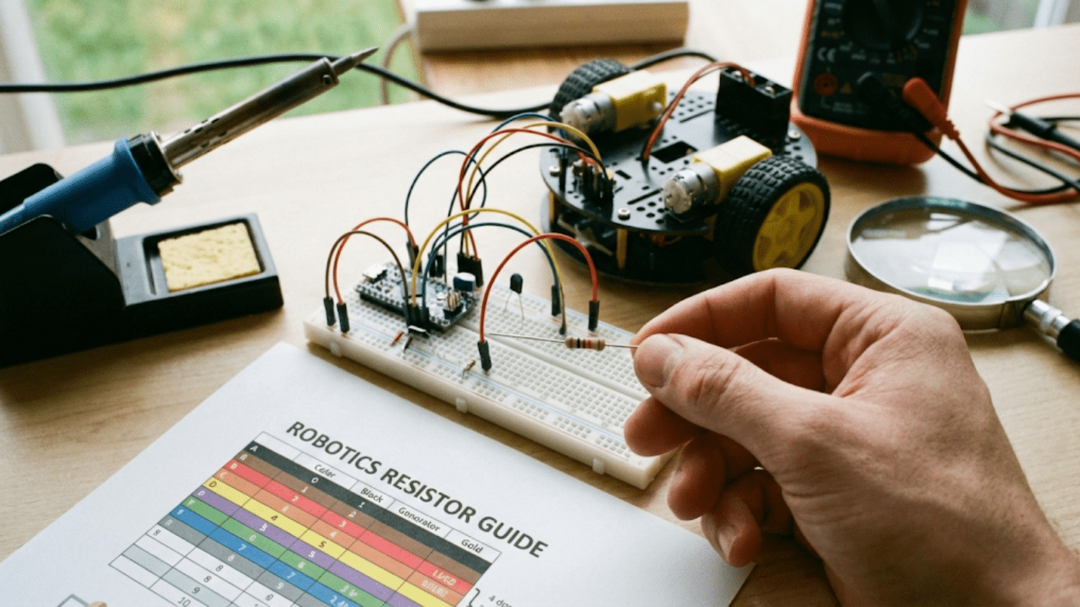
You’re sorting through a bag of resistors looking for the right value for an LED circuit. There are no labels on the components themselves — just tiny colored bands wrapped around a small cylindrical body. Without knowing how to read those bands, the resistors are indistinguishable from each other. With the color code, each one announces its value clearly in a notation you can read at a glance.
Resistors are among the most fundamental components in electronics, and they appear constantly in robotics: limiting current to LEDs and sensors, setting voltage divider ratios for battery monitoring, providing pull-up and pull-down values for digital inputs, setting gain in amplifier circuits, and protecting microcontroller pins from excessive current. They are inexpensive, passive, and deceptively simple — but using the wrong value can mean a burned-out LED, a damaged microcontroller pin, or a voltage divider that produces completely wrong readings.
Reading resistor color codes is one of those foundational skills that every robotics builder uses repeatedly, from the first project to the most sophisticated system. This article teaches you the complete system — 4-band, 5-band, and 6-band resistors; tolerance markings; preferred value series; and how to apply resistor calculations to the specific circuits you’ll build in robotics.
Why Resistors Are Marked with Color Bands
Before the color code, resistors were marked with printed numbers. This worked fine on larger components, but as electronics miniaturized, printed text became too small to read reliably, and printing ink flaked off small components during handling and installation. The color band system was developed in the 1920s and standardized by the IEC (International Electrotechnical Commission) because:
- Colors remain readable on very small components
- Colors don’t require precise printing alignment to read correctly
- Colors are legible from multiple angles
- The system is position-independent (you don’t need to find a specific face to read the component)
- Colors survive soldering temperatures and handling better than fine printed text
The same basic system has been in use for nearly a century and remains standard today, though surface-mount resistors (the tiny rectangular components used in automated PCB assembly) use a printed numeric code instead since they have a flat readable face.
The Color-to-Number Mapping: The Foundation of Everything
The entire color code system rests on a single mapping of ten colors to the digits 0 through 9. Memorizing this mapping — or having a reliable way to look it up — is the foundation of reading any resistor:
Color       Digit    Memory Aid
──────────────────────────────────────────────────────────
Black         0      B starts the alphabet → 0 starts counting
Brown         1      1 rhymes with "bun" (brown bun)
Red           2      2nd color of traffic light
Orange        3      3 rhymes with "tree" (orange tree)
Yellow        4      4 letters in "yell" (from yellow)
Green         5      5-dollar bill is sometimes called a "fin" (green)
Blue          6      6 sounds like "sex" (Blue Six)
Violet        7      7 is lucky (Violet Seven)
Gray          8      "Great" has 8 letters minus the silent ones... (tenuous)
White 9 Last color → last single digitMemory aids are personal — find ones that work for you. The most reliable mnemonics encode the sequence in a sentence where each word starts with the first letter of each color in order:
“Better Be Right Or Your Great Big Values Go Wrong”
- Better = Black (0)
- Be = Brown (1)
- Right = Red (2)
- Or = Orange (3)
- Your = Yellow (4)
- Great = Green (5)
- Big = Blue (6)
- Values = Violet (7)
- Go = Gray (8)
- Wrong = White (9)
Say this sentence a few times while looking at the color table, and most people find the mapping sticks within minutes.
The 4-Band Resistor: Standard for General Use
The 4-band color code is the most common system and the one you’ll encounter on most through-hole resistors in hobby electronics kits and robotics components.
Band Structure
      ┌─────────────────────────────────┐
      │  Band 1  Band 2  Band 3  Band 4 │
      │  [■■■]   [■■■]   [■■■]   [■■■]  │
      │  1st dig 2nd dig Multi  Toler   │
      └─────────────────────────────────┘
         ← read from left to right →
(gold/silver band is always on the right = tolerance)Band 1 — First significant digit: The first color gives the tens digit of the resistance value.
Band 2 — Second significant digit: The second color gives the units digit.
Band 3 — Multiplier: This color tells you what power of 10 to multiply the two-digit number by. The colors map to multipliers as follows:
Color     Multiplier    What it means
────────────────────────────────────────
Black     ×1            ×10⁰ = ×1
Brown     ×10           ×10¹
Red       ×100          ×10²
Orange    ×1,000        ×10³  (×1kΩ)
Yellow    ×10,000       ×10⁴  (×10kΩ)
Green     ×100,000      ×10⁵  (×100kΩ)
Blue      ×1,000,000    ×10⁶  (×1MΩ)
Violet    ×10,000,000   ×10⁷
Gold      ×0.1          ÷10   (for values < 10Ω)
Silver ×0.01 ÷100 (for values < 1Ω)Band 4 — Tolerance: This band, always the rightmost, tells you how accurately the resistor’s actual value matches its marked value:
Color     Tolerance
──────────────────
Brown     ±1%
Red       ±2%
Gold      ±5%
Silver    ±10%
(no band) ±20%Gold and silver tolerance bands are noticeably wider and spaced slightly apart from the first three bands, making them easier to identify as the tolerance band rather than a multiplier.
Reading a 4-Band Resistor: Step by Step
Step 1: Orient the resistor with the tolerance band (gold or silver) on the right.
Step 2: Read Band 1 (leftmost) → first digit.
Step 3: Read Band 2 → second digit. You now have a two-digit number.
Step 4: Read Band 3 (multiplier) → multiply the two-digit number by this value.
Step 5: Read Band 4 (tolerance) → note the accuracy range.
Worked Examples
Example 1: Brown, Black, Red, Gold
- Band 1: Brown = 1
- Band 2: Black = 0
- Band 3: Red = ×100
- Band 4: Gold = ±5%
- Value: 10 × 100 = 1,000Ω = 1kΩ ±5%
Example 2: Orange, Orange, Brown, Gold
- Band 1: Orange = 3
- Band 2: Orange = 3
- Band 3: Brown = ×10
- Band 4: Gold = ±5%
- Value: 33 × 10 = 330Ω ±5% (This is the LED current-limiting resistor for a red LED from 5V!)
Example 3: Yellow, Violet, Orange, Gold
- Band 1: Yellow = 4
- Band 2: Violet = 7
- Band 3: Orange = ×1,000
- Band 4: Gold = ±5%
- Value: 47 × 1,000 = 47,000Ω = 47kΩ ±5%
Example 4: Red, Red, Gold, Gold
- Band 1: Red = 2
- Band 2: Red = 2
- Band 3: Gold = ×0.1
- Band 4: Gold = ±5%
- Value: 22 × 0.1 = 2.2Ω ±5% (Gold multiplier indicates a sub-10Ω resistor — used for current sensing)
Example 5: Brown, Black, Green, Brown
- Band 1: Brown = 1
- Band 2: Black = 0
- Band 3: Green = ×100,000
- Band 4: Brown = ±1%
- Value: 10 × 100,000 = 1,000,000Ω = 1MΩ ±1%
The 5-Band Resistor: Higher Precision
5-band resistors follow the same principle as 4-band but add a third significant digit, allowing more precise value specification. They are common in precision applications like feedback networks, instrumentation amplifiers, and voltage dividers where exact resistance matters.
Band Structure
      ┌───────────────────────────────────────────┐
      │  Band 1  Band 2  Band 3  Band 4  Band 5   │
      │  [■■■]   [■■■]   [■■■]   [■■■]   [■■■]    │
      │  1st dig 2nd dig 3rd dig Multi  Toler     │
      └───────────────────────────────────────────┘
Bands 1–3: Three significant digits (hundreds, tens, units). Band 4: Multiplier (same color-to-multiplier mapping as 4-band). Band 5: Tolerance — but now with finer options:
Color     Tolerance
──────────────────
Brown     ±1%
Red       ±2%
Green     ±0.5%
Blue      ±0.25%
Violet    ±0.1%
Gray      ±0.05%
Gold      ±5%
Silver    ±10%
Reading a 5-Band Resistor: Worked Examples
Example 1: Brown, Black, Black, Brown, Brown
- Band 1: Brown = 1
- Band 2: Black = 0
- Band 3: Black = 0
- Band 4: Brown = ×10
- Band 5: Brown = ±1%
- Value: 100 × 10 = 1,000Ω = 1kΩ ±1%
Example 2: Red, Red, Black, Black, Brown
- Band 1: Red = 2
- Band 2: Red = 2
- Band 3: Black = 0
- Band 4: Black = ×1
- Band 5: Brown = ±1%
- Value: 220 × 1 = 220Ω ±1% (The 220Ω LED resistor for 5V systems)
Example 3: Orange, Orange, Red, Brown, Brown
- Band 1: Orange = 3
- Band 2: Orange = 3
- Band 3: Red = 2
- Band 4: Brown = ×10
- Band 5: Brown = ±1%
- Value: 332 × 10 = 3,320Ω = 3.32kΩ ±1%
Distinguishing 4-Band from 5-Band
When you pick up a resistor and count the bands, you’ll immediately know whether it’s 4-band or 5-band. However, some 5-band resistors can be confusing because the tolerance band color (brown = ±1%) is also a valid digit color. The tell-tale signs of a 5-band resistor:
- Typically has tighter spacing between bands 4 and 5 (the gap before the tolerance band is slightly larger in most 5-band resistors)
- The tolerance band in precision 5-band resistors is often brown, red, or green rather than gold or silver
- If the value doesn’t make sense as a 4-band read, try reading it as 5-band
The 6-Band Resistor: Adding Temperature Coefficient
A sixth band is occasionally added to specify the temperature coefficient (tempco) — how much the resistance changes per degree Celsius change in temperature. This matters in precision circuits where temperature stability is important. The sixth band is usually brown (100 ppm/°C), red (50 ppm/°C), yellow (25 ppm/°C), or orange (15 ppm/°C). For most robotics applications, 6-band resistors are rarely needed, but it’s useful to know they exist so you don’t mistake a 6-band for a 5-band.
Preferred Value Series: Why You Can’t Find Every Value
You might expect resistors to be available in every value from 1Ω to 10MΩ — but they’re not. Resistors are manufactured in standardized preferred value series called E-series, where only certain values exist within each decade. This isn’t a limitation of manufacturing — it’s an elegant engineering system.
The E12 and E24 Series
The most common series for general-purpose robotics resistors:
E12 series (±10% tolerance, 12 values per decade):
10, 12, 15, 18, 22, 27, 33, 39, 47, 56, 68, 82
(then ×10: 100, 120, 150, 180, 220, 270, 330, 390, 470, 560, 680, 820)
(then ×100: 1k, 1.2k, 1.5k, 1.8k, 2.2k, 2.7k, 3.3k, 3.9k, 4.7k, 5.6k, 6.8k, 8.2k)E24 series (±5% tolerance, 24 values per decade):
10, 11, 12, 13, 15, 16, 18, 20, 22, 24, 27, 30,
33, 36, 39, 43, 47, 51, 56, 62, 68, 75, 82, 91The clever property of E-series values: with ±10% tolerance, any possible resistance value falls within the tolerance range of at least one E12 value. With ±5% tolerance, any value is covered by at least one E24 value. There’s never a need for intermediate values because any desired resistance is always “close enough” to a standard value given the tolerance.
E96 and E192 for Precision
Precision resistors (±1% and tighter) use E96 (96 values per decade) or E192 (192 values per decade), providing increments of about 2.3% and 1.2% respectively. These are the series you’ll encounter in 5-band resistors.
Resistor Calculations for Common Robotics Circuits
Understanding the color code is only half the story — knowing which value to use in your circuits is equally important. Here are the most common resistor calculations in robotics:
LED Current-Limiting Resistor
Every LED needs a series resistor to limit current. Without it, an LED connected directly to a voltage source draws excessive current and burns out within seconds.
Formula:
R = (Vsupply - Vled) / Iled

Where:
  Vsupply = supply voltage (e.g., 5V)
  Vled    = LED forward voltage (check datasheet; typical values below)
  Iled    = desired LED current (typically 10–20mA for indicator LEDs)

Typical LED forward voltages:
  Red LED:           1.8–2.2V (use 2.0V)
  Yellow/Orange LED: 1.8–2.2V (use 2.0V)
  Green LED:         2.0–2.4V (use 2.1V)
  Blue LED:          3.0–3.4V (use 3.2V)
  White LED:         3.0–3.5V (use 3.2V)
  Infrared LED:      1.2–1.8V (use 1.5V)

Example: Red LED, 5V supply, 15mA desired current:
R = (5V - 2.0V) / 0.015A = 3.0V / 0.015A = 200Ω

Nearest E24 value: 200Ω (exists in E24 series)
Nearest E12 value: 220Ω (slightly less current, 13.6mA — fine)

Check power dissipation: P = I² × R = (0.015)² × 200 = 0.045W
Standard 1/4W resistor is easily sufficient.Common LED resistor quick reference:
5V supply:
Red/Yellow/Orange LED: R = (5-2.0)/0.015 = 200Ω → use 220Ω
Green LED: R = (5-2.1)/0.015 = 193Ω → use 200Ω or 220Ω
Blue/White LED: R = (5-3.2)/0.015 = 120Ω → use 120Ω or 100Ω
3.3V supply:
Red/Yellow/Orange LED: R = (3.3-2.0)/0.015 = 87Ω → use 82Ω or 100Ω
Green LED: R = (3.3-2.1)/0.015 = 80Ω → use 82Ω
Blue/White LED: R = (3.3-3.2)/0.015 = 6.7Ω → use 6.8Ω or 10Ω
(very small: blue/white LEDs need barely any drop from 3.3V)Voltage Divider for Battery Monitoring
A voltage divider uses two resistors in series to produce a fraction of the input voltage, allowing a microcontroller’s ADC (limited to 0–5V input) to measure higher voltages safely:
Voltage divider:

Vin ──── R1 ──── Vmid ──── R2 ──── GND
                  │
               (to ADC)

Vmid = Vin × R2 / (R1 + R2)

For measuring a 3S LiPo (max 12.6V) with an Arduino (ADC max 5V):
We need: Vmid / Vin ≤ 5V / 12.6V = 0.397

Choose: R2 / (R1 + R2) ≤ 0.397
Try R1 = 10kΩ, R2 = 4.7kΩ:
Ratio = 4.7 / (10 + 4.7) = 4.7 / 14.7 = 0.320

Vmid at full charge (12.6V): 12.6 × 0.320 = 4.03V → within ADC range ✓
Vmid at cutoff (9.0V):        9.0 × 0.320 = 2.88V → still readable ✓

Calibration:
ADC reading of 1023 corresponds to 5.0V at the ADC input
5.0V at ADC → 5.0 / 0.320 = 15.6V battery voltage
ADC to battery voltage: Vbatt = (ADC / 1023.0) × 5.0 / 0.320
= (ADC / 1023.0) × 15.625// Battery voltage monitoring with voltage divider
const float R1 = 10000.0; // 10kΩ (brown, black, orange, gold)
const float R2 = 4700.0; // 4.7kΩ (yellow, violet, red, gold)
const float VREF = 5.0; // ADC reference voltage
const int BATT_PIN = A0;
float readBatteryVoltage() {
int raw = analogRead(BATT_PIN);
float vmid = (raw / 1023.0) * VREF;
return vmid * (R1 + R2) / R2; // Reverse the divider equation
}Pull-Up Resistor for Digital Input
Pull-up resistors hold a digital input at a known HIGH state when no active signal is connected. The value must be high enough not to waste significant current when the pin is pulled to ground, but low enough to reliably overcome noise:
Typical pull-up resistor selection:

Signal type       Recommended range   Common value used
────────────────────────────────────────────────────────
I2C SDA/SCL       2.2kΩ – 4.7kΩ      4.7kΩ
Button/switch     10kΩ – 100kΩ       10kΩ  (good compromise)
GPIO general      4.7kΩ – 100kΩ      10kΩ
Open-collector    1kΩ – 10kΩ         4.7kΩ
Long cable runs   1kΩ – 4.7kΩ        2.2kΩ (lower impedance fights noise)
A 10kΩ pull-up with a 5V supply draws 5V/10kΩ = 0.5mA when the pin is pulled to ground — a modest but continuous current when a button is pressed. This is why pull-up values larger than 100kΩ are generally avoided: they become susceptible to noise pickup on the high-impedance input line.
Current-Sense Resistor
A current-sense resistor (shunt resistor) inserted in series with a load allows measurement of current by measuring the voltage drop across the known resistance:
Current sense:
Load current flows through Rsense → creates voltage drop → measured by ADC

Vsense = Isense × Rsense
Isense = Vsense / Rsense

Design: choose Rsense so that at maximum expected current,
Vsense stays within ADC input range (0–5V or 0–3.3V).

For measuring up to 2A with 5V ADC:
Rsense = Vmax / Imax = 3.3V / 2A = 1.65Ω → use 1.5Ω or 1.8Ω

At 2A: Vsense = 2A × 1.5Ω = 3.0V (within 0-5V range) ✓
Power in Rsense at 2A: P = I² × R = 4 × 1.5 = 6W → use 10W wirewound resistor!

For measuring up to 500mA with 5V ADC:
Rsense = 3.3V / 0.5A = 6.6Ω → use 6.8Ω standard value

At 500mA: P = (0.5)² × 6.8 = 1.7W → use 2W resistor minimumResistor Power Rating: The Other Critical Specification
Color bands tell you resistance value and tolerance, but they tell you nothing about power rating — how much heat the resistor can safely dissipate. This is separately specified and physically determined by the resistor’s size:
Standard through-hole resistor power ratings:
Package size    Power rating    Physical length    Common applications
──────────────────────────────────────────────────────────────────
1/8 W (0.125W) 125mW           ~6mm              Microcontroller circuits, signal lines
1/4 W (0.25W)  250mW           ~9mm              Most general robotics use
1/2 W (0.5W)   500mW           ~11mm             Moderate current paths
1 W             1W             ~15mm             Motor driver logic, some power paths
2 W             2W             ~20mm             Current sense in moderate-power circuits
5 W             5W             ~25mm             Higher-power sense resistors
10 W+ 10W+ 20mm+ (wirewound) Power circuits, current sensingThe 1/4W resistor is the standard for most robotics digital and signal circuits. For any resistor through which significant current flows — LED drive resistors at high current, voltage dividers connected to lower-impedance sources, current sense resistors — always verify the power dissipation:
Power check formula: P = I² × R = V² / R = V × I

Red LED resistor: R = 220Ω, I = 13.6mA
P = (0.0136)² × 220 = 0.040W = 40mW → 1/4W resistor fine

Voltage divider: R1 = 10kΩ, R2 = 4.7kΩ, Vin = 12.6V
Current through divider: I = 12.6V / (10k + 4.7k) = 0.857mA
Power in R1: P = (0.000857)² × 10000 = 7.3mW → fine
Power in R2: P = (0.000857)² × 4700 = 3.4mW → fine
Both well within 1/4W rating.

Current sense resistor: R = 0.1Ω, I = 10A (motor circuit)
P = (10)² × 0.1 = 10W → 1/4W resistor would INSTANTLY burn out!
Need: 15W+ wirewound power resistor (or use a dedicated current sensor IC)A 1/4W resistor in a 10W application will fail immediately, potentially creating a fire hazard in the robot. Always check power before finalizing resistor selection in any circuit with significant current.
Reading Resistors in Practice: Tips and Pitfalls
Tip 1: Identify the Tolerance Band First
The tolerance band (gold, silver, or in precision resistors: brown, red, green) is your anchor point. Gold and silver are easy to spot because they don’t appear in the digit sequence (they appear only as multipliers for sub-10Ω values and as tolerance bands). Identify the gold or silver band first, orient it to the right, and read left to right.
Tip 2: When In Doubt, Measure
If the bands are faded, the resistor body color is unusual (making color discrimination difficult), or you’re genuinely uncertain, use a multimeter in resistance mode. Set to an appropriate range and measure directly:
Multimeter resistance measurement:
1. Set multimeter to resistance (Ω) mode
2. Select range above the expected value (start with 20kΩ range if uncertain)
3. Touch probes to both resistor leads
4. Read value — no polarity concern (resistors are not polarized)
5. If reading is near zero: range too high, select lower range
   If reading is "OL" or "1": range too low, select higher range

Accuracy: a good multimeter measures resistance to ±1% or better
This is more accurate than reading a ±10% color-coded resistor visually.Tip 3: Color Perception Under Different Lighting
Under fluorescent lighting, orange and red can look similar; yellow and green can be difficult to distinguish; and brown and red look nearly identical. If you’re uncertain between two colors:
- Orange vs. red: Orange is distinctly warmer and more orange-tinted; red is a pure, cooler red
- Yellow vs. green: Yellow is clearly warm and bright; green has a cooler, bluish tint
- Brown vs. red: Brown is darker and muddy; red is brighter and cleaner
Natural daylight or a daylight-spectrum LED work lamp provides the best color discrimination for reading resistors.
Tip 4: SMD Resistor Codes Are Different
Surface-mount resistors use a different marking system:
- 3-digit code: Two significant digits + multiplier digit (212 = 21 × 10² = 2,100Ω = 2.1kΩ)
- 4-digit code: Three significant digits + multiplier (1002 = 100 × 10² = 10,000Ω = 10kΩ)
- EIA-96 code: A two-digit number plus a letter for E96 series values
SMD resistors are very common in commercial robots and custom PCBs, but you’re less likely to encounter them in breadboard and perfboard robotics projects.
Common Resistor Values in Robotics: A Quick Reference
These are the resistor values you’ll reach for most often in robot projects:
Value        Color Code (4-band, ±5%)              Common Use
──────────────────────────────────────────────────────────────────────────────
10Ω          Br-Bk-Bk-Gd                          Small current sense, motor brake
33Ω          Or-Or-Bk-Gd                          High-current LED drive
47Ω          Ye-Vi-Bk-Gd                          LED drive (higher brightness)
100Ω         Br-Bk-Br-Gd                          LED current limiting
220Ω         Rd-Rd-Br-Gd                          LED from 5V (standard)
330Ω         Or-Or-Br-Gd                          LED from 5V (slightly dimmer)
470Ω         Ye-Vi-Br-Gd                          LED, signal protection
1kΩ          Br-Bk-Rd-Gd                          Pull-up, signal divider
2.2kΩ        Rd-Rd-Rd-Gd                          I2C pull-up, voltage divider
4.7kΩ        Ye-Vi-Rd-Gd                          I2C pull-up (standard)
10kΩ         Br-Bk-Or-Gd                          General pull-up, voltage divider
47kΩ         Ye-Vi-Or-Gd                          High-impedance inputs, RC filters
100kΩ        Br-Bk-Ye-Gd                          High-impedance signal conditioning
1MΩ Br-Bk-Gr-Gd Very high impedance, gate pull-downThese twelve values cover the vast majority of resistor requirements in beginner and intermediate robotics. If you buy an assortment kit containing these values (plus a few others like 150Ω, 560Ω, 2kΩ, and 22kΩ), you’ll rarely need to order a specific value — most circuits can be satisfied by the nearest available value with minor current adjustment.
Resistor Color Code Quick Reference Card
╔══════════════════════════════════════════════════════════════╗
║              RESISTOR COLOR CODE REFERENCE                   ║
╠══════════╦═══════╦════════════╦══════════════════════════════╣
║ Color    ║ Digit ║ Multiplier ║ Tolerance                    ║
╠══════════╬═══════╬════════════╬══════════════════════════════╣
║ Black    ║   0   ║ ×1         ║ —                            ║
║ Brown    ║   1   ║ ×10        ║ ±1%                          ║
║ Red      ║   2   ║ ×100       ║ ±2%                          ║
║ Orange   ║   3   ║ ×1,000     ║ —                            ║
║ Yellow   ║   4   ║ ×10,000    ║ —                            ║
║ Green    ║   5   ║ ×100,000   ║ ±0.5%                        ║
║ Blue     ║   6   ║ ×1,000,000 ║ ±0.25%                       ║
║ Violet   ║   7   ║ ×10M       ║ ±0.1%                        ║
║ Gray     ║   8   ║ ×100M      ║ ±0.05%                       ║
║ White    ║   9   ║ —          ║ —                            ║
║ Gold     ║   —   ║ ×0.1       ║ ±5%                          ║
║ Silver   ║   —   ║ ×0.01      ║ ±10%                         ║
╚══════════╩═══════╩════════════╩══════════════════════════════╝

4-BAND: [digit][digit][multiplier][tolerance]
5-BAND: [digit][digit][digit][multiplier][tolerance]

Mnemonic: "Better Be Right Or Your Great Big Values Go Wrong"
           Black Brown Red Orange Yellow Green Blue Violet Gray White
0 1 2 3 4 5 6 7 8 9Summary
Resistor color codes are a compact, durable, and reliable system for encoding resistance values on small components — and reading them fluently takes only a few minutes of practice once the color-to-digit mapping is memorized. The 4-band system (two digits, multiplier, tolerance) covers most general-purpose resistors in robotics. The 5-band system adds a third significant digit for precision components. Both systems follow the same color-to-number mapping: Black through White for digits 0–9, with gold and silver serving as sub-1 multipliers and tolerance indicators.
Beyond reading the code, the practical skill is knowing which values to reach for. LED current-limiting resistors, voltage divider networks for battery monitoring, pull-up resistors for digital inputs, and current-sense resistors for power measurement are the core resistor applications in robotics — each with straightforward calculation methods that translate the electrical requirement directly into a standard resistor value from the E12 or E24 series.
Reading color codes, calculating required values, and checking power ratings together form the complete resistor competency that every robot builder exercises in every project. The next article continues building electronic fundamentals with pull-up and pull-down resistors specifically — where to use them, how to choose values, and what happens to digital signals without them.
Practical Exercises: Reading Real Resistors
The fastest way to internalize the color code is to read actual resistors — or, if you don’t have a batch in front of you, to work through reading exercises until the mapping becomes automatic. Here are ten resistors to decode, covering the full range of values and configurations you’ll encounter in robotics:
Exercise Set A: Standard 4-Band Resistors
Work through each of these before checking the answers. Orient the gold/silver band to the right, then read left to right.
Resistor 1: Red – Red – Brown – Gold
- Digit 1: Red = 2
- Digit 2: Red = 2
- Multiplier: Brown = ×10
- Tolerance: Gold = ±5%
- Answer: 220Ω ±5% — the classic LED resistor for 5V circuits
Resistor 2: Brown – Black – Orange – Gold
- Digit 1: Brown = 1
- Digit 2: Black = 0
- Multiplier: Orange = ×1,000
- Tolerance: Gold = ±5%
- Answer: 10,000Ω = 10kΩ ±5% — the standard pull-up/pull-down value
Resistor 3: Yellow – Violet – Red – Gold
- Digit 1: Yellow = 4
- Digit 2: Violet = 7
- Multiplier: Red = ×100
- Tolerance: Gold = ±5%
- Answer: 4,700Ω = 4.7kΩ ±5% — standard I2C pull-up
Resistor 4: Green – Blue – Yellow – Silver
- Digit 1: Green = 5
- Digit 2: Blue = 6
- Multiplier: Yellow = ×10,000
- Tolerance: Silver = ±10%
- Answer: 560,000Ω = 560kΩ ±10%
Resistor 5: Orange – White – Gold – Gold
- Digit 1: Orange = 3
- Digit 2: White = 9
- Multiplier: Gold = ×0.1
- Tolerance: Gold = ±5%
- Answer: 3.9Ω ±5% — note the gold multiplier for sub-10Ω values
Resistor 6: Brown – Black – Black – Gold
- Digit 1: Brown = 1
- Digit 2: Black = 0
- Multiplier: Black = ×1
- Tolerance: Gold = ±5%
- Answer: 10Ω ±5% — small value, black multiplier = ×1
Resistor 7: Gray – Red – Brown – Brown
- Digit 1: Gray = 8
- Digit 2: Red = 2
- Multiplier: Brown = ×10
- Tolerance: Brown = ±1%
- Answer: 820Ω ±1% — precision version of a common E12 value
Resistor 8: Violet – Green – Blue – Gold
- Digit 1: Violet = 7
- Digit 2: Green = 5
- Multiplier: Blue = ×1,000,000
- Tolerance: Gold = ±5%
- Answer: 75,000,000Ω = 75MΩ ±5% — very high value, rarely used in robotics
Exercise Set B: 5-Band Precision Resistors
Resistor 9: Red – Black – Black – Brown – Brown
- Digit 1: Red = 2
- Digit 2: Black = 0
- Digit 3: Black = 0
- Multiplier: Brown = ×10
- Tolerance: Brown = ±1%
- Answer: 2,000Ω = 2kΩ ±1% — not a standard E24 value but exists in E96
Resistor 10: Brown – Green – Black – Black – Brown
- Digit 1: Brown = 1
- Digit 2: Green = 5
- Digit 3: Black = 0
- Multiplier: Black = ×1
- Tolerance: Brown = ±1%
- Answer: 150Ω ±1% — LED resistor for higher-current applications
Once you can work through ten readings in under two minutes without hesitation, the color code is yours. The speed comes not from memorizing each color’s digit separately but from pattern recognition — you’ll start recognizing common combinations (brown–black–orange = 10kΩ; orange–orange–brown = 330Ω; yellow–violet–red = 4.7kΩ) as complete units rather than reading them digit by digit.
Organizing Your Resistor Collection
Any robotics builder accumulates resistors quickly — from assortment kits, salvaged boards, leftover project components, and individual orders. Without organization, they become an unusable mixed bag. Here are three practical organization systems:
System 1: Labeled Compartment Box
The classic solution: a small plastic compartment box (16–32 compartments, available at hardware stores for $5–10) with each compartment labeled by value. Most robotics builders organize by common value groups:
Suggested compartment organization:
Row 1:  10Ω,  22Ω,  33Ω,  47Ω,  68Ω,  100Ω
Row 2:  150Ω, 220Ω, 330Ω, 470Ω, 680Ω, 1kΩ
Row 3:  2.2kΩ, 4.7kΩ, 10kΩ, 22kΩ, 47kΩ, 100kΩ
Row 4: 1MΩ, [misc], [misc], [mixed/unknown], [to sort], [sorted]Label each compartment on the outside of the lid so you can read values before opening. Use a strip of masking tape with a fine-tip permanent marker — more legible than the tiny labels that often come with the box.
System 2: Tape Strip on Cardboard
The method used in commercial component distribution: resistors stored in continuous tape strips (they often come this way from distributors and kit suppliers), with each strip labeled at the end. Staple or clip labeled strips to a piece of cardboard or foam board. This keeps resistors in their original tape format (ready for use), clearly labeled, and organized compactly.
System 3: Small Zip-Lock Bags
For occasional builders who don’t want to invest in compartment boxes: small (2″×3″) zip-lock bags with values written on masking tape labels. Store bags in a larger container (a small toolbox or a kitchen container with a lid). Not as convenient as compartment boxes for quick access, but perfectly adequate for occasional use and very inexpensive.
Universal rule for all systems: Never mix unknown resistors with known ones. When you encounter an unmarked or illegible resistor, measure it with a multimeter before placing it in a labeled compartment. One mislabeled resistor in a compartment causes problems in every project that follows.
Using a Multimeter to Verify Resistor Values
Even experienced builders measure unfamiliar or questionable resistors rather than relying solely on visual color reading. Here is a step-by-step verification process:
Accurate resistance measurement process:

1. Set multimeter to Ω mode, selecting a range above the expected value.
   For a 10kΩ resistor: start with 20kΩ range.

2. Short the probes together and note the "zero offset."
   Most multimeters read 0.1–0.5Ω when probes are shorted.
   This is the lead resistance — subtract it from resistance readings
   below about 100Ω for accurate results.

3. Touch one probe to each resistor lead.
   No polarity — resistors are bidirectional.

4. Read the stable value. If it fluctuates, you may be touching
   the metal probe tips with your fingers — body resistance (typically
   50kΩ–100kΩ) is loading the measurement. Hold only the probe handles,
   not the metal tips.

5. Compare to expected value × (1 ± tolerance):
   330Ω ±5% should measure between 313.5Ω and 346.5Ω.
   If outside this range, the resistor has drifted (from heat damage,
   age, or moisture) and should be replaced.

6. For precision circuits: measure several resistors from the same
   batch and select the one closest to your target value.
   Even ±1% resistors have variation — for critical ratios (voltage
   dividers, oscillator timing), selecting matched pairs from a batch
can give better-than-rated accuracy.A digital multimeter accurate to ±0.5% (available for $15–30) provides measurement accuracy better than any color-coded resistor’s tolerance rating, making it the definitive identification method when visual reading is uncertain.
Resistors in Series and Parallel: Combining Values You Have
Sometimes the exact value you need isn’t in your collection, but you can create it by combining resistors you do have.
Resistors in Series
Resistors in series add directly:
R_total = R1 + R2 + R3 + ...

Example: Need 750Ω but only have 470Ω and 270Ω:
R_total = 470 + 270 = 740Ω — close to 750Ω (1.3% error, well within ±5% tolerance)

Example: Need 15kΩ but only have 10kΩ and 4.7kΩ:
R_total = 10k + 4.7k = 14.7kΩ — close to 15kΩ (2% error)Series combination is useful when you need a value slightly larger than any single resistor in your collection.
Resistors in Parallel
Resistors in parallel combine inversely:
1/R_total = 1/R1 + 1/R2 + ...
(For two resistors: R_total = R1 × R2 / (R1 + R2))

Example: Need 3.3kΩ but only have 6.8kΩ resistors:
Two 6.8kΩ in parallel: R = 6.8k × 6.8k / (6.8k + 6.8k) = 3.4kΩ — very close!

Example: Need 8.2kΩ but only have 10kΩ and 47kΩ:
R = 10k × 47k / (10k + 47k) = 470,000 / 57,000 = 8.25kΩ — excellent match!Parallel combination creates values lower than any single resistor in the combination, and the formula often produces surprisingly good matches from common available values.
Power Distribution in Combined Resistors
When combining resistors for higher power handling, the power distributes according to the current through each (series) or voltage across each (parallel):
Series combination power sharing:
Same current flows through both → P = I² × R → higher R gets more power
For two series resistors carrying 100mA:
R1 = 470Ω: P = (0.1)² × 470 = 4.7W → needs 5W+ resistor
R2 = 270Ω: P = (0.1)² × 270 = 2.7W → needs 3W+ resistor

Using two 1/4W resistors in series for a 4.7W application = disaster.
Always calculate power for EACH resistor, not just the total.Summary
Reading resistor color codes is a foundational skill that every robotics builder uses throughout their career — from the very first LED circuit to complex power management systems. The skill has two parts: the code itself (memorizing the color-to-digit mapping and applying it to 4-band and 5-band configurations) and the application knowledge (knowing which values to reach for in LED circuits, voltage dividers, pull-up networks, and current sensing applications).
The color-to-digit mapping — Black (0) through White (9), with gold and silver as fractional multipliers and tolerance indicators — takes only minutes to learn with a good mnemonic and a few reading exercises. Once memorized, it never leaves; it’s the kind of knowledge that becomes automatic with a few projects’ worth of practice.
Beyond reading, the practical mastery comes from internalizing the common values: 220Ω for LEDs from 5V, 10kΩ for general pull-ups, 4.7kΩ for I2C lines, and the voltage divider ratios that map battery voltages into ADC ranges. These values appear in nearly every robot project, and recognizing their color bands at a glance is one of those small competencies that accumulates into real fluency with electronics.
The next article goes deeper into one of the most important applications of resistors in digital circuits — pull-up and pull-down resistors — explaining exactly what they do to floating inputs, why they’re needed, and how to choose the right value for each application.