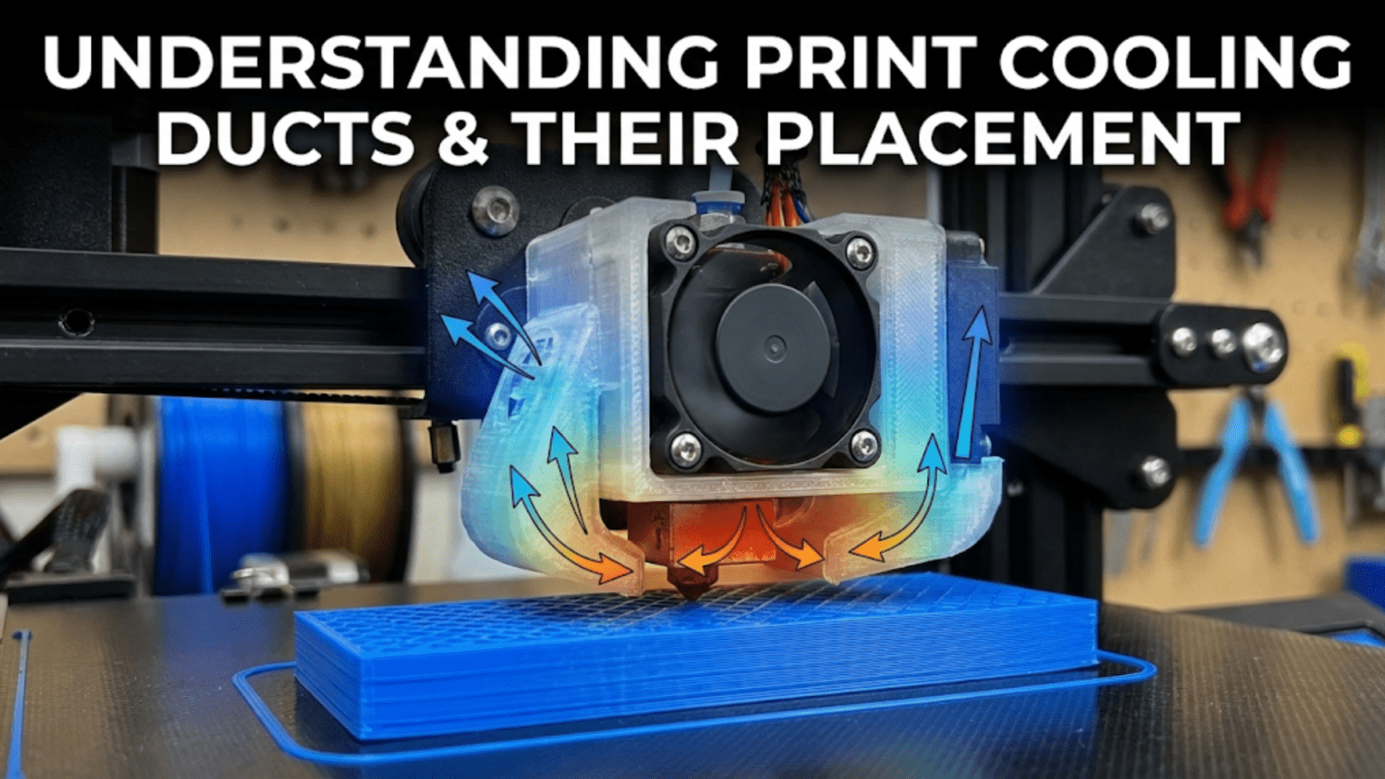
Print cooling ducts channel airflow from the part cooling fan directly onto the freshly extruded plastic at the nozzle tip, enabling rapid solidification that improves overhangs, bridges, and fine details by preventing sagging before the plastic hardens. Effective duct design features directional focusing (concentrating diffuse fan output into a targeted stream), multi-directional coverage (ideally 360° around the nozzle), close proximity to the extrusion point without obstructing the print, and heater block shielding (preventing air from cooling the hotend block and destabilizing temperature control), with proper placement critical for maximizing cooling effectiveness while minimizing interference.
Introduction
The difference between a perfect overhang and a drooping mess often comes down to one factor: part cooling. Freshly extruded plastic exits the nozzle molten and pliable. Without rapid cooling, gravity pulls unsupported plastic downward before it solidifies, creating sagging overhangs, drooping bridges, and blurred fine details. Adequate cooling transforms this molten plastic into solid material quickly enough that it maintains its intended shape.
Yet the cooling fan alone isn’t enough. A fan blowing air in all directions wastes most of its output, with only a small fraction reaching the critical area around the nozzle. The solution is a duct—a carefully designed airflow channel that captures the fan’s diffuse output and focuses it precisely where needed: at the freshly extruded plastic emerging from the nozzle.
Duct design significantly affects cooling effectiveness. Poor designs waste airflow, provide uneven cooling from only one direction, or blast air onto the heater block (destabilizing temperature control). Good designs focus airflow efficiently, provide even coverage from multiple directions, position the outlet close to the nozzle, and shield the heater block from unwanted cooling. Understanding these design principles helps you evaluate your printer’s duct, recognize upgrade opportunities, and optimize cooling for better print quality.
In this comprehensive guide, we’ll explore what makes cooling ducts effective, examine different design approaches, understand placement considerations, and learn to evaluate and improve your printer’s part cooling system.
Why Cooling Ducts Matter
Understanding the problems good ducts solve:
Focusing Diffuse Airflow
The Fan Output Problem:
- Axial fans blow air in expanding cone
- Air disperses as it travels from fan
- Only small fraction reaches nozzle area without duct
- Most airflow wasted cooling unintended areas
Duct Function:
- Captures fan output in defined area
- Channels air through constrained path
- Focuses flow into smaller, directed stream
- Delivers concentrated airflow to target
Effectiveness Multiplier:
- Good duct can increase effective cooling 3-5×
- Same fan, dramatically better results
- Enables lower fan speeds for equal cooling
- Or better cooling at same fan speed
Directional Control
Targeting the Extrusion Point:
- Cooling most effective immediately after extrusion
- Plastic still pliable, heat removal fastest
- Specific targeting maximizes effectiveness
- Prevents cooling areas that don’t need it
Multiple Direction Coverage:
- Single-side duct creates asymmetric cooling
- Print orientation affects overhang quality
- Multi-directional ducts provide even cooling
- Best designs approach 360° coverage
Minimizing Heater Block Cooling
Temperature Stability Problem:
- Cooling fan air can blow on heater block
- Removes heat needed for melting plastic
- PID control struggles to compensate
- Temperature fluctuations affect quality
Shielding Approach:
- Good ducts direct air around heater block
- Shield or deflect airflow away from block
- Maintain stable hotend temperature
- Allow PID to work effectively
Cooling Duct Design Principles
What separates effective from ineffective designs:
Airflow Path Efficiency
Internal Geometry:
- Smooth transitions reduce turbulence
- Gradual curves maintain flow velocity
- Avoid sharp turns (create resistance)
- Minimize internal restrictions
Cross-Sectional Area:
- Should match or gradually reduce from fan
- Too small creates excessive back-pressure
- Too large allows flow to slow/separate
- Optimum maintains velocity while controlling direction
Length Considerations:
- Shorter paths more efficient (less friction)
- Longer necessary for directional control
- Balance efficiency with placement needs
- Excessive length wastes pressure
Outlet Design
Nozzle Proximity:
- Closer outlets more effective
- Typical distance: 5-15mm from nozzle tip
- Too close risks collision with print
- Too far reduces cooling effectiveness
Outlet Size and Shape:
- Smaller outlets increase air velocity
- Multiple small outlets vs. single large
- Slot vs. circular openings
- Tradeoffs between focus and coverage
Angle of Attack:
- Directed at extrusion point
- Angled to cool freshly deposited plastic
- Avoid blowing directly upward (wastes energy)
- Consider print direction and part geometry
Multi-Directional Coverage
Single-Side Limitations:
- Cooling only from one direction
- Overhang quality varies by orientation
- Uneven part cooling
- Print direction matters significantly
Dual-Side Improvement:
- Two outlets opposite sides
- Better coverage, less orientation-dependent
- Still has cooling bias
- Significant improvement over single
Ring Ducts (360°):
- Air surrounds nozzle completely
- Orientation-independent cooling
- Most consistent results
- More complex design and installation
Heater Block Shielding
Isolation Approaches:
- Physical barriers between airflow and block
- Deflectors directing air around block
- Careful outlet positioning avoiding block
- Minimizing upward airflow near block
Temperature Impact:
- Poor shielding: 5-15°C temperature drop during cooling
- Good shielding: <5°C temperature change
- PID can’t compensate for major fluctuations
- Affects print quality and reliability
Common Duct Designs
Different approaches with varying effectiveness:
Stock/OEM Ducts
Typical Characteristics:
- Simple, low-cost designs
- Often single-side cooling
- Adequate but not optimal
- Room for improvement in most cases
Compromises:
- Balance cost with effectiveness
- Work with standard fan sizes
- Accommodate other toolhead components
- Meet minimum requirements
Limitations:
- Limited multi-directional coverage
- May not shield heater block well
- Outlet positioning often suboptimal
- Material quality variable
Single-Side Aftermarket
Improved Designs:
- Better airflow focusing than stock
- Optimized outlet placement
- Closer to nozzle
- Better shielding
Still Directional:
- Cooling from one side only
- Print orientation affects results
- Adequate for many applications
- Significant upgrade from poor stock
Examples:
- Fang duct designs
- Petsfang variants
- Simple focused ducts
Dual-Side Ducts
Two-Outlet Approach:
- Outlets on opposite sides
- Much better coverage than single
- Less orientation-dependent
- Good compromise design
Implementation:
- Two separate ducts from one fan
- OR dual fans with individual ducts
- Symmetrical cooling pattern
- Popular upgrade path
Effectiveness:
- Major improvement over single-side
- Not quite 360° but close for practical purposes
- Works well for most geometries
Ring Ducts (360°)
Complete Coverage:
- Air flows around entire nozzle
- Truly orientation-independent
- Best theoretical performance
- Most complex implementation
Design Challenges:
- Requires careful engineering
- Must not obstruct toolhead movement
- Difficult to get close to nozzle
- More material, weight
Performance:
- Excellent overhangs all directions
- Consistent cooling regardless of print geometry
- Best bridging performance
- Worth complexity for quality-focused users
Radial Blower Ducts
High-Pressure Approach:
- Radial (centrifugal) fans generate higher pressure
- Better for restrictive ducts
- Focused, powerful airflow
- Different duct geometry required
Advantages:
- More effective airflow delivery
- Can use longer, more complex ducts
- Compact fan size for given airflow
- Excellent for ring duct designs
Considerations:
- Louder than axial fans typically
- Different mounting requirements
- Duct design must match blower output
- Higher cost than simple axial fans
Duct Material and Manufacturing
How ducts are made affects performance:
3D Printed Ducts
Most Common Approach:
- Print custom designs in PLA or PETG
- Huge variety available online
- Easy to iterate and modify
- Community-driven improvements
Material Considerations:
- PLA: Easy to print, adequate for most
- PETG: Better heat resistance near hotend
- ABS/ASA: Good heat resistance, warping challenges
- Avoid materials that soften <80°C for near-hotend use
Print Quality Impact:
- Layer lines create internal roughness
- Affects airflow efficiency slightly
- Smooth prints better than rough
- Orient for optimal surface finish
Injection Molded
Commercial Ducts:
- Smooth internal surfaces
- Consistent manufacturing
- Better airflow efficiency than 3D printed
- Found on OEM printers or premium aftermarket
Cost:
- Tooling makes small runs expensive
- Only economical for large quantities
- Less variety than 3D printed options
Sheet Metal
Custom Fabrication:
- Bent/formed metal sheets
- Very smooth internal surfaces
- Excellent heat resistance
- Professional appearance
Complexity:
- Requires metalworking skills/equipment
- Harder to produce complex geometries
- Less common in consumer space
- Used in some high-end/industrial printers
Duct Placement Considerations
Where and how ducts mount affects effectiveness:
Clearance Requirements
Avoiding Collisions:
- Duct must not interfere with printed parts
- Consider maximum build height
- Account for steep overhangs
- Test clearance across full movement range
Toolhead Integration:
- Must fit among other components (hotend, probe, wiring)
- Limited space on compact toolheads
- May require compromise between ideal and practical
- Design must accommodate specific printer geometry
Symmetry vs. Asymmetry
Symmetric Mounting:
- Balanced left/right or front/back
- Easier to achieve even cooling
- Better for multi-directional ducts
- Preferred when space allows
Asymmetric Compromises:
- Sometimes necessary due to toolhead design
- Can still work well with proper design
- May affect print orientation sensitivity
- Account for in duct airflow design
Proximity to Nozzle
Closer is Better (to a point):
- 5-10mm from nozzle tip ideal
- Maximum cooling effectiveness
- Minimal air dispersion
- Risk of collision increases
Practical Limits:
- Clearance for part geometry
- Steep overhangs can reach outlet
- Compromises needed for safety
- 10-15mm more practical often
Fan Positioning
Direct vs. Remote Mounting:
- Direct: Fan mounted to duct directly, compact
- Remote: Fan mounted elsewhere, connected via tube/duct, flexible placement
Toolhead Weight:
- Direct mounting adds weight
- Affects acceleration limits
- Remote mounting reduces moving mass
- Balance weight vs. efficiency
Duct Comparison Table
| Duct Type | Coverage | Complexity | Effectiveness | Material | Best For |
|---|---|---|---|---|---|
| Stock Single-Side | Single direction | Simple | Basic | Varies | Stock printers, minimal cooling needs |
| Aftermarket Single | Single direction | Simple-Moderate | Good | 3D printed | Budget upgrade, PLA focus |
| Dual-Side | Two directions | Moderate | Very Good | 3D printed | General upgrade, balanced performance |
| Ring/360° | All directions | High | Excellent | 3D printed/injection | Maximum quality, all materials |
| Radial Blower | Focused | Moderate-High | Excellent | 3D printed | High performance, compact |
Evaluating Your Current Duct
Assessing existing cooling:
Performance Tests
Overhang Test:
- Print standard overhang test
- Angles from 30° to 80°
- Evaluate drooping/sagging
- Poor results indicate inadequate cooling
Bridge Test:
- Print bridges of various lengths
- 10mm, 20mm, 40mm, 60mm spans
- Measure sagging in middle
- Good cooling shows minimal sag
Fine Detail Test:
- Small features, thin walls
- Should remain crisp and defined
- Melted/blurred details indicate insufficient cooling
Directional Sensitivity:
- Rotate overhang test 90° and reprint
- Compare results from different orientations
- Single-side ducts show orientation dependence
Visual Inspection
Outlet Condition:
- Close to nozzle?
- Directed at extrusion point?
- Covering desired area?
- Any obvious design flaws?
Heater Block Exposure:
- Is block in airflow path?
- Temperature fluctuations during cooling fan changes?
- Shielding adequate?
Physical Condition:
- Damage or warping from heat?
- Mounting secure?
- Airflow path obstructed?
Upgrading Cooling Ducts
Improving performance:
Selection Criteria
Printer Compatibility:
- Matches toolhead design
- Fits available space
- Works with fan size/type
- Mounting points available
Performance Goals:
- Better overhangs: Multi-directional duct
- Maximum quality: Ring duct
- Simple upgrade: Improved single-side
- Specific material needs: Consider material requirements
Complexity Tolerance:
- Simple bolt-on replacement
- Moderate printing/assembly
- Complex multi-part design
- Custom fabrication
Popular Upgrade Ducts
Printer-Specific:
- Designed for common models
- Many options available
- Community testing and feedback
- Easy to find and implement
Universal Designs:
- Adaptable to various printers
- May require modification
- More flexible but less optimized
- DIY-friendly approach
Installation Tips
Test Fit First:
- Print in draft quality for testing
- Verify clearances before final print
- Check all movement ranges
- Make adjustments if needed
Print Quality:
- Use quality settings for final version
- Proper cooling for duct printing (ironic)
- Strong layer adhesion near hotend
- Consider print orientation for strength
Airflow Verification:
- Feel airflow at outlet
- Should be strong, focused stream
- Compare to stock if possible
- Adjust fan speed if needed
Troubleshooting Duct Problems
Common issues and solutions:
Insufficient Cooling:
- Check fan operation and speed
- Verify duct not obstructed
- Confirm outlet near nozzle
- May need better duct design
Temperature Instability:
- Duct cooling heater block
- Improve shielding
- Adjust duct position
- Consider different design
Collisions with Print:
- Duct too close or poorly positioned
- Reduce proximity
- Modify geometry
- Test clearance thoroughly
Uneven Cooling:
- Single-side duct limitation
- Upgrade to multi-directional
- Optimize print orientation
- Accept limitation or upgrade
Conclusion
Print cooling ducts transform diffuse fan output into focused airflow directed precisely where cooling matters most—at the freshly extruded plastic emerging from the nozzle. Good duct design dramatically improves overhang quality, bridge performance, and fine detail definition by ensuring rapid solidification before gravity deforms the still-molten plastic.
Understanding what makes ducts effective—efficient airflow paths, optimized outlet placement, multi-directional coverage, and heater block shielding—helps you evaluate your printer’s cooling system and recognize upgrade opportunities. The difference between a simple single-side duct and a well-designed ring duct can transform print quality, especially for challenging geometries with significant overhangs.
While stock ducts provide basic functionality, aftermarket designs often improve performance significantly. The variety of available designs—from simple single-side improvements through sophisticated 360° ring ducts—means solutions exist for every need and complexity tolerance. Even a modest duct upgrade can yield noticeable quality improvements for minimal cost and effort.
The next time you print an overhang that maintains its shape perfectly or a bridge that spans without sagging, appreciate the cooling duct making it possible. That carefully shaped plastic channel isn’t just directing air—it’s focusing your fan’s output into targeted cooling that solidifies plastic before gravity wins, enabling the complex geometries and fine details that make 3D printing so versatile.