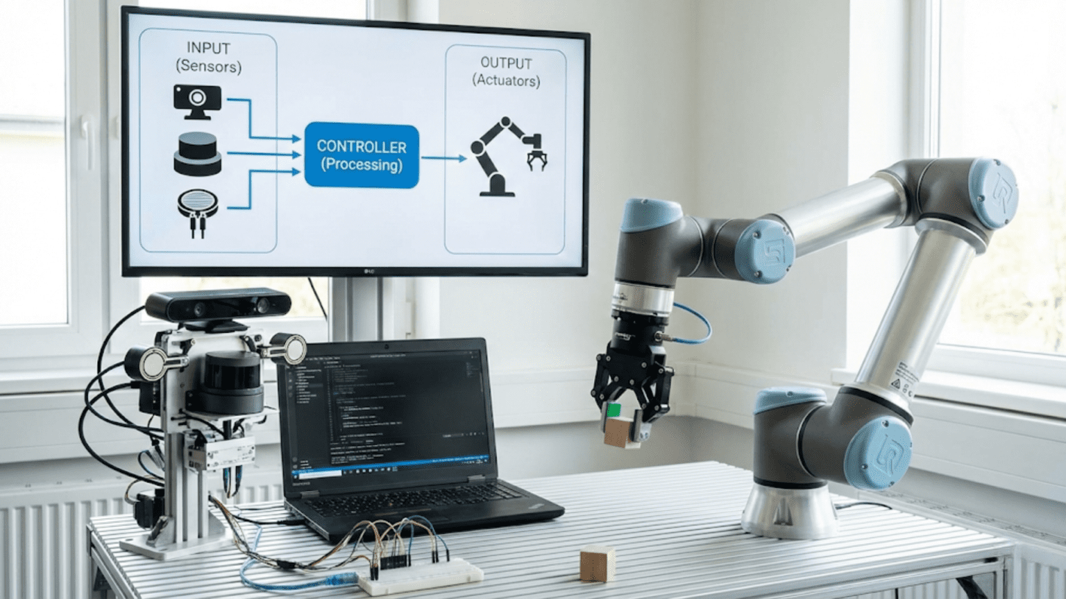
Input and output (I/O) in robotics programming refers to how your robot’s microcontroller communicates with the physical world—inputs receive information from sensors that detect environmental conditions like distance, light, or touch, while outputs send commands to actuators like motors, LEDs, and servos that create physical actions. Understanding I/O is fundamental to robotics because every sensor reading and every motor command flows through these digital and analog pathways that connect your code to hardware.
You write a program that should make your robot avoid obstacles, but it drives straight into walls as if blind. Or you command motors to spin, but nothing happens. Perhaps sensors are connected, but your code reads random nonsense instead of meaningful data. These frustrating scenarios stem from a fundamental misunderstanding: how your code actually communicates with physical hardware. Your program doesn’t directly “see” sensors or “control” motors—instead, it reads electrical signals from input pins and writes electrical signals to output pins. Understanding this input/output (I/O) layer transforms mysterious hardware problems into solvable programming challenges.
Input and output represent the bridge between abstract code and physical reality. On one side, you have software—variables, functions, logic, and algorithms executing invisibly inside a microcontroller. On the other side, you have hardware—sensors detecting light, distance, and motion; motors spinning wheels; servos positioning arms; LEDs providing feedback. I/O pins are where these two worlds meet, where voltage levels encode information flowing from sensors into your program and from your program out to actuators.
Every robotics project involves extensive I/O: reading sensor values to understand the environment, processing that information in your code, and sending commands to actuators to interact with the world. Whether you’re building a simple line follower or a sophisticated autonomous platform, you’ll spend significant time configuring pins, reading inputs, writing outputs, and debugging I/O problems. This article provides the comprehensive understanding you need to confidently work with inputs and outputs, transforming your robot from a collection of disconnected components into an integrated system where sensors inform decisions and those decisions drive physical actions.
The Fundamentals: What Are Inputs and Outputs?
Before diving into technical details, understanding what I/O means conceptually helps you think correctly about how robots interact with their environment.
Inputs: How Robots Perceive
Inputs are pathways for information to flow FROM the physical world INTO your program. Sensors detect environmental conditions—distance to obstacles, ambient light level, line position, temperature, or countless other parameters—and convert these physical phenomena into electrical signals that your microcontroller can measure.
When you “read a sensor” in code, you’re actually measuring the voltage level on an input pin that the sensor controls. The sensor might output high voltage (typically 5V or 3.3V) when detecting something and low voltage (0V) when not, or it might output a voltage that varies continuously with the measured quantity. Your program reads this voltage and interprets it as meaningful data.
Example inputs include:
- Button presses (digital: pressed or not pressed)
- Distance sensors (analog: varying voltage represents distance)
- Line sensors (digital: on line or off line)
- Temperature sensors (analog: voltage proportional to temperature)
- Encoders (digital pulses counting motor rotations)
- IMU sensors (digital data via communication protocol)
Outputs: How Robots Act
Outputs are pathways for commands to flow FROM your program OUT to physical actuators. When your code decides a motor should spin or an LED should light, it sets voltage levels on output pins. These voltage changes trigger external hardware—motor drivers activate motors, LED circuits light up, servo motors move to positions, speakers produce sounds.
When you “control an actuator” in code, you’re setting the voltage level on an output pin. Setting the pin HIGH outputs maximum voltage (5V or 3.3V); setting it LOW outputs 0V. For analog-style control, pulse width modulation (PWM) rapidly toggles the pin between HIGH and LOW at varying duty cycles to simulate intermediate voltages.
Example outputs include:
- LED indicators (digital: on or off)
- Motor control (analog PWM: speed control)
- Servo positioning (PWM: position control)
- Buzzer sounds (digital or PWM: on/off or frequency control)
- Relay switches (digital: circuit closed or open)
- Display modules (digital data via communication protocol)
The I/O Loop: Continuous Sensing and Acting
Robots continuously execute an I/O loop:
- Read inputs (sense environment)
- Process information (make decisions)
- Write outputs (take actions)
- Repeat
This endless cycle—sense, think, act, sense, think, act—is how robots operate autonomously. Your program orchestrates this loop, reading sensors many times per second, processing that data with control algorithms, and commanding actuators based on decisions.
Digital I/O: Binary States and Discrete Signals
Digital I/O deals with binary states—on or off, high or low, 1 or 0. While seemingly simple, digital I/O forms the foundation of robot control and enables many essential functions.
Digital Inputs: Reading Binary States
Digital inputs report one of two states: HIGH (voltage present, typically 5V or 3.3V) or LOW (no voltage, 0V). Your code reads this binary state and interprets its meaning.
Common digital input devices:
- Buttons/switches: HIGH when pressed, LOW when released (or vice versa with pullup resistors)
- Limit switches: Detect physical contact or position limits
- Binary proximity sensors: Detect presence/absence of objects
- Encoders: Provide digital pulses for position/speed measurement
- Digital line sensors: Report black or white under sensor
Configuring Digital Input Pins
Before reading a pin, configure it as an input using pinMode():
const int buttonPin = 2;

void setup() {
  pinMode(buttonPin, INPUT);  // Configure pin 2 as input
  Serial.begin(9600);
}

void loop() {
  int buttonState = digitalRead(buttonPin);  // Read current state

  if (buttonState == HIGH) {
    Serial.println("Button pressed!");
  } else {
    Serial.println("Button not pressed");
  }

  delay(100);
}Pull-up and Pull-down Resistors
Floating inputs (not connected to anything) read random values due to electrical noise. Pull-up or pull-down resistors prevent this by ensuring inputs have a defined state when not actively driven.
Pull-up resistor: Connects input to HIGH voltage through a resistor. Input reads HIGH by default; pressing a button that connects to ground makes it read LOW.
Pull-down resistor: Connects input to ground through a resistor. Input reads LOW by default; activating the input pulls it HIGH.
Arduino provides internal pull-up resistors you can activate:
pinMode(buttonPin, INPUT_PULLUP);  // Activate internal pull-up

// Now button reads HIGH when not pressed, LOW when pressed
if (digitalRead(buttonPin) == LOW) {
  Serial.println("Button pressed!");
}This is very convenient—no external resistors needed for simple buttons.
Digital Outputs: Controlling Binary Actuators
Digital outputs set pins to HIGH or LOW, controlling devices that need simple on/off states.
Common digital output devices:
- LEDs: On when HIGH, off when LOW
- Relays: Activated (circuit closed) when HIGH
- Digital motor drivers: Some accept HIGH/LOW for direction
- Buzzers: Sound when HIGH, silent when LOW
Configuring and Using Digital Outputs
Configure pins as outputs and control them with digitalWrite():
const int ledPin = 13;
const int motorPin = 9;

void setup() {
  pinMode(ledPin, OUTPUT);     // LED as output
  pinMode(motorPin, OUTPUT);   // Motor control as output
}

void loop() {
  digitalWrite(ledPin, HIGH);    // Turn LED on
  digitalWrite(motorPin, HIGH);  // Start motor
  delay(1000);

  digitalWrite(ledPin, LOW);     // Turn LED off
  digitalWrite(motorPin, LOW);   // Stop motor
  delay(1000);
}Debouncing Digital Inputs
Mechanical buttons don’t cleanly transition between states—they “bounce,” rapidly flickering between HIGH and LOW for several milliseconds when pressed or released. Reading during this bounce period gives false readings.
Software debouncing waits for the input to stabilize:
const int buttonPin = 2;
const int debounceDelay = 50;  // milliseconds

int lastButtonState = LOW;
int buttonState;
unsigned long lastDebounceTime = 0;

void loop() {
  int reading = digitalRead(buttonPin);

  // If state changed, reset debounce timer
  if (reading != lastButtonState) {
    lastDebounceTime = millis();
  }

  // If enough time passed since last change, accept new state
  if ((millis() - lastDebounceTime) > debounceDelay) {
    if (reading != buttonState) {
      buttonState = reading;

      // Only trigger action on button press (HIGH)
      if (buttonState == HIGH) {
        Serial.println("Button pressed (debounced)");
      }
    }
  }

  lastButtonState = reading;
}This ensures button presses are detected reliably without false triggers from bouncing.
Analog I/O: Continuous Values and Variable Signals
While digital I/O handles binary states, analog I/O deals with continuous ranges of values—essential for sensors measuring quantities like distance, temperature, or light intensity, and for smoothly controlling motor speeds.
Analog Inputs: Reading Variable Voltages
Analog inputs measure voltage levels and convert them to numerical values. Arduino’s analog-to-digital converter (ADC) reads voltages from 0V to the reference voltage (usually 5V or 3.3V) and converts them to numbers from 0 to 1023 (10-bit resolution).
Common analog input devices:
- Potentiometers: Variable resistors (user controls)
- Distance sensors: Output voltage proportional to distance
- Light sensors (photoresistors): Resistance varies with light
- Temperature sensors: Output voltage varies with temperature
- Pressure sensors: Voltage varies with applied pressure
- Joysticks: Two potentiometers for X/Y position
Reading Analog Inputs
Arduino Uno has six analog input pins (A0-A5). Read them with analogRead():
const int sensorPin = A0;

void setup() {
  Serial.begin(9600);
  // Note: Analog pins don't need pinMode() configuration
}

void loop() {
  int sensorValue = analogRead(sensorPin);  // Returns 0-1023

  // Convert to voltage (assuming 5V reference)
  float voltage = sensorValue * (5.0 / 1023.0);

  Serial.print("ADC Value: ");
  Serial.print(sensorValue);
  Serial.print(", Voltage: ");
  Serial.print(voltage);
  Serial.println("V");

  delay(100);
}Interpreting Analog Values
Raw ADC values (0-1023) often need conversion to meaningful units:
Distance sensor example: Many IR distance sensors output voltage inversely proportional to distance. The sensor datasheet provides a conversion formula or lookup table:
int rawValue = analogRead(distanceSensorPin);
float voltage = rawValue * (5.0 / 1023.0);

// Example conversion (specific to particular sensor model)
// Consult your sensor's datasheet for exact formula
float distance_cm = 27.86 * pow(voltage, -1.15);

Serial.print("Distance: ");
Serial.print(distance_cm);
Serial.println(" cm");Temperature sensor example: TMP36 outputs 10mV per degree Celsius, with 500mV at 0°C:
int rawValue = analogRead(tempSensorPin);
float voltage = rawValue * (5.0 / 1023.0);

// TMP36 conversion: (voltage - 0.5V) * 100 = temperature in °C
float temperature = (voltage - 0.5) * 100.0;

Serial.print("Temperature: ");
Serial.print(temperature);
Serial.println("°C");Analog Input Resolution and Noise
Arduino’s 10-bit ADC provides 1024 distinct levels across the voltage range. For a 5V reference, resolution is approximately 5V ÷ 1024 ≈ 4.9mV per step. This limits precision—you can’t detect voltage changes smaller than ~5mV.
Electrical noise causes readings to fluctuate even when the actual signal is stable. Mitigate noise with:
Averaging multiple readings:
const int numReadings = 10;
int total = 0;

for (int i = 0; i < numReadings; i++) {
  total += analogRead(sensorPin);
  delay(10);
}

int average = total / numReadings;Low-pass filtering:
// Simple exponential moving average
float smoothedValue = 0;
const float alpha = 0.1;  // Smoothing factor (0-1)

void loop() {
  int reading = analogRead(sensorPin);
  smoothedValue = (alpha * reading) + ((1 - alpha) * smoothedValue);

  Serial.println(smoothedValue);
  delay(10);
}Analog Outputs: PWM for Variable Control
Arduino doesn’t have true analog outputs (digital-to-analog converters), but pulse width modulation (PWM) simulates analog output by rapidly toggling digital pins between HIGH and LOW.
PWM varies the duty cycle—the percentage of time the pin is HIGH versus LOW. A 50% duty cycle means the pin is HIGH half the time and LOW half the time, averaging to half the maximum voltage. A 25% duty cycle averages to one-quarter voltage; 75% averages to three-quarters voltage.
Arduino Uno has six PWM-capable pins (3, 5, 6, 9, 10, 11), marked with ~ symbol.
Using PWM for Motor Speed Control
Control motor speed by varying PWM duty cycle—higher duty cycle means faster speed:
const int motorPin = 9;  // Must be PWM-capable pin

void setup() {
  pinMode(motorPin, OUTPUT);
}

void loop() {
  // Accelerate from stop to full speed
  for (int speed = 0; speed <= 255; speed++) {
    analogWrite(motorPin, speed);  // 0 = 0% duty cycle, 255 = 100%
    delay(20);
  }

  // Decelerate back to stop
  for (int speed = 255; speed >= 0; speed--) {
    analogWrite(motorPin, speed);
    delay(20);
  }
}Note: analogWrite() accepts values 0-255, not 0-1023 like analogRead() returns. This 8-bit resolution provides 256 speed levels.
Using PWM for LED Brightness
Create smooth fading effects by varying LED brightness:
const int ledPin = 6;  // PWM-capable pin

void setup() {
  pinMode(ledPin, OUTPUT);
}

void loop() {
  // Fade in
  for (int brightness = 0; brightness <= 255; brightness++) {
    analogWrite(ledPin, brightness);
    delay(5);
  }

  // Fade out
  for (int brightness = 255; brightness >= 0; brightness--) {
    analogWrite(ledPin, brightness);
    delay(5);
  }
}PWM Limitations
PWM simulates analog output but isn’t truly analog:
- Frequency limitations: PWM frequency on Arduino is ~490 Hz or ~980 Hz depending on pin. Some applications need different frequencies.
- Filtering required: Some devices need smoothing capacitors to convert PWM to steady voltage
- Not suitable for all applications: Audio, precision analog signals, or devices expecting true DC voltage may not work well with PWM
Practical I/O Examples: Common Robotics Scenarios
Let’s explore complete, practical examples demonstrating I/O concepts in real robotics applications.
Example 1: Obstacle Detection and Response
Read a digital proximity sensor and control motors based on detection:
// Pins
const int proximityPin = 2;     // Digital proximity sensor
const int motorLeftPin = 9;     // Left motor (PWM)
const int motorRightPin = 10;   // Right motor (PWM)

// Speed settings
const int forwardSpeed = 180;
const int turnSpeed = 150;

void setup() {
  pinMode(proximityPin, INPUT);
  pinMode(motorLeftPin, OUTPUT);
  pinMode(motorRightPin, OUTPUT);
  Serial.begin(9600);
}

void loop() {
  // INPUT: Read proximity sensor
  int obstacleDetected = digitalRead(proximityPin);

  // DECISION: Determine action based on input
  if (obstacleDetected == HIGH) {
    // Obstacle ahead - turn right
    Serial.println("Obstacle detected! Turning...");

    // OUTPUT: Control motors to turn
    analogWrite(motorLeftPin, turnSpeed);   // Left forward
    analogWrite(motorRightPin, 0);          // Right stopped
    delay(500);  // Turn for 500ms
  } else {
    // No obstacle - drive forward
    Serial.println("Path clear. Moving forward.");

    // OUTPUT: Control motors to move forward
    analogWrite(motorLeftPin, forwardSpeed);
    analogWrite(motorRightPin, forwardSpeed);
  }

  delay(50);  // Small delay for stability
}This example demonstrates the complete I/O cycle: read sensor input, process information, write motor outputs, repeat continuously.
Example 2: Light-Following Robot
Use analog light sensors to follow a light source:
// Pins
const int leftLightSensor = A0;   // Analog light sensor (left)
const int rightLightSensor = A1;  // Analog light sensor (right)
const int motorLeftPin = 9;       // Left motor (PWM)
const int motorRightPin = 10;     // Right motor (PWM)

// Parameters
const int baseSpeed = 150;
const float turnFactor = 0.5;  // How aggressively to steer

void setup() {
  pinMode(motorLeftPin, OUTPUT);
  pinMode(motorRightPin, OUTPUT);
  Serial.begin(9600);
}

void loop() {
  // INPUT: Read both light sensors
  int leftLight = analogRead(leftLightSensor);
  int rightLight = analogRead(rightLightSensor);

  // PROCESS: Calculate difference (which side sees more light?)
  int lightDifference = leftLight - rightLight;

  // Calculate steering adjustment based on difference
  int steeringAdjustment = lightDifference * turnFactor;

  // Calculate motor speeds
  int leftSpeed = baseSpeed + steeringAdjustment;
  int rightSpeed = baseSpeed - steeringAdjustment;

  // Constrain to valid PWM range
  leftSpeed = constrain(leftSpeed, 0, 255);
  rightSpeed = constrain(rightSpeed, 0, 255);

  // OUTPUT: Apply motor speeds
  analogWrite(motorLeftPin, leftSpeed);
  analogWrite(motorRightPin, rightSpeed);

  // Debug output
  Serial.print("Left: ");
  Serial.print(leftLight);
  Serial.print(", Right: ");
  Serial.print(rightLight);
  Serial.print(", Diff: ");
  Serial.print(lightDifference);
  Serial.print(", Speeds: ");
  Serial.print(leftSpeed);
  Serial.print("/");
  Serial.println(rightSpeed);

  delay(50);
}This demonstrates analog input processing—reading variable sensor values and using them to continuously adjust output levels for smooth, proportional control.
Example 3: User-Controlled Speed with Potentiometer
Allow user to adjust robot speed via potentiometer:
// Pins
const int speedPotPin = A0;      // Potentiometer for speed control
const int buttonPin = 2;          // Button to start/stop
const int motorPin = 9;           // Motor (PWM)

// Variables
bool motorRunning = false;
int lastButtonState = LOW;

void setup() {
  pinMode(buttonPin, INPUT_PULLUP);
  pinMode(motorPin, OUTPUT);
  Serial.begin(9600);
}

void loop() {
  // INPUT: Read button (with simple debouncing)
  int buttonState = digitalRead(buttonPin);

  if (buttonState == LOW && lastButtonState == HIGH) {
    // Button just pressed - toggle motor state
    motorRunning = !motorRunning;
    Serial.print("Motor ");
    Serial.println(motorRunning ? "STARTED" : "STOPPED");
    delay(50);  // Simple debounce
  }

  lastButtonState = buttonState;

  // INPUT: Read potentiometer
  int potValue = analogRead(speedPotPin);  // 0-1023

  // PROCESS: Convert pot value to motor speed
  int motorSpeed = map(potValue, 0, 1023, 0, 255);  // Map to PWM range

  // OUTPUT: Apply speed if motor is running
  if (motorRunning) {
    analogWrite(motorPin, motorSpeed);

    Serial.print("Speed: ");
    Serial.print(motorSpeed);
    Serial.print(" (");
    Serial.print((motorSpeed * 100) / 255);
    Serial.println("%)");
  } else {
    analogWrite(motorPin, 0);  // Motor off
  }

  delay(100);
}This shows combining digital input (button) and analog input (potentiometer) to create interactive control with user feedback.
Example 4: Multi-Sensor Decision Making
Use multiple inputs to make complex decisions:
// Pins
const int frontSensor = A0;      // Front distance sensor
const int leftSensor = A1;       // Left distance sensor
const int rightSensor = A2;      // Right distance sensor
const int motorLeftPin = 9;
const int motorRightPin = 10;
const int statusLED = 13;

// Thresholds
const int obstacleThreshold = 300;  // ADC value indicating obstacle
const int speed = 180;

void setup() {
  pinMode(motorLeftPin, OUTPUT);
  pinMode(motorRightPin, OUTPUT);
  pinMode(statusLED, OUTPUT);
  Serial.begin(9600);
}

void loop() {
  // INPUT: Read all sensors
  int frontDist = analogRead(frontSensor);
  int leftDist = analogRead(leftSensor);
  int rightDist = analogRead(rightSensor);

  // PROCESS: Evaluate conditions and decide action
  bool frontClear = (frontDist < obstacleThreshold);
  bool leftClear = (leftDist < obstacleThreshold);
  bool rightClear = (rightDist < obstacleThreshold);

  // Decision logic with priority
  if (frontClear) {
    // Path ahead clear - drive forward
    Serial.println("Forward");
    analogWrite(motorLeftPin, speed);
    analogWrite(motorRightPin, speed);
    digitalWrite(statusLED, LOW);  // Status: OK

  } else if (rightClear) {
    // Front blocked, right clear - turn right
    Serial.println("Turn Right");
    analogWrite(motorLeftPin, speed);
    analogWrite(motorRightPin, 0);
    digitalWrite(statusLED, HIGH);  // Status: Avoiding

  } else if (leftClear) {
    // Front blocked, left clear - turn left
    Serial.println("Turn Left");
    analogWrite(motorLeftPin, 0);
    analogWrite(motorRightPin, speed);
    digitalWrite(statusLED, HIGH);  // Status: Avoiding

  } else {
    // All paths blocked - back up
    Serial.println("Backup!");
    analogWrite(motorLeftPin, speed);
    analogWrite(motorRightPin, speed);
    // Note: This would require direction control pins in real implementation
    digitalWrite(statusLED, HIGH);  // Status: Trouble
  }

  // Debug output
  Serial.print("Sensors - Front: ");
  Serial.print(frontDist);
  Serial.print(", Left: ");
  Serial.print(leftDist);
  Serial.print(", Right: ");
  Serial.println(rightDist);

  delay(100);
}This demonstrates how multiple inputs inform complex decision-making with prioritized logic, producing coordinated output actions.
Pin Configuration Best Practices
Proper pin configuration prevents problems and ensures reliable robot operation.
Plan Your Pin Usage
Before connecting hardware, plan which pins serve which purposes:
Document your pin assignments:
// Pin Configuration
// Digital I/O:
const int buttonPin = 2;         // Input - Start button
const int proximitySensor = 3;   // Input - Obstacle detection
const int statusLED = 13;        // Output - Status indicator

// Analog Inputs:
const int distanceSensor = A0;   // Distance to wall
const int lightSensor = A1;      // Ambient light level

// PWM Outputs:
const int motorLeft = 9;         // Left motor speed
const int motorRight = 10;       // Right motor speed
const int servoPin = 11; // Gripper servoClear documentation prevents confusion and makes debugging easier.
Pin Capability Constraints
Not all pins are interchangeable—understand limitations:
Digital pins (0-13 on Uno):
- Can all be used for digital I/O
- Pins 0-1 also used for serial communication (avoid if using Serial)
- Pin 13 has built-in LED (convenient for testing)
Analog input pins (A0-A5 on Uno):
- Dedicated analog inputs
- Can also be used as digital I/O (reference as 14-19 or A0-A5)
PWM pins (3, 5, 6, 9, 10, 11 on Uno):
- Only these support analogWrite()
- Required for motor speed control, LED dimming, servo control
Special function pins:
- Pins 2 and 3: Support interrupts (advanced feature)
- Pins 10-13: SPI communication (if using SPI devices)
- Pins A4-A5: I2C communication (if using I2C devices)
Current Limitations
Arduino pins have current limits—violating them damages the microcontroller:
Per-pin limits:
- Maximum source current (output HIGH): ~40mA
- Maximum sink current (output LOW): ~40mA
- Recommended continuous current: 20mA or less
Total limits:
- Total current all pins: 200mA maximum
Implications:
- LEDs need current-limiting resistors (typically 220-330Ω)
- Motors, servos, and high-current devices need external drivers
- Never connect motors directly to Arduino pins
- Relays need transistor drivers
Voltage Levels
Ensure voltage compatibility between Arduino and connected devices:
5V Arduino (Uno, Mega):
- Logic HIGH: 5V
- Logic LOW: 0V
- Inputs tolerate 0-5V
- Outputs provide 0V or 5V
3.3V Arduino (Due, Zero, some others):
- Logic HIGH: 3.3V
- Logic LOW: 0V
- Inputs tolerate 0-3.3V (NOT 5V-safe!)
- Outputs provide 0V or 3.3V
Mixing voltages requires level shifters to prevent damage.
Common I/O Problems and Solutions
Even experienced roboticists encounter I/O issues. Recognizing common problems and their solutions saves debugging time.
Problem: Inputs Reading Random or Unstable Values
Symptoms: Digital inputs fluctuate randomly; analog inputs show constant noise; sensors give inconsistent readings.
Causes:
- Floating input (no pull-up/pull-down resistor)
- Loose or poor connections
- Electrical noise from motors or other sources
- Long wires acting as antennas
Solutions:
- Enable internal pull-ups: Use
INPUT_PULLUPfor digital inputs - Add external pull-down resistors: If pull-up isn’t appropriate (typically 10kΩ)
- Check connections: Verify all wires are secure
- Add filtering: Capacitors near sensors reduce noise
- Separate power: Use separate power supplies for motors and logic
- Shorten wires: Keep sensor wires as short as practical
- Average readings: Software averaging smooths noisy analog inputs
Problem: Outputs Not Working
Symptoms: LED doesn’t light; motor doesn’t spin; nothing happens when code runs.
Causes:
- Pin not configured as OUTPUT
- Wrong pin number in code
- Insufficient current (device draws more than pin provides)
- Wiring error (loose connection, wrong polarity)
- Device damaged or defective
Solutions:
- Verify pinMode: Ensure
pinMode(pin, OUTPUT)in setup - Check pin numbers: Confirm code matches physical connections
- Test with LED: Replace suspect device with LED to verify pin works
- Use external driver: High-current devices need transistors, relays, or motor drivers
- Check wiring: Verify correct polarity and secure connections
- Measure voltage: Use multimeter to confirm pin outputs expected voltage
Problem: Analog Readings Always Return 0 or 1023
Symptoms: analogRead() returns only minimum or maximum values, no intermediate values.
Causes:
- Sensor not powered
- Sensor shorted to ground (always 0) or VCC (always 1023)
- Wrong pin (reading unconnected pin)
- Sensor damaged
Solutions:
- Check power: Verify sensor receives appropriate voltage
- Test with potentiometer: Replace sensor with known-good potentiometer
- Verify pin number: Confirm using correct analog pin (A0-A5)
- Inspect wiring: Look for short circuits or broken connections
- Test sensor: Use multimeter to measure sensor’s output voltage directly
Problem: PWM Not Producing Expected Results
Symptoms: analogWrite() doesn’t control speed or brightness; device is only fully on or fully off.
Causes:
- Using non-PWM pin
- Device doesn’t respond to PWM (needs steady DC voltage)
- PWM frequency incompatible with device
- Insufficient current capability
Solutions:
- Use PWM pin: Only pins 3, 5, 6, 9, 10, 11 support PWM on Uno
- Verify device compatibility: Some devices need steady voltage, not PWM
- Add filtering: RC filter converts PWM to steady voltage if needed
- Use external driver: Motor drivers, MOSFET circuits provide higher current
- Check duty cycle range: Ensure using 0-255 range, not 0-1023
Problem: Interference Between Inputs and Outputs
Symptoms: Reading inputs affects outputs; motors cause sensors to misread; erratic behavior under load.
Causes:
- Inadequate power supply (voltage drops under load)
- Ground loops or poor grounding
- Electrical noise from motors coupling into sensor circuits
Solutions:
- Separate power supplies: Use one supply for motors, another for logic
- Common ground: Ensure all power supplies share common ground
- Filter motor power: Add capacitors across motor terminals
- Physical separation: Keep motor wires away from sensor wires
- Shielded cables: Use shielded wire for sensitive sensors
Comparison Table: Input and Output Types
| I/O Type | Signal Range | Arduino Function | Resolution | Typical Uses | Pin Requirements |
|---|---|---|---|---|---|
| Digital Input | HIGH or LOW | digitalRead() | 1 bit (2 states) | Buttons, switches, binary sensors | Any digital pin |
| Digital Output | HIGH or LOW | digitalWrite() | 1 bit (2 states) | LEDs, relays, digital control | Any digital pin |
| Analog Input | 0-5V (or 0-3.3V) | analogRead() | 10 bit (1024 levels) | Distance, light, temperature sensors | A0-A5 (analog pins) |
| PWM Output | 0-100% duty cycle | analogWrite() | 8 bit (256 levels) | Motor speed, LED brightness, servo | Pins 3,5,6,9,10,11 |
| Serial Communication | Digital data stream | Serial.print() | Variable (bytes) | Debugging, displays, complex sensors | Pins 0,1 (or software) |
| I2C Communication | Digital data + clock | Wire library | Variable (bytes) | Multi-device communication | A4 (SDA), A5 (SCL) |
| SPI Communication | Digital data + clock | SPI library | Variable (bytes) | High-speed device communication | 10-13 (MISO,MOSI,SCK,SS) |
Advanced I/O Concepts
Beyond basic digital and analog I/O, several advanced concepts become relevant as your projects increase in complexity.
Interrupts: Responding to Events Immediately
Normal I/O requires continuously polling (checking) inputs in your loop. Interrupts allow hardware events to immediately trigger functions, regardless of what your code is doing.
Use interrupts for:
- Encoder counting (don’t miss pulses)
- Emergency stops (immediate response critical)
- Button presses requiring instant reaction
- Timing-critical sensor reading
Example: Interrupt-driven button:
const int buttonPin = 2;  // Only pins 2 and 3 support interrupts on Uno
volatile int buttonPresses = 0;

void setup() {
  pinMode(buttonPin, INPUT_PULLUP);
  attachInterrupt(digitalPinToInterrupt(buttonPin), buttonISR, FALLING);
  Serial.begin(9600);
}

void loop() {
  // Main code continues running
  // buttonPresses updates automatically when button pressed
  Serial.print("Button presses: ");
  Serial.println(buttonPresses);
  delay(1000);
}

// Interrupt Service Routine (ISR)
void buttonISR() {
  buttonPresses++;  // Increment counter
}The ISR executes immediately when the button is pressed, even if loop() is busy with other tasks.
Analog Reference Voltage
By default, analogRead() measures 0-5V (on 5V Arduinos) and maps it to 0-1023. You can change the reference voltage for better resolution:
void setup() {
  analogReference(INTERNAL);  // Use internal 1.1V reference
  // Now analogRead() measures 0-1.1V mapped to 0-1023
  // Better resolution for low-voltage signals
}Options:
DEFAULT: 5V (or 3.3V on 3.3V boards)INTERNAL: 1.1V internal reference (better resolution for small signals)EXTERNAL: Use voltage applied to AREF pin as reference
Warning: Don’t apply external voltage to AREF when using INTERNAL reference—can damage Arduino.
Direct Port Manipulation
For advanced users needing maximum speed, you can directly manipulate port registers instead of using digitalWrite(). This is much faster but less portable:
// Normal way (slow but clear)
digitalWrite(13, HIGH);

// Fast way (direct port manipulation)
PORTB |= (1 << PB5); // Set pin 13 HIGH (PB5 is port B, bit 5)This is rarely necessary for beginners but becomes relevant for time-critical applications like generating precise waveforms or bit-banging communication protocols.
Conclusion: I/O as the Robot’s Nervous System
Input and output pins form your robot’s nervous system—the pathways connecting its electronic brain to the physical world. Just as your nervous system carries sensory information to your brain and motor commands to your muscles, I/O pins carry sensor data to your microcontroller and control signals to your actuators. Understanding I/O deeply transforms you from someone who copies code examples hoping they work into someone who confidently connects sensors and actuators, knowing exactly how data flows from the physical world through your program and back out to create actions.
The concepts in this article—digital versus analog, input versus output, PWM, pin configuration, troubleshooting—apply universally across microcontroller platforms. Whether you use Arduino, Raspberry Pi, ESP32, or professional embedded systems, the fundamental principles remain constant. The specific function names might differ, the voltage levels might vary, but the underlying concepts of reading inputs and writing outputs persist unchanged.
Every robotics project you build will involve extensive I/O work. You’ll read sensors to understand the environment, process that information with algorithms, and command actuators based on your decisions. The more comfortable you become with I/O concepts, the faster you’ll implement new sensors, debug connection problems, and create responsive, reliable robots that effectively interact with their world.
Start simple—read a button, light an LED, read a potentiometer, control a motor. As these basics become natural, add complexity: multiple sensors informing combined decisions, proportional control based on analog inputs, coordinated multi-actuator actions. Each project builds understanding and confidence, transforming I/O from a mysterious technical detail into an intuitive tool you wield effectively.
Remember that I/O problems are among the most common issues beginners face, but they’re also among the easiest to solve once you understand the fundamentals. When sensors don’t work as expected or actuators refuse to respond, systematically check: Is the pin configured correctly? Are connections secure? Is the device compatible with the voltage levels? Does the code use the right pin numbers and functions? These methodical checks resolve the vast majority of I/O issues.
Most importantly, I/O connects your programming skills to physical reality. The code you write doesn’t just manipulate abstract data—it controls real motors, reads real sensors, and makes real robots accomplish real tasks in the real world. That transformation from abstract instructions to physical actions is what makes robotics so engaging and rewarding. Master I/O, and you master the essential skill that turns code into robotic capability.