Making an LED blink represents the foundational “Hello World” program in robotics, teaching essential concepts including microcontroller programming, digital output control, timing functions, and the upload-compile-test cycle. This simple program demonstrates how software instructions control physical hardware, establishing the fundamental skill set needed for all subsequent robot programming projects.
Every robotics journey begins with a single blinking light. Before your robot navigates mazes, avoids obstacles, or performs complex tasks, you need to master the fundamental skill of controlling hardware with code. Making an LED blink might seem trivial—just turning a light on and off repeatedly—but this simple program teaches you the essential workflow, concepts, and debugging skills that underpin all robot programming. It’s the robotics equivalent of a chef learning to properly hold a knife or a musician practicing scales: unglamorous but absolutely foundational.
When you successfully make an LED blink for the first time, you’re not just illuminating a tiny component—you’re proving that you can write code, upload it to a microcontroller, and make physical hardware respond to your commands. You’re establishing the development cycle you’ll use for every future project: write code, compile it, upload it, observe results, debug problems, and iterate until it works. You’re learning how to control time, manage outputs, structure programs, and think in the logic that robots understand.
This article guides you through creating your first robot program step by step, from understanding what happens when code runs on a microcontroller through writing, uploading, and modifying your blink program. You’ll learn not just what to type but why each line exists, what it does, and how changing it affects behavior. By the end, you’ll have both a working program and the foundational knowledge needed to tackle progressively more complex robotics challenges.
Understanding What Happens When You Program a Robot
Before diving into code, understanding the relationship between your computer, your code, and the microcontroller helps demystify the programming process and prevents frustration when things don’t work as expected.
The Hardware-Software Interface
Your robot’s brain—typically an Arduino, Raspberry Pi, or similar microcontroller board—is fundamentally a tiny computer that executes instructions. Unlike the computer you’re reading this on, which runs complex operating systems and millions of lines of code simultaneously, microcontrollers run simple programs in an endless loop, executing one instruction at a time at remarkable speed.
The microcontroller contains:
- Processor (CPU): Executes your program instructions
- Memory (Flash): Stores your program permanently (even when powered off)
- RAM: Holds temporary data while the program runs
- Input/Output pins: Connect to external hardware (LEDs, motors, sensors)
- Clock: Provides precise timing for all operations
When you write a program, you’re creating a set of instructions that tells this processor exactly what to do: “Set pin 13 to HIGH voltage. Wait one second. Set pin 13 to LOW voltage. Wait one second. Repeat forever.” The processor follows these instructions literally and precisely, thousands of times per second.
The Development Cycle
Programming robots follows a consistent cycle regardless of project complexity:
- Write code: Type instructions in a programming language (C/C++ for Arduino)
- Compile: Translate human-readable code into machine code the processor understands
- Upload: Transfer compiled code to microcontroller’s flash memory
- Execute: Microcontroller runs the program
- Observe: Watch the robot’s behavior
- Debug: Identify and fix problems
- Iterate: Repeat the cycle with improvements
This cycle takes seconds for a blink program but remains the same whether you’re blinking an LED or programming an autonomous vehicle. Mastering this workflow is as important as learning syntax.
Why LEDs Make Perfect First Outputs
LEDs (Light-Emitting Diodes) are ideal for first programs because:
- Immediate visual feedback: You instantly see whether your code works
- Simple connection: Usually just two wires (power and ground)
- Low power requirements: Won’t damage your board if connected incorrectly
- Digital output: On or off, no complex analog control needed
- Built-in on many boards: Arduino boards include an LED on pin 13 requiring no external components
Starting with LEDs establishes confidence before tackling more complex outputs like motors or servos that involve higher currents, more complex control, and greater potential for hardware damage if programmed incorrectly.
Setting Up Your Arduino Development Environment
Before writing code, you need the tools to write, compile, and upload programs to your Arduino board.
Required Hardware
For this tutorial, you need:
- Arduino board: Arduino Uno is recommended for beginners (Leonardo, Mega, or compatible clones also work)
- USB cable: Appropriate for your Arduino model (usually USB A to B for Uno)
- Computer: Windows, Mac, or Linux with internet connection
- LED (optional): If using external LED instead of built-in
The Arduino Uno includes a built-in LED connected to pin 13, so you can complete this entire tutorial without any additional components—just the board and USB cable.
Installing the Arduino IDE
The Arduino Integrated Development Environment (IDE) is free software that provides everything needed to program Arduino boards:
- Download: Visit arduino.cc/en/software and download the IDE for your operating system
- Install: Run the installer, accepting default settings
- Launch: Open the Arduino IDE application
The IDE interface includes:
- Code editor: Where you write your program
- Toolbar: Buttons for verify (compile), upload, and other functions
- Console: Displays compilation messages and errors
- Status bar: Shows board type and connection status
Connecting Your Arduino
- Plug in: Connect Arduino to your computer using the USB cable
- Wait for drivers: Your operating system should automatically install necessary drivers (may take 30-60 seconds)
- Select board: In Arduino IDE, go to Tools → Board → Arduino Uno (or your model)
- Select port: Go to Tools → Port and select the port showing your Arduino (usually something like “COM3” on Windows or “/dev/cu.usbmodem” on Mac)
If your board doesn’t appear, troubleshoot by:
- Trying a different USB cable (some cables are power-only without data lines)
- Trying a different USB port
- Checking Device Manager (Windows) or System Report (Mac) to verify the board is recognized
- Installing drivers manually if needed (usually only required for clone boards)
Verifying the Setup
Test your setup with the pre-installed example:
- Go to File → Examples → 01.Basics → Blink
- Click the Upload button (right arrow icon in toolbar)
- Watch for “Done uploading” message
- Observe the LED on pin 13 blinking
If the LED blinks, your setup is complete and working! If not, check connections and driver installation before proceeding.
Your First Blink Program: Code Walkthrough
Let’s examine the complete blink program, understanding what each line does and why it exists. Here’s the entire program:
// Blink Program - Your First Robot Code
void setup() {
pinMode(13, OUTPUT);
}
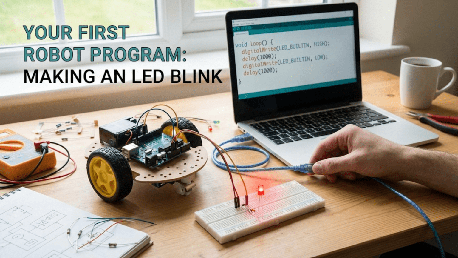
void loop() {
digitalWrite(13, HIGH);
delay(1000);
digitalWrite(13, LOW);
delay(1000);
}This short program contains everything needed to make an LED blink. Let’s analyze each component in detail.
Comments: Explaining Your Code
// Blink Program - Your First Robot CodeLines beginning with // are comments—notes for humans that the compiler completely ignores. Comments don’t affect program behavior but help you (and others) understand what the code does. Good commenting habits established now will save hours of confusion in complex future projects.
You can also create multi-line comments:
/*
   This is a multi-line comment.
   Everything between the opening and closing
   symbols is ignored by the compiler.
*/The setup() Function: Initialization
void setup() {
  pinMode(13, OUTPUT);
}Every Arduino program must include a setup() function. This function runs exactly once when the Arduino powers on or resets. You use setup() to configure pins, initialize sensors, set up communication, and perform other one-time preparations.
void: This keyword means the function doesn’t return any value. Don’t worry about this for now—just know that setup() always starts with void.
setup(): The function name. The parentheses () can contain parameters (inputs to the function), but setup() takes no parameters, so they’re empty.
Curly braces { }: Everything between the opening { and closing } is part of the setup function—these are the instructions that execute once at startup.
pinMode(13, OUTPUT): This is the actual instruction inside setup(). It configures pin 13 as an output pin.
pinModeis a function that configures how a pin behaves13is the pin number we’re configuringOUTPUTtells the Arduino we want to control this pin (send voltage out), not read from it
The semicolon ; at the end is crucial—it marks the end of an instruction, like a period ends a sentence. Forgetting semicolons causes compiler errors.
The loop() Function: Main Program
void loop() {
digitalWrite(13, HIGH);
delay(1000);
digitalWrite(13, LOW);
delay(1000);
}After setup() completes, the Arduino immediately begins executing loop() and then repeats it forever—thousands of times per second unless you explicitly tell it to wait. This endless repetition is how robots continuously monitor sensors and control outputs.
digitalWrite(13, HIGH): Turns the LED on.
digitalWriteis a function that sets a digital pin to either HIGH (5V on most Arduinos) or LOW (0V)13is the pin numberHIGHmeans set this pin to high voltage (5V), which lights the LED
delay(1000): Waits for 1000 milliseconds (1 second).
delayis a function that pauses program execution1000is the number of milliseconds to wait- 1000 milliseconds = 1 second
During this delay, the LED stays lit because the last instruction set it to HIGH.
digitalWrite(13, LOW): Turns the LED off.
- Same as before, but
LOWmeans set the pin to 0V - This turns off the LED
delay(1000): Waits another second.
- LED remains off during this delay
End of loop() and repeat: When the program reaches the closing }, it immediately jumps back to the beginning of loop() and executes all instructions again. This creates the blinking pattern: on for one second, off for one second, on for one second, and so on forever.
Writing and Uploading Your First Program
Now let’s write the blink program yourself rather than using the pre-loaded example. This hands-on experience teaches the development workflow.
Creating a New Sketch
- Open Arduino IDE
- Create new sketch: File → New (or close the example if one is open)
- Delete default code: The IDE provides a template with empty
setup()andloop()functions—delete everything
You now have a blank editor ready for your first program.
Typing the Program
Carefully type the complete blink program exactly as shown earlier. Pay attention to:
- Capitalization matters:
OUTPUTworks,outputdoesn’t - Spelling matters:
digitalWriteworks,digitalwritedoesn’t - Punctuation matters: Missing semicolons, parentheses, or braces cause errors
- Spacing doesn’t matter much: Extra spaces and blank lines are ignored, but consistent formatting improves readability
Common beginner mistakes to avoid:
- Forgetting semicolons at the end of instructions
- Mismatching curly braces (every
{needs a corresponding}) - Misspelling function names
- Using lowercase instead of uppercase for keywords like
HIGHandOUTPUT
Compiling Your Program
Before uploading, compile (verify) your code to catch errors:
- Click the Verify button (checkmark icon in toolbar)
- Watch the console: The IDE compiles your code and reports results
- Success: If you see “Done compiling” with no errors, you’re ready to upload
- Errors: If you see error messages, read them carefully—they usually indicate which line has problems
Error messages can seem cryptic, but they often provide hints:
'OUTPUT' was not declared in this scope→ You misspelled OUTPUT or forgot to capitalize itexpected ';' before...→ You forgot a semicolon on the previous line'digitalwrite' was not declared→ You misspelled digitalWrite
Fix any errors and verify again until compilation succeeds.
Uploading to Your Arduino
Once compilation succeeds:
- Verify Arduino is connected: Check that the correct board and port are selected in the Tools menu
- Click Upload button (right arrow icon)
- Watch for LED activity: The TX/RX LEDs on the Arduino should flash rapidly during upload
- Wait for completion: Console should show “Done uploading”
- Observe the result: Pin 13 LED should immediately start blinking—on for one second, off for one second
Success! You’ve written, compiled, and uploaded your first robot program. The LED blinking proves your code is running on the hardware.
Troubleshooting Upload Problems
If upload fails, check these common issues:
“Serial port not found” error:
- Verify Arduino is plugged in
- Check correct port is selected in Tools → Port
- Try different USB cable or port
- Install drivers if needed (for clone boards)
“Programmer is not responding” error:
- Select correct board type in Tools → Board
- Try pressing the reset button on Arduino just before uploading
- Check USB cable supports data (not power-only)
Upload appears successful but LED doesn’t blink:
- Verify you’re looking at the correct LED (labeled “L” or “13” near pin 13)
- Check if a different program might be loaded (try uploading again)
- Verify the LED isn’t damaged (rare on built-in LED)
Modifying the Program: Learning Through Experimentation
The best way to understand code is to modify it and observe how behavior changes. Let’s experiment with variations of the blink program.
Experiment 1: Changing Blink Speed
Modify the delay() values to change how fast the LED blinks:
void loop() {
digitalWrite(13, HIGH);
delay(100); // Changed from 1000 to 100
digitalWrite(13, LOW);
delay(100); // Changed from 1000 to 100
}Result: LED blinks much faster—on for 0.1 seconds, off for 0.1 seconds. The LED appears to flicker.
Try different values:
delay(2000): Slow blinking (2-second intervals)delay(500): Medium speed (half-second intervals)delay(50): Very fast (barely visible as separate blinks)delay(10): So fast it appears dimly lit rather than blinking
What you’re learning: The delay() parameter controls timing. Smaller numbers mean shorter delays and faster actions.
Experiment 2: Asymmetric Blinking
Make the on-time and off-time different:
void loop() {
digitalWrite(13, HIGH);
delay(200); // Short on-time
digitalWrite(13, LOW);
delay(1800); // Long off-time
}Result: Quick flash (0.2 seconds on) followed by long darkness (1.8 seconds off). Total cycle is 2 seconds but asymmetric.
Try variations:
- Long on, short off (visual “heartbeat”)
- Very short on, long off (brief flash like a lighthouse)
- Random-seeming patterns by varying both delays
What you’re learning: You can control on-time and off-time independently. Different delay values create different timing patterns.
Experiment 3: Multiple Blinks Per Cycle
Create a pattern with multiple blinks:
void loop() {
// First blink
digitalWrite(13, HIGH);
delay(200);
digitalWrite(13, LOW);
delay(200);
// Second blink
digitalWrite(13, HIGH);
delay(200);
digitalWrite(13, LOW);
delay(200);
// Long pause before repeating
delay(1000);
}Result: Two quick blinks followed by a pause, then the pattern repeats. This creates a distinct two-pulse pattern.
Try variations:
- Three blinks (add another on-off pair)
- Morse code SOS: three short, three long, three short
- Custom patterns matching your preferences
What you’re learning: Programs execute instructions sequentially from top to bottom. You can create complex patterns by arranging simple commands in specific orders.
Experiment 4: Using Variables
Instead of hard-coding delay values, use variables to make the program easier to modify:
int delayTime = 1000; // Variable holding delay value
void setup() {
  pinMode(13, OUTPUT);
}
void loop() {
digitalWrite(13, HIGH);
delay(delayTime); // Use variable instead of number
digitalWrite(13, LOW);
delay(delayTime); // Use variable instead of number
}Result: Identical behavior to original program, but now you can change the blink speed by modifying just one number (the variable) instead of changing it in multiple places.
Try modifying delayTime:
- Set it to 500 for faster blinking
- Set it to 2000 for slower blinking
What you’re learning: Variables store values you can use repeatedly. When you need to use the same number in multiple places, variables make your code easier to maintain and modify.
Experiment 5: Two Different Variables
Use separate variables for on-time and off-time:
int onTime = 200;
int offTime = 1800;

void setup() {
  pinMode(13, OUTPUT);
}

void loop() {
  digitalWrite(13, HIGH);
  delay(onTime);
  digitalWrite(13, LOW);
  delay(offTime);
}Result: LED flashes briefly (200ms) with long off periods (1800ms).
What you’re learning: You can use multiple variables to independently control different aspects of behavior. This flexibility becomes essential in complex programs.
Adding an External LED: Expanding Your Circuit
The built-in LED is convenient for learning, but robots need to control external components. Let’s connect an external LED to practice working with real hardware.
Required Components
- 1 × LED (any color)
- 1 × 220-330 Ω resistor
- 2 × jumper wires
- 1 × breadboard (recommended but not required)
Understanding LED Polarity
LEDs are polarized—they only work when connected in the correct direction:
- Anode (positive, longer leg): Connects to the Arduino pin
- Cathode (negative, shorter leg): Connects to ground
If the LED doesn’t light, try reversing it—you can’t damage the LED by connecting it backward, it simply won’t light.
Why Resistors Are Required
LEDs have very low resistance and will draw excessive current if connected directly to a power source, quickly burning out. The resistor limits current to a safe level. For Arduino’s 5V output with standard LEDs, 220-330 Ω resistors work well.
The exact value isn’t critical for learning purposes:
- Too small (under 100 Ω): LED might be damaged
- Too large (over 1000 Ω): LED will be dim
- 220-330 Ω: Bright LED, safe current
Connecting the Circuit
Option 1: Using a Breadboard
- Insert LED into breadboard (any two holes in different rows)
- Connect resistor from LED anode (longer leg) to another breadboard hole
- Connect wire from resistor to Arduino pin 13
- Connect wire from LED cathode (shorter leg) to Arduino GND pin
Option 2: Direct Connection
- Connect resistor to LED anode (longer leg)
- Connect wire from resistor to Arduino pin 13
- Connect wire from LED cathode to Arduino GND pin
- Ensure connections are secure (twist wires together if needed)
Testing the External LED
Upload the same blink program—no code changes needed! The external LED should blink along with the built-in LED since they’re both connected to pin 13.
If the external LED doesn’t light:
- Verify all connections are secure
- Try reversing the LED (swap anode and cathode)
- Check resistor is in the circuit
- Confirm pin 13 is specified in the code
- Test the LED with a battery to verify it works
Using Different Pins
To use a different pin (say, pin 7):
void setup() {
  pinMode(7, OUTPUT);    // Changed from 13 to 7
}

void loop() {
  digitalWrite(7, HIGH);  // Changed from 13 to 7
  delay(1000);
  digitalWrite(7, LOW);   // Changed from 13 to 7
  delay(1000);
}Move your external LED’s wire from pin 13 to pin 7. Upload the program and verify the external LED blinks while the built-in LED (still on pin 13) stays off.
What you’re learning: Arduino has multiple digital pins (pins 2-13 on Uno), and you can control any of them the same way. This scalability allows controlling many LEDs, motors, or other outputs simultaneously.
Controlling Multiple LEDs: Parallel Outputs
Real robots control multiple outputs simultaneously. Let’s expand to multiple LEDs to demonstrate this capability.
Circuit Setup
Build three LED circuits, each connected to different pins:
- LED 1: Connected to pin 8
- LED 2: Connected to pin 9
- LED 3: Connected to pin 10
Each LED needs its own resistor and connection to ground, but all can share the same ground connection.
Basic Multiple LED Program
void setup() {
  pinMode(8, OUTPUT);
  pinMode(9, OUTPUT);
  pinMode(10, OUTPUT);
}

void loop() {
  // Turn all LEDs on
  digitalWrite(8, HIGH);
  digitalWrite(9, HIGH);
  digitalWrite(10, HIGH);
  delay(1000);

  // Turn all LEDs off
  digitalWrite(8, LOW);
  digitalWrite(9, LOW);
  digitalWrite(10, LOW);
  delay(1000);
}Result: All three LEDs blink in unison—all on for one second, all off for one second.
Sequential LED Pattern
Create a chasing pattern where LEDs light one at a time:
void setup() {
  pinMode(8, OUTPUT);
  pinMode(9, OUTPUT);
  pinMode(10, OUTPUT);
}

void loop() {
  // LED 1 on, others off
  digitalWrite(8, HIGH);
  digitalWrite(9, LOW);
  digitalWrite(10, LOW);
  delay(300);

  // LED 2 on, others off
  digitalWrite(8, LOW);
  digitalWrite(9, HIGH);
  digitalWrite(10, LOW);
  delay(300);

  // LED 3 on, others off
  digitalWrite(8, LOW);
  digitalWrite(9, LOW);
  digitalWrite(10, HIGH);
  delay(300);
}Result: LEDs light sequentially—first LED 1, then LED 2, then LED 3, then the pattern repeats. This creates a “chasing” or “scanning” effect.
Complex Patterns
Create your own patterns by varying which LEDs are on or off at each step:
void loop() {
  // Pattern 1: Left to right
  digitalWrite(8, HIGH);
  delay(200);
  digitalWrite(9, HIGH);
  delay(200);
  digitalWrite(10, HIGH);
  delay(200);

  // Pattern 2: All off
  digitalWrite(8, LOW);
  digitalWrite(9, LOW);
  digitalWrite(10, LOW);
  delay(500);

  // Pattern 3: Alternating
  digitalWrite(8, HIGH);
  digitalWrite(10, HIGH);
  delay(300);
  digitalWrite(8, LOW);
  digitalWrite(10, LOW);
  digitalWrite(9, HIGH);
  delay(300);
  digitalWrite(9, LOW);
  delay(300);
}What you’re learning: You can control multiple outputs independently, creating complex coordinated patterns. This skill directly translates to controlling multiple motors, servos, or other robot actuators.
Understanding the Code Structure Better
Now that you’ve experimented with the blink program, let’s examine some deeper programming concepts that will become important as you progress.
Functions: Reusable Code Blocks
setup() and loop() are functions—named blocks of code that perform specific tasks. Arduino requires these two functions, but you can create your own custom functions too:
void blinkLED() {
  digitalWrite(13, HIGH);
  delay(500);
  digitalWrite(13, LOW);
  delay(500);
}

void setup() {
  pinMode(13, OUTPUT);
}

void loop() {
  blinkLED();  // Call our custom function
  blinkLED();  // Call it again
  delay(1000); // Pause between sets
}Result: LED blinks twice quickly, pauses, then repeats. The blinkLED() function encapsulates the on-off sequence, making it easy to reuse.
What you’re learning: Functions let you organize code into reusable pieces. Instead of repeating the same instructions, you define them once and call them whenever needed.
Data Types: Different Kinds of Values
You’ve seen int (integer) used for variables. Arduino supports several data types:
int wholeNumber = 100;           // Integer: -32768 to 32767
long bigNumber = 1000000;        // Larger integer
float decimalNumber = 3.14;      // Decimal number
byte smallNumber = 255;          // Small integer: 0 to 255
boolean isOn = true; // True or falseFor most timing and pin control, int works fine. You’ll use other types as programs become more complex.
Constants: Values That Don’t Change
For values that never change during program execution, use const:
const int ledPin = 13;
const int delayTime = 1000;

void setup() {
  pinMode(ledPin, OUTPUT);
}

void loop() {
  digitalWrite(ledPin, HIGH);
  delay(delayTime);
  digitalWrite(ledPin, LOW);
  delay(delayTime);
}Using constants makes code more readable (meaningful names instead of numbers) and prevents accidental modification.
Serial Monitor: Seeing What Your Program Thinks
The Serial Monitor lets your Arduino communicate with your computer, displaying messages that help you understand what’s happening:
void setup() {
  pinMode(13, OUTPUT);
  Serial.begin(9600);  // Initialize serial communication
  Serial.println("Blink program started!");
}

void loop() {
  Serial.println("LED turning ON");
  digitalWrite(13, HIGH);
  delay(1000);

  Serial.println("LED turning OFF");
  digitalWrite(13, LOW);
  delay(1000);
}After uploading, open the Serial Monitor (Tools → Serial Monitor or magnifying glass icon). You’ll see messages displaying each time the LED changes state.
What you’re learning: Serial communication lets you debug programs by seeing what’s happening internally. This becomes invaluable for complex robots where you can’t visually see sensor values or internal calculations.
Common Problems and Solutions
Even simple programs can encounter issues. Understanding common problems and their solutions builds troubleshooting skills.
Problem: LED Doesn’t Blink
Symptoms: Code uploads successfully but LED doesn’t light or blink.
Possible Causes and Solutions:
- Wrong pin number in code
- Check code specifies correct pin (13 for built-in LED)
- Verify external LED is connected to the pin specified in code
- LED connected backward (external LED only)
- Reverse the LED—swap anode and cathode connections
- Look for longer leg (anode) connecting to Arduino pin
- No resistor (external LED only)
- LED might be burned out from excessive current
- Add appropriate resistor (220-330 Ω)
- Loose connections (external LED only)
- Check all wires are firmly connected
- Verify breadboard connections are in correct holes
- Different program loaded
- Upload the blink program again
- Verify “Done uploading” message appears
Problem: Code Won’t Compile
Symptoms: Error messages appear when clicking Verify button.
Common Errors and Fixes:
“expected ‘;’ before ‘}'”
- You forgot a semicolon on a previous line
- Add
;at the end of the indicated line
“‘OUTPUT’ was not declared”
- Misspelled or incorrect capitalization
- Change to
OUTPUT(all capitals)
“‘digitalwrite’ was not declared”
- Incorrect function name capitalization
- Change to
digitalWrite(capital W)
“expected ‘}’ at end of input”
- Mismatched curly braces
- Count opening
{and closing}— they should match - Check each function has both opening and closing braces
Problem: Code Uploads But Doesn’t Start
Symptoms: Upload succeeds but LED doesn’t blink; no error messages.
Solutions:
- Press reset button on Arduino to restart the program
- Check power: Verify Arduino has power (power LED should be lit)
- Re-upload: Upload the program again
- Try different code: Upload the built-in Blink example to verify Arduino works
Problem: Erratic Behavior
Symptoms: LED blinks irregularly or behaves unpredictably.
Solutions:
- Check code carefully: Look for typos or missing instructions
- Verify delay values: Ensure delays are reasonable (not 0, not negative)
- Check power supply: Weak power can cause erratic behavior
- Verify connections: Loose wires can create intermittent contact
Expanding Your Skills: Next Steps
Once you’ve mastered the basic blink program, you’re ready to explore more advanced variations that build on these foundational skills.
Adding Button Control
Make the LED respond to button presses:
const int ledPin = 13;
const int buttonPin = 2;

void setup() {
  pinMode(ledPin, OUTPUT);
  pinMode(buttonPin, INPUT_PULLUP);
}

void loop() {
  int buttonState = digitalRead(buttonPin);

  if (buttonState == LOW) {  // Button pressed (pulled to ground)
    digitalWrite(ledPin, HIGH);
  } else {
    digitalWrite(ledPin, LOW);
  }
}This introduces reading digital inputs and conditional logic—essential skills for sensor-based robots.
PWM: Controlling LED Brightness
Instead of just on/off, use pulse width modulation (PWM) to control brightness:
const int ledPin = 9;  // Must use PWM-capable pin (3, 5, 6, 9, 10, 11 on Uno)

void setup() {
  pinMode(ledPin, OUTPUT);
}

void loop() {
  // Fade in
  for (int brightness = 0; brightness <= 255; brightness++) {
    analogWrite(ledPin, brightness);
    delay(10);
  }

  // Fade out
  for (int brightness = 255; brightness >= 0; brightness--) {
    analogWrite(ledPin, brightness);
    delay(10);
  }
}This creates a breathing effect and introduces analog output control—useful for motor speed control.
State Machines: Complex Behavior
Implement different LED patterns based on internal state:
const int ledPin = 13;
int state = 0;

void setup() {
  pinMode(ledPin, OUTPUT);
}

void loop() {
  if (state == 0) {
    // Fast blinking
    digitalWrite(ledPin, HIGH);
    delay(100);
    digitalWrite(ledPin, LOW);
    delay(100);
  }
  else if (state == 1) {
    // Slow blinking
    digitalWrite(ledPin, HIGH);
    delay(1000);
    digitalWrite(ledPin, LOW);
    delay(1000);
  }
  else if (state == 2) {
    // Always on
    digitalWrite(ledPin, HIGH);
  }

  // This simple version stays in state 0 forever
  // In a real robot, you'd change state based on sensors or time
}This introduces state-based programming—how robots switch between different behaviors.
Comparison Table: LED Control Methods
| Method | Complexity | Control Type | Brightness Levels | Best For | Limitations |
|---|---|---|---|---|---|
| digitalWrite (ON/OFF) | Very Simple | Digital | 2 (on/off) | Learning basics, status indicators | Only on or off, no brightness control |
| digitalWrite with delays | Simple | Digital | 2 (on/off) | Blinking patterns, timing practice | Blocks program execution during delays |
| analogWrite (PWM) | Moderate | Analog | 256 (0-255) | LED dimming, motor speed | Only certain pins support PWM |
| FastLED library | Advanced | Digital + analog | Millions (RGB) | Complex lighting effects, RGB LEDs | Requires external library, more complex code |
| Interrupt-based | Advanced | Digital | 2 (on/off) | Time-critical applications | Complex to understand for beginners |
Beyond the Blink: Applying These Skills to Robotics
The skills you’ve learned from making an LED blink directly translate to controlling robot hardware:
Motors Instead of LEDs
The same digitalWrite() commands that control LEDs can control motor drivers:
const int motorPin = 9;

void setup() {
  pinMode(motorPin, OUTPUT);
}

void loop() {
  digitalWrite(motorPin, HIGH);  // Motor forward
  delay(2000);
  digitalWrite(motorPin, LOW);   // Motor stop
  delay(1000);
}This basic on/off control starts motors. More sophisticated control uses PWM (analogWrite) for speed variation.
Servos for Movement
The timing control you practiced with delays helps you understand servo control:
#include <Servo.h>

Servo myServo;

void setup() {
  myServo.attach(9);
}

void loop() {
  myServo.write(0);    // Position 0 degrees
  delay(1000);
  myServo.write(90);   // Position 90 degrees
  delay(1000);
  myServo.write(180);  // Position 180 degrees
  delay(1000);
}The structure is nearly identical to LED blinking—set output, wait, change output, wait, repeat.
Sensor-Based Decisions
The conditional logic you started with button input extends to all sensors:
const int sensorPin = A0;
const int ledPin = 13;

void setup() {
  pinMode(ledPin, OUTPUT);
}

void loop() {
  int sensorValue = analogRead(sensorPin);

  if (sensorValue > 500) {
    digitalWrite(ledPin, HIGH);
  } else {
    digitalWrite(ledPin, LOW);
  }
}This pattern—read sensor, make decision, control output—forms the core of autonomous robot behavior.
Conclusion: The Foundation of Robot Programming
Making an LED blink represents far more than turning a light on and off. You’ve learned the complete development workflow: writing code, compiling it, uploading it to hardware, observing results, and debugging problems. You’ve mastered the fundamental Arduino program structure with setup() and loop() functions. You’ve controlled digital outputs with pinMode() and digitalWrite(). You’ve managed timing with delay(). You’ve used variables to make code flexible and maintainable.
These skills form the foundation for all robot programming, regardless of complexity. Every autonomous vehicle, industrial robot, or competition machine uses these same basic concepts—just scaled up and refined. The workflow remains identical whether you’re blinking an LED or programming a Mars rover: write, compile, upload, test, debug, iterate.
The progression from blink to robot is direct and logical. Your next steps might include reading digital inputs from buttons or sensors, controlling motor speeds with PWM, managing multiple outputs simultaneously, implementing conditional logic for decision-making, or using serial communication for debugging. Each builds naturally on the foundation you’ve established with this first program.
Most importantly, you’ve proven to yourself that you can control physical hardware with code. That blinking LED responds to your commands because you wrote instructions that the microcontroller follows precisely. This capability—translating ideas into code into physical action—is what makes robotics so engaging and powerful. Every complex robot behavior starts with this same fundamental skill: writing clear instructions that make hardware do what you want.
Keep the experimental mindset you developed while modifying delay values and creating patterns. The best way to learn programming is writing code, breaking it, fixing it, and trying variations. Make mistakes freely—you can’t damage the Arduino by writing incorrect code (worst case, it won’t compile or won’t work as expected, but you just upload corrected code). Every error message teaches you something about syntax or logic. Every unexpected behavior reveals something about how programs execute.
Your first LED blink is just the beginning. The same Arduino that blinks this LED can navigate autonomously, solve mazes, follow lines, avoid obstacles, respond to voice commands, and accomplish countless other tasks. The difference between blinking an LED and building a sophisticated robot is practice, patience, and progressive learning—adding one skill at a time, building on solid foundations.
Now you have those foundations. You understand the development cycle. You know how to control outputs. You’ve debugged problems and modified code successfully. Every complex robot program you encounter from this point forward is just combinations and variations of these fundamental concepts. Blink your LED with pride—you’ve taken the essential first step into the world of robot programming.