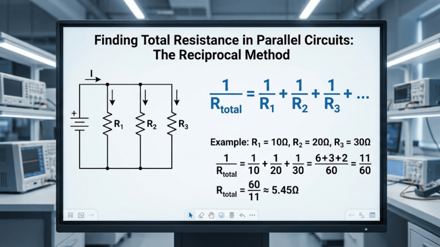
Finding total resistance in parallel circuits uses the reciprocal method: 1/R_total = 1/R₁ + 1/R₂ + 1/R₃ + …, then taking the reciprocal of the sum to get R_total. This calculation reflects the physical reality that parallel paths allow current to divide among multiple routes, reducing overall resistance—always resulting in a total resistance lower than the smallest individual resistor, opposite to the simple addition used in series circuits.
Introduction: When Current Has Multiple Paths
While series circuits offer current a single path—like a one-lane road—parallel circuits present multiple routes simultaneously, like a multi-lane highway where traffic can distribute across several lanes. This fundamental difference in circuit topology creates a dramatically different behavior: instead of resistances adding together, parallel resistances combine in a way that actually reduces total resistance.
This counterintuitive result surprises many beginners. How can adding more resistors reduce total resistance? The answer lies in understanding that each parallel path provides an additional route for current to flow. Just as opening more checkout lanes at a store increases the rate at which customers can pass through, adding parallel resistors increases the rate at which current can flow—which is the opposite of resistance.
The mathematical technique for calculating parallel resistance—the reciprocal method—reflects this physical reality. Instead of simple addition (as with series circuits), we work with reciprocals, which properly account for how multiple parallel paths reduce overall opposition to current flow.
Parallel circuits appear everywhere in practical electronics: power distribution systems where multiple devices connect to the same voltage source, current dividers that split current among different loads, redundant systems for reliability, resistor networks for fine-tuning values, and countless other applications. Understanding how to calculate parallel resistance is essential for analyzing and designing these circuits effectively.
This comprehensive guide will take you from the fundamental concepts through advanced applications. We’ll explore why the reciprocal method works, learn multiple calculation techniques including shortcuts for special cases, work through diverse practical examples, examine common mistakes, and develop the intuition needed to work confidently with parallel circuits. Whether you’re calculating the equivalent resistance of two resistors in parallel or analyzing complex multi-branch networks, this article provides the knowledge you need.
Let’s begin by understanding what makes a circuit “parallel” and why this configuration behaves so differently from series circuits.
What Defines a Parallel Circuit?
The Essential Characteristic: Common Voltage
A parallel circuit is defined by one fundamental property: all components share the same voltage across their terminals.
Visual analogy: Think of parallel resistors like multiple pipes connecting the same two water tanks. Each pipe experiences the same pressure difference (analogous to voltage), but water flow (analogous to current) divides among the pipes based on their size (analogous to resistance).
Technical definition: Components are in parallel when:
- They connect to the same two nodes (junction points)
- The voltage across each component is identical
- Current divides among the components based on their individual resistances
Contrast with series: In series circuits, components share the same current but have different voltages. In parallel circuits, components share the same voltage but have different currents.
Identifying Parallel Components in Circuits
Simple parallel circuit: Battery positive → splits to three resistor tops Three resistor bottoms → join together → Battery negative
All three resistors connect between the same two nodes (battery terminals), so they’re in parallel.
Mixed circuit example:
- Battery connects to Resistor A (series)
- After Resistor A, circuit splits into Resistor B and Resistor C (parallel to each other)
- After B and C, circuit returns through Resistor D (series)
Parallel components: Only Resistors B and C (they share common nodes) Series components: A is in series with the B-C parallel combination, and that combination is in series with D
Key insight: Components are parallel if you can trace from one component’s top terminal to another component’s top terminal without passing through any other components, AND you can do the same for the bottom terminals.
Parallel Connections in Physical Circuits
On a breadboard: Components plugged into the same two power rails are in parallel (each rail is a node, all components connect between the same two rails).
On a PCB: Components connected between the same two copper traces/pads are in parallel.
In a schematic: Components drawn side-by-side with their terminals connected to the same circuit nodes are in parallel. Look for common connection points.
In household wiring: All wall outlets in your home are wired in parallel to the circuit breaker panel. Each device can be turned on/off independently, and all receive the same voltage (120V in North America, 230V in Europe).
Why Current Divides in Parallel Circuits
This is a consequence of Kirchhoff’s Current Law (KCL) and Ohm’s Law working together:
KCL at the split node: Current entering the node must equal current leaving the node. If 3A enters and splits into three parallel branches, those branch currents must sum to 3A.
Ohm’s Law for each branch: Each resistor has the same voltage across it (V). Using I = V ÷ R, current through each resistor is determined by its resistance:
- Lower resistance → Higher current through that branch
- Higher resistance → Lower current through that branch
Example: 10V applied across two parallel resistors: 100Ω and 200Ω
Current through 100Ω: I₁ = 10V ÷ 100Ω = 0.1A = 100mA Current through 200Ω: I₂ = 10V ÷ 200Ω = 0.05A = 50mA Total current: I_total = 100mA + 50mA = 150mA
The 100Ω resistor (lower resistance) carries twice as much current as the 200Ω resistor.
The Reciprocal Method: Why Resistances Don’t Simply Add
The Fundamental Formula
For resistors in parallel, the reciprocal of total resistance equals the sum of reciprocals of individual resistances:
1/R_total = 1/R₁ + 1/R₂ + 1/R₃ + … + 1/Rₙ
After calculating the sum of reciprocals, take the reciprocal again to find R_total:
R_total = 1 / (1/R₁ + 1/R₂ + 1/R₃ + …)
Example: Two resistors in parallel: 100Ω and 200Ω
1/R_total = 1/100Ω + 1/200Ω = 0.01 + 0.005 = 0.015 R_total = 1 / 0.015 = 66.67Ω
Notice: R_total (66.67Ω) is less than both R₁ (100Ω) and R₂ (200Ω).
Why This Formula Makes Physical Sense
Conductance perspective: The reciprocal of resistance is conductance (G = 1/R), which measures how easily current flows (the opposite of resistance).
When you add parallel paths, conductances add: G_total = G₁ + G₂ + G₃ + …
This makes intuitive sense: each additional path increases the circuit’s ability to conduct current.
Since G = 1/R: 1/R_total = 1/R₁ + 1/R₂ + 1/R₃ + …
Current flow perspective: Each resistor carries current I = V/R. Total current is the sum: I_total = V/R₁ + V/R₂ + V/R₃ + … = V × (1/R₁ + 1/R₂ + 1/R₃ + …)
But also: I_total = V/R_total
Therefore: V/R_total = V × (1/R₁ + 1/R₂ + 1/R₃ + …)
Dividing both sides by V: 1/R_total = 1/R₁ + 1/R₂ + 1/R₃ + …
Mathematical Derivation Using KCL and Ohm’s Law
Given:
- Parallel circuit with voltage V applied across all resistors
- Resistors R₁, R₂, R₃
- Total current I_total from source
Step 1: Current through each resistor (Ohm’s Law) I₁ = V/R₁ I₂ = V/R₂ I₃ = V/R₃
Step 2: Total current (KCL at junction) I_total = I₁ + I₂ + I₃
Step 3: Substitute I_total = V/R₁ + V/R₂ + V/R₃
Step 4: Factor out V I_total = V × (1/R₁ + 1/R₂ + 1/R₃)
Step 5: Apply Ohm’s Law to total circuit I_total = V/R_total
Step 6: Equate V/R_total = V × (1/R₁ + 1/R₂ + 1/R₃)
Step 7: Divide by V 1/R_total = 1/R₁ + 1/R₂ + 1/R₃
This proves the reciprocal method mathematically.
Important Properties of Parallel Resistance
Property 1: Total resistance is always less than the smallest individual resistor R_total < R₁ and R_total < R₂ and R_total < R₃, etc.
Adding parallel resistors always decreases total resistance—the opposite of series!
Property 2: Equal resistors in parallel If all n resistors have the same value R: R_total = R/n
Example: Three 300Ω resistors in parallel: R_total = 300Ω/3 = 100Ω
Property 3: Dominant resistor effect If one resistor is much smaller than the others, it dominates the parallel combination.
Example: 10Ω in parallel with 10,000Ω: 1/R_total = 1/10 + 1/10,000 = 0.1 + 0.0001 = 0.1001 R_total ≈ 9.99Ω
The 10Ω resistor essentially determines the total (10,000Ω has minimal effect).
Property 4: Infinite parallel resistance from one open circuit If any branch is open (infinite resistance), it can be ignored in the calculation because 1/∞ = 0.
Step-by-Step: Calculating Parallel Resistance
The General Reciprocal Method
Step 1: Identify all parallel resistors Verify that resistors connect to the same two nodes (share the same voltage).
Step 2: List each resistor value Write down R₁, R₂, R₃, etc.
Step 3: Calculate reciprocals Find 1/R₁, 1/R₂, 1/R₃, etc.
Step 4: Add reciprocals Sum = 1/R₁ + 1/R₂ + 1/R₃ + …
Step 5: Take reciprocal of sum R_total = 1/Sum
Step 6: Verify result is less than smallest resistor A quick sanity check: R_total should be smaller than the smallest individual resistor.
Example 1: Two Resistors in Parallel
Given: R₁ = 1,000Ω (1kΩ) R₂ = 2,000Ω (2kΩ)
Step 1: Calculate reciprocals 1/R₁ = 1/1,000 = 0.001 1/R₂ = 1/2,000 = 0.0005
Step 2: Add reciprocals Sum = 0.001 + 0.0005 = 0.0015
Step 3: Take reciprocal R_total = 1/0.0015 ≈ 666.67Ω
Verification: 666.67Ω < 1,000Ω ✓ (less than smallest resistor)
Check with current: If V = 10V applied: I₁ = 10V/1kΩ = 10mA I₂ = 10V/2kΩ = 5mA I_total = 15mA
R_total = V/I_total = 10V/0.015A = 666.67Ω ✓
Example 2: Three Resistors in Parallel
Given: R₁ = 100Ω R₂ = 200Ω R₃ = 300Ω
Calculation: 1/R_total = 1/100 + 1/200 + 1/300 1/R_total = 0.01 + 0.005 + 0.00333… 1/R_total = 0.01833… R_total = 1/0.01833… ≈ 54.55Ω
Verification: 54.55Ω < 100Ω ✓ (less than smallest resistor)
Example 3: Four Equal Resistors in Parallel
Given: Four 1,000Ω (1kΩ) resistors in parallel
Using the equal resistor formula: R_total = R/n = 1,000Ω/4 = 250Ω
Using the general reciprocal method: 1/R_total = 1/1,000 + 1/1,000 + 1/1,000 + 1/1,000 1/R_total = 4/1,000 = 0.004 R_total = 1/0.004 = 250Ω ✓
For equal resistors, the shortcut is much faster!
Example 4: Mixed Units
Given: R₁ = 1.5kΩ R₂ = 470Ω R₃ = 22kΩ
Step 1: Convert to consistent units (ohms) R₁ = 1,500Ω R₂ = 470Ω R₃ = 22,000Ω
Step 2: Calculate 1/R_total = 1/1,500 + 1/470 + 1/22,000 1/R_total = 0.000667 + 0.002128 + 0.000045 1/R_total = 0.002840 R_total ≈ 352Ω
Observation: R₂ (470Ω) dominates because it’s much smaller than the others. The result (352Ω) is close to but less than 470Ω.
Example 5: Very Dissimilar Values
Given: R₁ = 10Ω R₂ = 1,000,000Ω (1MΩ)
Calculation: 1/R_total = 1/10 + 1/1,000,000 1/R_total = 0.1 + 0.000001 1/R_total = 0.100001 R_total ≈ 9.9999Ω
Key insight: The 1MΩ resistor has virtually no effect. When resistors differ by orders of magnitude, the smallest one dominates the parallel combination.
Practical rule: If one resistor is 100× smaller than another, you can often ignore the larger one in rough calculations.
Shortcuts and Special Cases
The Product-Over-Sum Formula (Two Resistors Only)
For exactly two resistors in parallel, there’s a convenient shortcut:
R_total = (R₁ × R₂) / (R₁ + R₂)
This is often called the “product over sum” formula.
Example: R₁ = 100Ω, R₂ = 150Ω
R_total = (100 × 150) / (100 + 150) R_total = 15,000 / 250 R_total = 60Ω
Verification using reciprocal method: 1/R_total = 1/100 + 1/150 = 0.01 + 0.00667 = 0.01667 R_total = 1/0.01667 = 60Ω ✓
When to use: Only for exactly two resistors. For three or more, use the general reciprocal method.
Equal Resistors Formula
For n identical resistors of value R in parallel:
R_total = R / n
Examples:
- Two 100Ω resistors: R_total = 100Ω/2 = 50Ω
- Five 1kΩ resistors: R_total = 1kΩ/5 = 200Ω
- Ten 470Ω resistors: R_total = 470Ω/10 = 47Ω
Why this works: Each resistor contributes equally, and n equal current paths reduce resistance by factor of n.
Two Equal Resistors: The Half Rule
Special case of equal resistors formula:
Two equal resistors in parallel: R_total = R/2
Examples:
- Two 1kΩ resistors: R_total = 500Ω
- Two 220Ω resistors: R_total = 110Ω
This is the most common parallel calculation in electronics!
Approximation for Dissimilar Values
When one resistor is much smaller (10× or more) than others:
R_total ≈ R_smallest
Example: 10Ω in parallel with 500Ω and 1kΩ:
Exact calculation: 1/R_total = 1/10 + 1/500 + 1/1,000 = 0.1 + 0.002 + 0.001 = 0.103 R_total ≈ 9.71Ω
Approximation: R_total ≈ 10Ω (smallest resistor)
Error: About 3%, acceptable for many rough calculations.
Calculator Techniques
Method 1: Using reciprocal button (1/x)
- Enter R₁, press 1/x, store in memory (M+)
- Enter R₂, press 1/x, add to memory (M+)
- Enter R₃, press 1/x, add to memory (M+)
- Recall memory (MR), press 1/x
- Result is R_total
Method 2: Running calculation
- Calculate 1/R₁, write down
- Calculate 1/R₂, add to previous
- Calculate 1/R₃, add to running sum
- Take reciprocal of final sum
Method 3: Spreadsheet formula In a spreadsheet: =1/(1/A1 + 1/A2 + 1/A3) Where A1, A2, A3 contain resistor values.
Practical Applications of Parallel Resistance
Application 1: Current Dividers
Purpose: Split current among multiple paths in controlled ratios.
Example: 10A current needs to split between two loads:
- Load A should receive 7A
- Load B should receive 3A
Using parallel resistors as current divider: Current divides inversely proportional to resistance.
If R_A and R_B are in parallel: I_A/I_B = R_B/R_A (inverse relationship)
Want: I_A/I_B = 7A/3A ≈ 2.33
Therefore: R_B/R_A = 2.33, or R_B = 2.33 × R_A
Choose: R_A = 10Ω, then R_B = 23.3Ω (use 22Ω standard value)
Verification: R_total = (10 × 22)/(10 + 22) ≈ 6.88Ω If 10V applied (to get ~10A total at 1Ω load resistance): I_A = 10V/10Ω = 1A… wait, this needs total system design, not just the divider!
Actually for pure current division with 10A total: I_A = I_total × (R_B/(R_A + R_B)) = 10A × (22/(10+22)) ≈ 6.88A I_B = 10A × (10/(10+22)) ≈ 3.13A
Close to target 7A and 3A (adjusting R values would fine-tune).
Application 2: Creating Custom Resistance Values
Problem: Need 75Ω but only have standard values (82Ω, 68Ω, 100Ω, 150Ω, 220Ω available).
Solution using parallel combination:
Try 1: 150Ω in parallel with 150Ω = 75Ω (exact!) Need two 150Ω resistors.
Try 2: If only one of each value available, try: 100Ω parallel with 220Ω: R = (100 × 220)/(100 + 220) = 22,000/320 ≈ 68.75Ω (close)
Try 3: Could use series-parallel combination, but that’s more complex.
Application 3: Reducing Resistance for Higher Current
Problem: Have 1kΩ resistor but need 100Ω to limit current in a circuit.
Solution: Use 10 resistors (all 1kΩ) in parallel: R_total = 1kΩ/10 = 100Ω
Power distribution advantage: If circuit dissipates 10W total:
- Single 100Ω resistor: Must handle 10W (requires large, expensive resistor)
- Ten 1kΩ resistors in parallel: Each handles 1W (can use standard 1W resistors)
Application 4: Redundancy and Reliability
Purpose: If one component fails open, others continue functioning.
Example: Critical circuit needs 500Ω resistance with high reliability.
Design: Use four 2kΩ resistors in parallel: Normal: R = 2kΩ/4 = 500Ω If one fails open: R = 2kΩ/3 ≈ 667Ω (33% increase, circuit may still function) If two fail: R = 2kΩ/2 = 1kΩ (100% increase, circuit operates at reduced performance)
Comparison to series: In series, one open resistor breaks entire circuit (0% functionality). In parallel, partial functionality remains even with failures.
Application 5: LED Parallel Strings (with caution!)
Scenario: Want to drive multiple LEDs from one supply without complex current control.
WARNING: LEDs in parallel without individual current limiting is risky because slight V_f differences cause current imbalance.
Safer approach: Parallel LED branches, each with its own current-limiting resistor:
Branch 1: LED + 330Ω resistor Branch 2: LED + 330Ω resistor
Branch 3: LED + 330Ω resistor
Each branch is independent. Parallel combination of three 330Ω resistors: R_total ≈ 110Ω (approximate equivalent for load calculation)
This is safer than three bare LEDs in parallel.
Application 6: Input Impedance Adjustment
Purpose: Modify input impedance of a circuit for signal matching.
Example: Amplifier has 100kΩ input impedance, but signal source works best with 50kΩ load.
Solution: Add 100kΩ resistor in parallel with input: R_total = (100kΩ × 100kΩ)/(100kΩ + 100kΩ) = 50kΩ
Now source sees 50kΩ load impedance.
Trade-off: Parallel resistor dissipates power and forms voltage divider (reduces signal by 50%). Need to account for this in design.
Common Mistakes and How to Avoid Them
Mistake 1: Using Series Formula for Parallel Circuits
Error: Adding resistors directly: R_total = R₁ + R₂ (this is series formula!)
Example of error: 100Ω and 200Ω in parallel, calculated as: 100Ω + 200Ω = 300Ω (WRONG!)
Correct: R_total = (100 × 200)/(100 + 200) = 66.67Ω
How to avoid:
- Always check circuit topology first
- Ask: “Same voltage across components?” → Parallel
- Ask: “Same current through components?” → Series
- Remember: Parallel total is always LESS than smallest resistor
Mistake 2: Forgetting to Take Final Reciprocal
Error: Calculating 1/R₁ + 1/R₂ + 1/R₃ and stopping there.
Example of error: 100Ω, 200Ω, 300Ω in parallel: 1/100 + 1/200 + 1/300 = 0.01833… (WRONG—this is 1/R_total, not R_total!)
Correct: 1/R_total = 0.01833… R_total = 1/0.01833… ≈ 54.55Ω
How to avoid:
- Remember: The formula has TWO reciprocal steps
- First: Take reciprocals and add them
- Second: Take reciprocal of the sum
- Check: Result should be less than smallest resistor
Mistake 3: Calculator Entry Errors
Error: Incorrect use of calculator parentheses or order of operations.
Example of error: Trying to calculate (100 × 200)/(100 + 200) on calculator: Entering: 100 × 200 ÷ 100 + 200 = 400 (WRONG due to order of operations!)
Correct calculator entry: (100 × 200) ÷ (100 + 200) = 66.67 or 100 × 200 = [M+], 100 + 200 = , [MR] ÷ [answer]
How to avoid:
- Use parentheses explicitly
- Verify intermediate results make sense
- Double-check with alternative calculation method
Mistake 4: Unit Inconsistency
Error: Mixing kΩ and Ω without converting.
Example of error: 1kΩ in parallel with 500Ω: 1/R = 1/1 + 1/500 = 1.002 (treating 1kΩ as 1 instead of 1,000)
Correct: Convert to ohms: 1,000Ω and 500Ω 1/R = 1/1,000 + 1/500 = 0.001 + 0.002 = 0.003 R = 333.33Ω
How to avoid:
- Always convert to same units first
- Work in base unit (ohms) for calculations
- Convert to convenient units only for final answer
Mistake 5: Misidentifying Parallel Sections
Error: Assuming physically adjacent components are parallel.
Example: On a breadboard, two resistors in the same row but spanning different sets of holes might not be parallel if the row has a gap in the middle.
How to avoid:
- Trace the electrical connections, not physical proximity
- Verify both ends of components connect to same nodes
- Use multimeter in continuity mode to verify connections
- Study schematic carefully for junction points
Mistake 6: Ignoring Component Tolerances
Error: Calculating exact parallel resistance without considering real component variations.
Example: Two “100Ω” resistors (±5% tolerance) in parallel:
Nominal calculation: 100Ω/2 = 50Ω
Worst case: Both at maximum: 105Ω/2 = 52.5Ω Both at minimum: 95Ω/2 = 47.5Ω
Range: 47.5Ω to 52.5Ω (±5% of 50Ω)
The percentage tolerance is preserved, but you must account for it in critical circuits.
How to avoid:
- Consider tolerance in sensitive designs
- Use precision resistors (±1% or ±0.1%) when needed
- Measure actual values for critical applications
- Design circuits robust to component variation
Mistake 7: Wrong Formula for Multiple Resistors
Error: Using product-over-sum formula for three or more resistors.
Example of error: Three resistors 100Ω, 200Ω, 300Ω: Wrong: (100 × 200 × 300)/(100 + 200 + 300) = 10,000 (incorrect formula application!)
Correct: Use reciprocal method: 1/R = 1/100 + 1/200 + 1/300 = 0.01833 R = 54.55Ω
How to avoid:
- Remember: Product-over-sum is ONLY for exactly two resistors
- For three or more: Use reciprocal method
- For equal resistors: Use R/n shortcut
Advanced Topics: Parallel Resistance in Complex Scenarios
Parallel Resistance in AC Circuits
For pure resistors in AC: Same parallel formulas apply as in DC.
With impedance (capacitors, inductors): Use complex impedance Z instead of resistance R:
1/Z_total = 1/Z₁ + 1/Z₂ + 1/Z₃ + …
Example: Resistor (100Ω) in parallel with capacitor (j50Ω reactance):
1/Z_total = 1/100 + 1/(-j50) 1/Z_total = 0.01 + j0.02 Z_total = 1/(0.01 + j0.02)
Converting: |Z_total| ≈ 44.7Ω at -63.4° phase
This involves complex number arithmetic, beyond basic DC analysis.
Parallel Resistance with Current Sources
Current sources: Provide constant current regardless of voltage.
Example: 2A current source in parallel with 100Ω resistor:
The current source forces 2A through the parallel combination. Voltage across both: V = I × R = 2A × 100Ω = 200V (!)
Key insight: Current sources in parallel add their currents. Two 2A current sources in parallel deliver 4A total.
Mixed with resistors: Current source (2A) parallel with resistor (100Ω) parallel with another resistor (200Ω):
Resistor combination: R = (100 × 200)/(100 + 200) = 66.67Ω Voltage: V = 2A × 66.67Ω = 133.3V Current through 100Ω: I = 133.3V/100Ω = 1.33A Current through 200Ω: I = 133.3V/200Ω = 0.67A Total: 1.33A + 0.67A = 2A ✓ (from current source)
Thevenin and Norton Equivalents
Norton equivalent resistance: The parallel resistance as seen from a pair of terminals.
Finding Norton resistance:
- Remove all independent sources (voltage sources → short, current sources → open)
- Calculate resistance between the terminals
- This often involves parallel combinations
Example: Circuit with 100Ω and 200Ω in parallel, viewed from terminals: R_Norton = (100 × 200)/(100 + 200) = 66.67Ω
This represents the circuit’s output impedance.
Parallel Resistors with Internal Resistance
Real components: Have parasitic resistances.
Example: Two batteries (1.5V each with 0.5Ω internal resistance) in parallel:
Voltage sources in parallel: Both provide 1.5V (ideal case)
Internal resistances in parallel: R_internal = (0.5Ω × 0.5Ω)/(0.5Ω + 0.5Ω) = 0.25Ω
Combined battery: Voltage: 1.5V Internal resistance: 0.25Ω (lower than single battery)
Result: Can deliver higher current with less voltage drop than single battery.
Temperature Effects on Parallel Resistance
Temperature coefficient: Resistance changes with temperature.
Example: Two 1kΩ resistors in parallel, both with +50ppm/°C temperature coefficient:
At 25°C: R_total = 1kΩ/2 = 500Ω
At 75°C (50°C rise): Each resistor: 1,000Ω × (1 + 50×10⁻⁶ × 50) = 1,002.5Ω R_total = 1,002.5Ω/2 = 501.25Ω
Change: 1.25Ω increase (0.25%)
Key insight: Parallel combination’s temperature coefficient equals individual component temperature coefficient (if all components have same coefficient).
Dynamic Resistance and Nonlinear Components
Diodes, LEDs, transistors: Have nonlinear I-V curves, so “resistance” varies with operating point.
Parallel diodes: Don’t simply add reciprocals because resistance isn’t constant.
Instead, analyze using diode equations or graphically using I-V curves.
Approximation: For small signal analysis around an operating point, can define dynamic resistance and use parallel formulas locally.
Comparison Table: Series vs. Parallel Resistance Calculations
| Aspect | Series Resistance | Parallel Resistance |
|---|---|---|
| Basic Formula | R_total = R₁ + R₂ + R₃ + … | 1/R_total = 1/R₁ + 1/R₂ + 1/R₃ + … |
| Calculation Method | Direct addition | Reciprocal addition, then invert |
| Two equal resistors (R) | R_total = 2R | R_total = R/2 |
| Effect of adding resistors | Increases total R | Decreases total R |
| Result vs. individual R | Always greater than largest | Always less than smallest |
| Current through components | Same through all | Divides among components |
| Voltage across components | Divides among components | Same across all |
| Mathematical complexity | Very simple (addition) | Moderate (reciprocals) |
| Common shortcuts | None needed (already simple) | Product-over-sum (2 resistors), R/n (equal resistors) |
| Dominant component | Largest resistor dominates | Smallest resistor dominates |
| Typical applications | Voltage dividers, current limiting | Current dividers, reduced resistance |
| Failure mode effect | One open = total circuit open | One open = minimal effect (others still work) |
| Power distribution | Unequal (largest R gets most) | Unequal (smallest R gets most) |
| Design strategy | Use to increase R or divide V | Use to decrease R or divide I |
Practical Measurement and Verification
Measuring Parallel Resistance
Method 1: Direct resistance measurement
- Disconnect parallel combination from circuit
- Measure resistance across the combination with ohmmeter
- Compare to calculated value
Expected agreement: Within component tolerance
Example: Two 100Ω ±5% resistors in parallel: Calculated nominal: 50Ω Measurement range: 47.5Ω to 52.5Ω (accounting for tolerance)
Verification Using Current Distribution
Method 2: Measure individual branch currents
With circuit powered:
- Measure current through each parallel branch
- Sum the currents
- Compare to total current from source (should match per KCL)
- Calculate R_total = V/I_total
- Compare calculated R_total to theoretical value
Example: Two resistors in parallel across 10V: Measure I₁ = 95mA, I₂ = 47mA I_total = 142mA R_total = 10V/0.142A ≈ 70.4Ω
If theoretical calculation was 70Ω, this verifies the circuit (within measurement error).
Troubleshooting Parallel Circuits
Problem: Measured R_total higher than expected
Possible causes:
- One or more resistors have increased in value (damage, heat)
- Poor connection adding resistance
- Wrong resistor values installed
- One branch is partially open
Diagnosis: Measure each resistor individually to identify which one is out of spec.
Problem: Measured R_total much lower than expected
Possible causes:
- Solder bridge creating additional parallel path
- Wrong (lower) resistor value installed
- Short circuit somewhere
Diagnosis: Inspect for solder bridges, verify resistor values, check for shorts with continuity tester.
Problem: Current imbalance in parallel branches
Expected: Current divides inversely proportional to resistance.
If measured currents don’t match: Check individual resistor values (they may not be as marked), verify good connections in each branch.
Design Strategies Using Parallel Resistance
Strategy 1: Fine-Tuning Resistance Values
Problem: Need 73Ω resistance, but standard values are 68Ω and 75Ω.
Solution 1: Parallel combination approaching target: Try 150Ω || 150Ω = 75Ω (too high) Try 220Ω || 220Ω = 110Ω (too high) Try 150Ω || 330Ω = (150×330)/(150+330) ≈ 103Ω (too high)
Better solution: Use series-parallel combination: 68Ω in series with small parallel network to add 5Ω
Solution 2: Parallel of higher values: Try 180Ω || 270Ω = (180×270)/(180+270) ≈ 108Ω (too high) Try 150Ω || 180Ω = (150×180)/(150+180) ≈ 81.8Ω (getting closer)
Practical approach: 73Ω is close enough to 75Ω for most applications. Use 75Ω unless precision is critical.
Strategy 2: Power Distribution
Problem: Need 10Ω resistance to dissipate 20W.
Single resistor option: 10Ω 20W resistor (large, expensive, may overheat)
Parallel distribution option: Use four 40Ω 5W resistors in parallel: R_total = 40Ω/4 = 10Ω ✓ P_each = 20W/4 = 5W ✓
Advantages:
- Smaller, cheaper components
- Better heat distribution
- Redundancy (if one fails open, others continue)
Strategy 3: Current Capacity Increase
Problem: PCB trace can carry 1A, but circuit needs 3A.
Solution: Run three parallel traces: R_trace_single = 0.05Ω (example) R_parallel = 0.05Ω/3 ≈ 0.0167Ω
Each trace carries: 3A/3 = 1A (within rating)
Same strategy works for:
- Wire bundles (multiple wires in parallel)
- Contact fingers (multiple parallel contacts)
- PCB vias (multiple vias in parallel for high current)
Strategy 4: Impedance Matching
Problem: Signal source has 50Ω output impedance. Load is 75Ω. Need to match.
Parallel resistor solution: Add resistor R in parallel with 75Ω load to create equivalent 50Ω:
50Ω = (75Ω × R)/(75Ω + R) 50(75 + R) = 75R 3750 + 50R = 75R 3750 = 25R R = 150Ω
Verification: (75 × 150)/(75 + 150) = 11,250/225 = 50Ω ✓
Trade-off: Power loss in matching resistor, but proper impedance matching achieved.
Strategy 5: Adjustable Resistance
Problem: Need variable resistance from 50Ω to 200Ω.
Solution: Fixed resistor in parallel with potentiometer.
Analysis: Want R_min = 50Ω when pot at minimum (0Ω): 50Ω = (R_fixed × 0)/(R_fixed + 0) → This doesn’t work (gives 0Ω)
Revised approach: Use series-parallel combination or reconsider range.
Better solution for this range: Use 200Ω potentiometer directly, or Use 150Ω fixed + 50Ω pot in series (gives 150-200Ω range)
For parallel adjustable: Works better when you want to adjust downward from a fixed value.
Example: 100Ω fixed || variable pot (0-100Ω) gives range from 50Ω to 100Ω.
Practical Circuit Examples
Example 1: Dual-Supply Current Sensing
Scenario: Monitor current from two power supplies feeding a common load.
Circuit:
- Supply A: 12V
- Supply B: 12V
- Load: 2Ω
- Shunt resistor in each supply line: 0.1Ω each
Analysis: Both supplies in parallel (both 12V sources): Current divides based on total resistance in each path.
Path A: 0.1Ω (shunt) in series with load’s half = 0.1Ω + 1Ω = 1.1Ω Path B: 0.1Ω (shunt) in series with load’s half = 0.1Ω + 1Ω = 1.1Ω
Equal paths, so current splits equally.
Total parallel R = 1.1Ω || 1.1Ω = 0.55Ω Total current = 12V/0.55Ω ≈ 21.8A Current per supply ≈ 10.9A
Voltage across each shunt: V = 10.9A × 0.1Ω ≈ 1.09V (measurable for current monitoring)
Example 2: LED Array Power Calculation
Scenario: 12 LEDs arranged as 4 parallel branches of 3 series LEDs each.
Given:
- Supply: 12V
- LED V_f: 2V
- Desired current per branch: 20mA
- Current-limiting resistor per branch: R = ?
Per-branch analysis (series): 3 LEDs × 2V = 6V Resistor voltage: 12V – 6V = 6V R = 6V/0.020A = 300Ω (use 330Ω standard value)
Actual current per branch: I = 6V/330Ω ≈ 18.2mA
Parallel combination of 4 branches: Each branch: 330Ω R_total = 330Ω/4 = 82.5Ω (equivalent resistance of all 4 current-limiting resistors in parallel)
Total current: I_total = 4 × 18.2mA ≈ 72.8mA
Power supply requirement: 12V at 73mA minimum
Example 3: Voltage Reference with Parallel Trim
Scenario: Create precise 5.000V reference using 5.6V Zener diode with parallel resistor for trimming.
Given:
- Zener voltage: 5.6V nominal (may vary 5.4V to 5.8V)
- Target: 5.000V
- Adjustment method: Parallel resistor creates voltage divider with Zener dynamic resistance
This is complex, requires understanding of Zener dynamic resistance, but illustrates parallel resistance in precision circuits.
Simplified approach: Measure actual Zener voltage. If 5.65V, need to reduce by 0.65V (11.5% reduction).
Use voltage divider after Zener, or use precision voltage reference IC instead of Zener + parallel trim.
Conclusion: Mastering Parallel Resistance Calculations
Understanding parallel resistance calculations opens the door to analyzing and designing a vast array of electronic circuits. While the reciprocal method requires more mathematical steps than the simple addition used for series circuits, it accurately reflects the physical reality that parallel paths reduce total resistance by providing multiple routes for current flow.
Key Takeaways
The fundamental principle: Parallel resistances combine through the reciprocal formula: 1/R_total = 1/R₁ + 1/R₂ + 1/R₃ + …, then R_total = 1/(sum of reciprocals).
Essential property: Total parallel resistance is always less than the smallest individual resistor—the opposite of series circuits where total resistance is always greater than any individual component.
Practical shortcuts:
- Two resistors: Product-over-sum formula (R₁×R₂)/(R₁+R₂)
- Equal resistors: R_total = R/n
- Very different values: Smallest resistor dominates
Current division: In parallel circuits, current divides among branches inversely proportional to resistance—lower resistance carries more current.
Real-World Applications
From current dividers to power distribution, from creating custom resistance values to improving circuit reliability through redundancy, parallel resistance appears throughout practical electronics. Understanding how to calculate and apply these principles enables you to:
- Design circuits that split current appropriately
- Calculate equivalent resistance of complex networks
- Size components for adequate power handling
- Create precise resistance values from standard parts
- Troubleshoot circuits with unexpected behavior
Integration with Broader Circuit Analysis
Parallel resistance calculations don’t exist in isolation—they integrate seamlessly with:
- Ohm’s Law: V = I × R applies to each branch and the total combination
- Kirchhoff’s Current Law: Current splits among parallel branches, summing at nodes
- Power analysis: Each resistor dissipates power based on current through it
- Series-parallel networks: Real circuits combine both configurations
Moving Forward
Now that you understand parallel resistance:
- Practice extensively: Work through problems with different numbers of resistors and varied values
- Verify with measurements: Build parallel circuits and confirm calculations match reality
- Study series-parallel combinations: Learn to analyze circuits with mixed configurations
- Apply to real designs: Use parallel resistance in current dividers, power distribution, and custom value creation
- Explore advanced topics: AC impedance, complex networks, and optimization strategies
The Complementary Pair
Series and parallel resistances are complementary concepts:
- Series: R_total = R₁ + R₂ + R₃ + … (increases total R)
- Parallel: 1/R_total = 1/R₁ + 1/R₂ + 1/R₃ + … (decreases total R)
Master both, and you can analyze any resistive network, no matter how complex.
Final Thoughts
The reciprocal method for parallel resistance may seem more complicated than series addition, but with practice, it becomes second nature. The extra mathematical steps are simply reflecting the physical reality: multiple parallel paths provide more routes for current, reducing total opposition to flow.
Whether you’re calculating the resistance of two resistors in parallel for a simple current divider or analyzing a complex power distribution network with dozens of parallel branches, the same fundamental principle applies. Each calculation reinforces your understanding of how parallel circuits behave and why resistance decreases when you add parallel paths.
From your first experiments with parallel resistors on a breadboard to sophisticated circuit designs optimizing power distribution and current division, parallel resistance calculations will be an essential tool in your electronics toolkit.
The journey to electronics mastery requires understanding both the simple (series) and the slightly complex (parallel). You’ve now mastered both fundamental building blocks. Everything else in resistive network analysis builds on these foundations.
1/R_total = 1/R₁ + 1/R₂ + 1/R₃ + …
Reciprocal method. Universal application. Foundation of parallel circuit analysis.