Using Ohm’s Law to solve real circuit problems involves systematically identifying known values (voltage, current, or resistance), selecting the appropriate formula variation (V = I × R, I = V ÷ R, or R = V ÷ I), performing calculations with proper unit conversions, and verifying results make physical sense. This practical application transforms the theoretical V = I × R relationship into a powerful problem-solving tool for designing LED circuits, selecting components, troubleshooting failures, calculating power requirements, and optimizing circuit performance in everyday electronics projects.
Introduction: From Theory to Practice
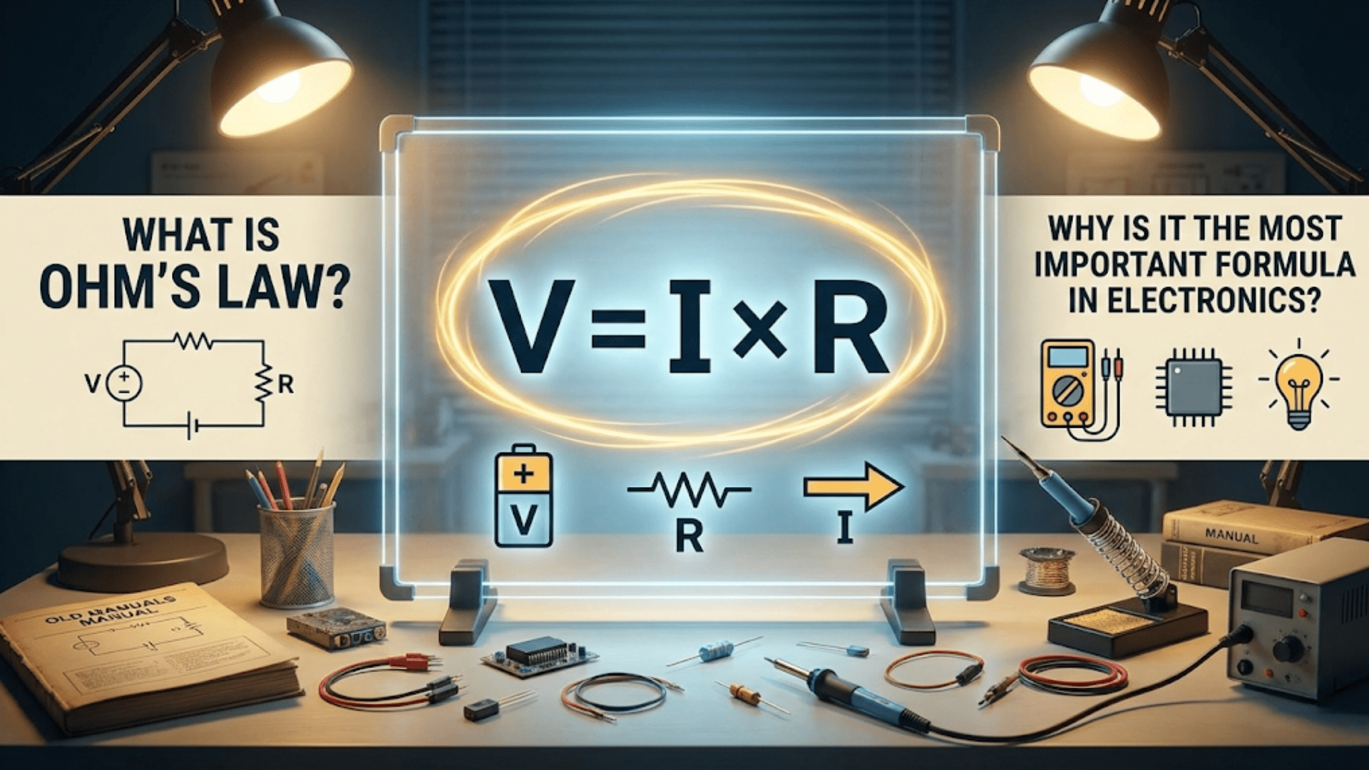
Understanding Ohm’s Law as a formula is one thing; applying it to solve actual electronics problems is entirely another. While V = I × R might look simple on paper, real-world circuits present complexities that textbooks often gloss over: multiple components interacting, standard component values that don’t match calculated ideals, safety margins to consider, and the need to verify that your theoretical calculations will work in practice.
This article bridges the gap between theory and practice. Rather than abstract problems with perfect numbers, we’ll tackle the kinds of challenges you’ll actually encounter when building circuits, troubleshooting equipment, or designing projects. These aren’t contrived examples designed to produce clean answers—they’re realistic scenarios that require you to think through multiple considerations, make engineering judgments, and sometimes accept approximate solutions.
Whether you’re a hobbyist building your first Arduino project, a student working on electronics labs, a technician troubleshooting industrial equipment, or an engineer designing new products, you’ll face situations where Ohm’s Law provides the answers you need. The key is knowing how to set up the problem correctly, what simplifying assumptions are reasonable, and how to interpret your results in the context of real components and practical constraints.
Throughout this guide, we’ll work through diverse examples organized by common problem types: designing circuits from scratch, selecting the right components, troubleshooting failures, optimizing performance, and ensuring safety. Each example includes not just the mathematical solution, but also the reasoning process, practical considerations, and tips that experienced engineers use to work efficiently and avoid common pitfalls.
By the end of this article, you won’t just know Ohm’s Law—you’ll know how to wield it as the practical problem-solving tool it’s meant to be. You’ll develop the engineering intuition that separates those who can recite formulas from those who can actually build working circuits.
Let’s dive into the real world of electronics problem-solving.
Problem Type 1: Designing LED Circuits
Example 1.1: Basic LED Current Limiting
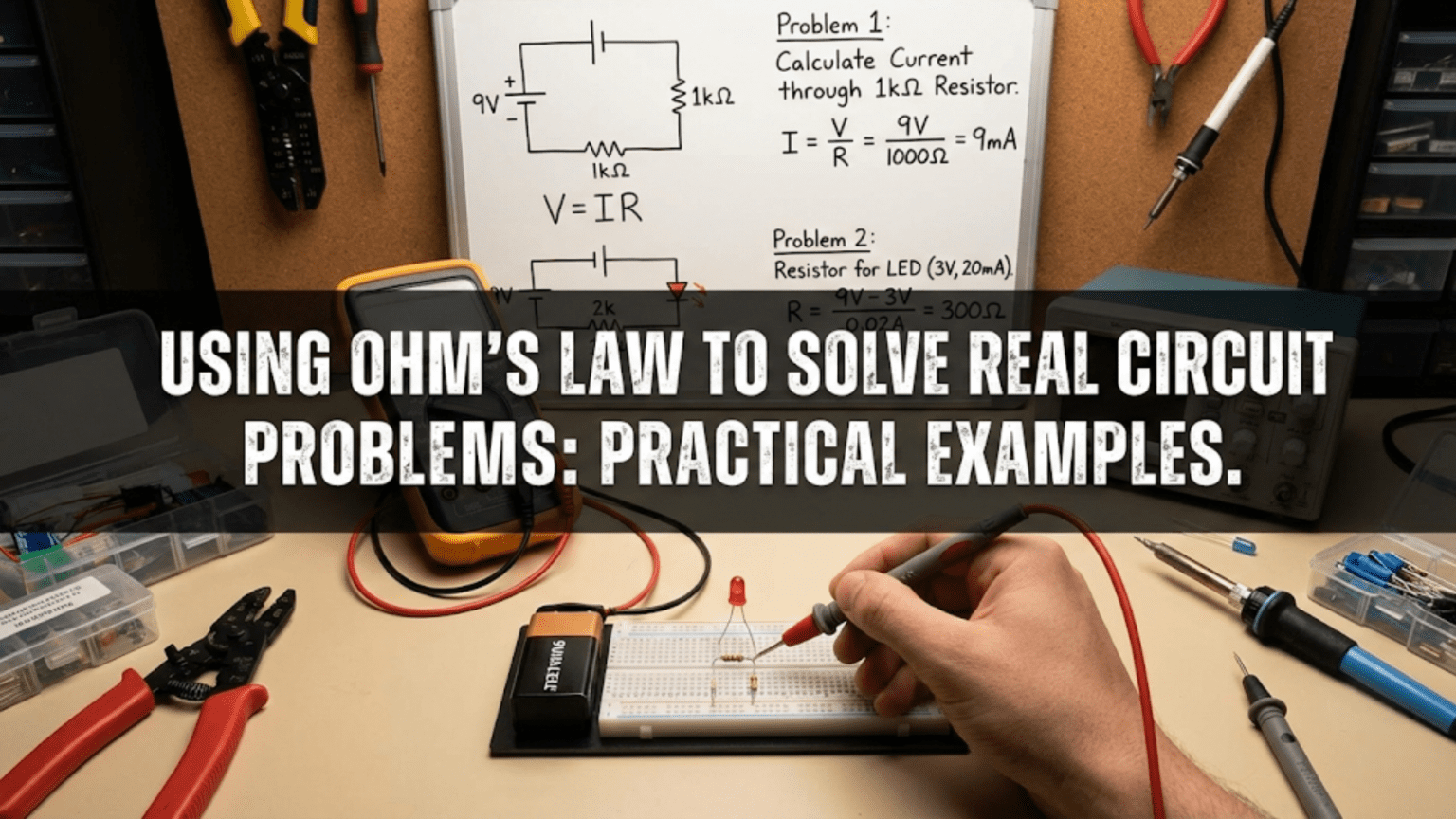
The Problem: You want to power a standard red LED from a 9V battery. The LED datasheet specifies a forward voltage (V_f) of 2.0V and maximum continuous current of 20 mA. What resistor do you need?
Step 1: Understand what’s happening When the LED is conducting, it will drop approximately 2V across its terminals. The resistor must drop the remaining voltage (9V – 2V = 7V) and limit current to a safe value for the LED.
Step 2: Identify known values
- Total voltage (V_total) = 9V
- LED forward voltage (V_f) = 2.0V
- Desired LED current (I_LED) = 20 mA = 0.020 A
- Voltage across resistor (V_R) = V_total – V_f = 9V – 2.0V = 7V
Step 3: Apply Ohm’s Law R = V ÷ I R = 7V ÷ 0.020A R = 350Ω
Step 4: Select a standard resistor value 350Ω isn’t a standard resistor value in the E12 or E24 series. The nearest standard values are 330Ω and 390Ω. Which should you choose?
Engineering decision: Use 390Ω because it’s the next larger value, which will result in slightly less current through the LED, making it safer. Never round down with current-limiting resistors.
Step 5: Verify the actual current With a 390Ω resistor: I = V ÷ R = 7V ÷ 390Ω ≈ 0.0179A ≈ 18 mA
This is below the 20 mA maximum, so it’s safe. The LED will be slightly dimmer than at 20 mA, but still quite visible.
Step 6: Check power dissipation P = V × I = 7V × 0.0179A ≈ 0.125W
A standard 1/4 watt (0.25W) resistor is sufficient, with comfortable safety margin.
Practical tip: For most hobby applications with single LEDs, a 330Ω or 470Ω resistor works well with voltages from 5V to 12V. Keep a stock of these values for quick LED circuits.
Example 1.2: Multiple LEDs in Series
The Problem: You want to create a decorative string of three white LEDs in series, powered by a 12V supply. Each LED has V_f = 3.2V and you want 15 mA through the string. What resistor do you need?
Step 1: Calculate total LED voltage drop With three LEDs in series, the voltages add: V_LEDs = 3 × 3.2V = 9.6V
Step 2: Calculate resistor voltage V_R = V_total – V_LEDs = 12V – 9.6V = 2.4V
Step 3: Calculate required resistance R = V ÷ I = 2.4V ÷ 0.015A = 160Ω
Step 4: Select standard value The nearest standard value is 150Ω or 180Ω. Using 180Ω: I = 2.4V ÷ 180Ω ≈ 13.3 mA
Step 5: Check power dissipation P = V × I = 2.4V × 0.0133A ≈ 0.032W
A 1/4 watt resistor is fine.
Important consideration: This circuit has a problem! With 12V input and 9.6V consumed by the LEDs, you only have 2.4V of “headroom” for the resistor. If your 12V supply actually delivers 11.5V (common for partially discharged batteries or regulated supplies under load), the LED voltage becomes: V_R = 11.5V – 9.6V = 1.9V I = 1.9V ÷ 180Ω ≈ 10.6 mA
The LEDs will be noticeably dimmer. For better performance, use a higher voltage supply (15V or more) or fewer LEDs in series.
Design rule: For LED strings, aim for at least 20-30% voltage headroom beyond the LED forward voltage drops to ensure consistent brightness.
Example 1.3: Parallel LED Branches
The Problem: You want to light six LEDs from a 5V supply. To increase reliability, you decide to use three parallel branches of two LEDs each, with each branch having its own current-limiting resistor. Each LED has V_f = 2.0V, and you want 15 mA per branch. What resistor value do you need, and what total current will your circuit draw?
Step 1: Analyze one branch Each branch has two LEDs in series: V_LEDs = 2 × 2.0V = 4.0V V_R = 5V – 4.0V = 1.0V
Step 2: Calculate resistor for one branch R = V ÷ I = 1.0V ÷ 0.015A ≈ 67Ω
Step 3: Select standard value Nearest standard values: 68Ω (perfect!) or 75Ω Using 68Ω: I = 1.0V ÷ 68Ω ≈ 14.7 mA (close enough)
Step 4: Calculate total current With three identical branches: I_total = 3 × 14.7 mA ≈ 44 mA
Step 5: Verify power supply capability Your 5V supply must provide at least 44 mA. Most USB ports provide 500 mA, so this is fine. A small 78L05 voltage regulator (100 mA max) would also work.
Step 6: Check resistor power dissipation Per resistor: P = V × I = 1.0V × 0.0147A ≈ 0.015W 1/4 watt resistors are adequate.
Why parallel branches with individual resistors? This design is more reliable than a single resistor for all six LEDs. If one LED fails open, only one branch goes dark instead of all six. If one LED fails shorted, only its resistor limits current (protecting that branch), rather than overcurrent damaging all LEDs.
Problem Type 2: Power Supply and Voltage Regulation
Example 2.1: Voltage Regulator Current Requirements
The Problem: You’re designing a circuit that will run from a 9V battery through a 5V voltage regulator. Your circuit contains an Arduino (drawing approximately 50 mA), three LEDs with 330Ω resistors (from Example 1.1, about 18 mA each), and a servo motor that draws 200 mA at peak. What total current must your voltage regulator provide?
Step 1: Calculate LED current From previous calculations, each LED draws about 18 mA: I_LEDs = 3 × 18 mA = 54 mA
Step 2: Sum all currents I_total = I_Arduino + I_LEDs + I_servo I_total = 50 mA + 54 mA + 200 mA = 304 mA
Step 3: Apply safety margin Regulators shouldn’t run at maximum rating continuously. Use 70-80% of rated capacity: Required regulator rating = 304 mA ÷ 0.75 ≈ 405 mA
Step 4: Select regulator A 7805 (1.5A rated, but only when properly heat-sinked) is overkill but common and cheap. An LM2940-5.0 (1A low dropout) is a better choice. For this current level, even an LD1117V50 (800 mA) would work.
Step 5: Calculate heat dissipation The regulator drops voltage and must dissipate the resulting power: V_drop = 9V – 5V = 4V P_dissipated = V_drop × I_total = 4V × 0.304A ≈ 1.22W
Important: At over 1 watt, the regulator will get hot. You’ll need a heat sink or need to reduce current draw/voltage drop.
Better solution: Use a 6V or 7.5V battery instead of 9V to reduce regulator power dissipation, or use a switching regulator (more efficient) instead of a linear regulator.
Example 2.2: Battery Life Estimation
The Problem: Your portable project draws 150 mA continuously from a 9V battery rated at 500 mAh (milliamp-hours). How long will it run?
Step 1: Understand the relationship Battery capacity (mAh) ÷ Current draw (mA) = Runtime (hours)
This isn’t directly Ohm’s Law, but we use Ohm’s Law to calculate the current draw.
Step 2: Calculate runtime Runtime = 500 mAh ÷ 150 mA ≈ 3.33 hours
Step 3: Apply real-world derating Battery capacity ratings are optimistic. For alkaline 9V batteries:
- At low drain rates (< 25 mA): Achieve ~90% of rated capacity
- At medium drain rates (25-100 mA): Achieve ~70% of rated capacity
- At high drain rates (> 100 mA): Achieve ~50% of rated capacity
At 150 mA, expect only about 50% of rated capacity: Actual runtime ≈ 3.33 hours × 0.5 ≈ 1.7 hours
Engineering decision: For this application, you might switch to four AA batteries (6V nominal, much higher capacity) or a rechargeable lithium-ion solution.
Example 2.3: Voltage Drop in Long Wire Runs
The Problem: You’re installing LED landscape lighting with a 12V power supply. The farthest LED is 50 feet (15.24 meters) from the power supply, connected with 22 AWG wire. The LED circuit draws 200 mA. What voltage will actually reach the LED?
Step 1: Find wire resistance From a wire gauge table, 22 AWG copper wire has resistance of approximately 0.0524Ω per meter.
For a 15.24-meter run, you have TWO wires (positive and negative), so: Total wire resistance = 2 × 15.24m × 0.0524Ω/m ≈ 1.60Ω
Step 2: Calculate voltage drop in wire V_drop = I × R_wire = 0.200A × 1.60Ω = 0.32V
Step 3: Calculate voltage at LED V_LED = V_supply – V_drop = 12V – 0.32V = 11.68V
Step 4: Evaluate the result A 0.32V drop represents about 2.7% loss, which is generally acceptable (less than 3-5% is considered good practice).
However, for longer runs or higher currents, this becomes problematic:
Alternative scenario: Same setup but with 100 feet and 500 mA: Wire length = 30.48m × 2 = 60.96m total R_wire = 60.96m × 0.0524Ω/m ≈ 3.19Ω V_drop = 0.500A × 3.19Ω ≈ 1.60V V_LED = 12V – 1.60V = 10.4V
Now you’re losing 13.3%—unacceptable! Solution: Use thicker wire (18 AWG or 16 AWG) to reduce resistance.
Design rule: For DC power distribution, keep voltage drop under 3% for good performance, 5% maximum for acceptable performance.
Problem Type 3: Component Selection and Verification
Example 3.1: Selecting the Right Resistor Power Rating
The Problem: You need a resistor to drop 12V while allowing 100 mA to flow. What resistance and power rating do you need?
Step 1: Calculate required resistance R = V ÷ I = 12V ÷ 0.100A = 120Ω
Step 2: Calculate power dissipation P = V × I = 12V × 0.100A = 1.2W
Or alternatively: P = I² × R = (0.100A)² × 120Ω = 0.01 × 120 = 1.2W
Or: P = V² ÷ R = (12V)² ÷ 120Ω = 144 ÷ 120 = 1.2W
All three methods give the same answer.
Step 3: Select resistor with appropriate power rating Standard power ratings: 1/8W, 1/4W, 1/2W, 1W, 2W, 5W, 10W, etc.
At 1.2W actual dissipation, you need at least a 2W resistor to provide safety margin. Running components at less than 60-70% of maximum rating ensures reliability and prevents overheating.
Practical consideration: 2W resistors are physically larger than the tiny 1/4W resistors common in hobby electronics. They measure roughly 6mm × 15mm. Make sure your PCB or breadboard has room.
Better approach: If size is a concern, use two 240Ω 1W resistors in parallel: R_total = (240Ω × 240Ω) ÷ (240Ω + 240Ω) = 120Ω Power per resistor = 1.2W ÷ 2 = 0.6W each
Now each resistor runs at 60% of its 1W rating, which is safe, and 1W resistors are smaller and cheaper than 2W resistors.
Example 3.2: Fuse Selection for Circuit Protection
The Problem: Your 12V circuit normally draws 500 mA but might draw up to 800 mA during motor startup. What fuse should you use?
This isn’t a direct Ohm’s Law problem, but we use Ohm’s Law to understand the currents involved.
Step 1: Identify operating current Normal: 500 mA Peak: 800 mA
Step 2: Select fuse rating Fuses should be rated 20-50% above normal operating current but below the point where damage occurs.
For this circuit: Choose a 750 mA or 1A fuse
- A 750 mA fuse might blow during startup (800 mA peak)
- A 1A fuse will handle startup but protect against serious overcurrent
Step 3: Verify fuse type
- Fast-blow fuses: React quickly to overcurrent; good for sensitive electronics
- Slow-blow (time-delay) fuses: Tolerate brief overcurrent (like motor startup); better for this application
Use a 1A slow-blow fuse to handle startup current while protecting against sustained overcurrent.
Verification: If a short circuit occurs, what current would flow? I_short = V ÷ R_wire
If wire resistance is very low (say 0.1Ω): I_short = 12V ÷ 0.1Ω = 120A
The 1A fuse will definitely blow, protecting your circuit and power supply.
Example 3.3: Wire Gauge Selection for Current Capacity
The Problem: You need to carry 10A of current through a wire. What gauge wire should you use?
Step 1: Consult ampacity tables Wire ampacity (current-carrying capacity) depends on:
- Wire gauge (cross-sectional area)
- Insulation temperature rating
- Installation method (free air, conduit, bundled)
- Ambient temperature
For chassis wiring (free air, 60°C insulation):
- 18 AWG: 10A max
- 16 AWG: 13A max
- 14 AWG: 17A max
- 12 AWG: 23A max
Step 2: Apply safety margin Never run wire at maximum ampacity. Use 80% rule: Required ampacity = 10A ÷ 0.8 = 12.5A
Step 3: Select wire gauge 16 AWG (13A rating) is the minimum acceptable gauge. 14 AWG would be better for safety margin and lower voltage drop.
Step 4: Verify voltage drop (if critical) For a 3-meter run of 16 AWG (0.0132Ω/m) at 10A: R_wire = 2 × 3m × 0.0132Ω/m = 0.0792Ω V_drop = I × R = 10A × 0.0792Ω = 0.792V
At 12V: 0.792V ÷ 12V = 6.6% drop (marginal) At 24V: 0.792V ÷ 24V = 3.3% drop (acceptable)
For 12V applications, use 14 AWG to reduce voltage drop.
Problem Type 4: Troubleshooting and Diagnostics
Example 4.1: Diagnosing a Dim LED
The Problem: You built an LED circuit with a 9V battery, 330Ω resistor, and red LED (V_f = 2V), but the LED is much dimmer than expected. With a multimeter, you measure:
- Battery voltage: 8.7V (slightly low but reasonable)
- Voltage across LED: 1.2V (should be ~2V)
- Voltage across resistor: 7.5V
What’s wrong?
Step 1: Calculate expected current V_R = V_battery – V_f = 8.7V – 2.0V = 6.7V (expected) I_expected = V_R ÷ R = 6.7V ÷ 330Ω ≈ 20.3 mA
Step 2: Calculate actual current I_actual = V_R(measured) ÷ R = 7.5V ÷ 330Ω ≈ 22.7 mA
Wait—current is actually higher than expected, but LED voltage is lower. This seems contradictory!
Step 3: Analyze the measurements The LED voltage should be around 2V at normal current, but it’s only 1.2V. Two possibilities:
- The LED is damaged/wrong type
- There’s another component in series
Check: Do the voltages add up? 1.2V (LED) + 7.5V (resistor) = 8.7V ✓ (matches battery voltage)
Step 4: The diagnosis The LED is probably a different type than specified. Many LEDs vary:
- Standard red LED: V_f ≈ 1.8-2.2V
- High-efficiency red LED: V_f ≈ 1.6-1.8V
- Old/low-grade red LED: V_f ≈ 1.5-1.7V
Your LED has lower forward voltage than expected, so more voltage appears across the resistor, causing higher current. The LED might be dimmer because it’s a lower-efficiency type, even though current is higher.
Solution: Replace with the correct LED type, or accept the performance, or adjust resistor value.
Example 4.2: Finding a Short Circuit
The Problem: Your 5V power supply normally delivers 200 mA to your circuit, but suddenly it’s delivering 2.5A and getting hot. The output voltage has dropped to 3.2V. Where’s the short?
Step 1: Calculate the circuit’s resistance Before (normal operation): R_normal = V ÷ I = 5V ÷ 0.200A = 25Ω
After (with problem): R_actual = V ÷ I = 3.2V ÷ 2.5A = 1.28Ω
Step 2: Analyze the change The resistance has dropped from 25Ω to 1.28Ω—a dramatic decrease indicating something is shorting.
Step 3: Calculate “short resistance” If we model the problem as the normal 25Ω circuit in parallel with a short of resistance R_short:
1/R_actual = 1/R_normal + 1/R_short 1/1.28Ω = 1/25Ω + 1/R_short 0.781 = 0.04 + 1/R_short 1/R_short = 0.741 R_short ≈ 1.35Ω
Step 4: Interpret the result There’s an approximately 1.35Ω path to ground somewhere. This could be:
- A solder bridge on a PCB
- A damaged component
- A pinched wire
- A short in a connector
Diagnostic approach:
- Power off the circuit
- Disconnect sections sequentially
- Measure resistance to ground in each section
- Find which section shows low resistance
- Inspect that section for physical shorts
Why voltage dropped: The power supply has internal resistance. When load current increased from 200 mA to 2.5A, internal voltage drop increased, pulling output voltage down.
Example 4.3: Intermittent Connection Diagnosis
The Problem: Your circuit works sometimes but fails unpredictably. When it fails, you measure:
- Supply voltage: 12V
- Voltage at circuit input: 9.5V
- Normal operation voltage at circuit input: 11.8V
The circuit draws 500 mA continuously. What’s happening?
Step 1: Calculate resistance during normal operation Voltage drop from supply to circuit = 12V – 11.8V = 0.2V R_connection = V_drop ÷ I = 0.2V ÷ 0.5A = 0.4Ω
This is reasonable for connectors and short wire runs.
Step 2: Calculate resistance during failure Voltage drop = 12V – 9.5V = 2.5V R_connection = 2.5V ÷ 0.5A = 5Ω
Step 3: Interpret the results Sometimes the connection has 0.4Ω resistance (good), sometimes 5Ω (bad). This 4.6Ω variation is classic intermittent connection:
- Loose connector
- Corroded terminal
- Cracked solder joint
- Broken wire strand
Diagnostic approach:
- Wiggle connectors while monitoring voltage—does it change?
- Inspect solder joints for cracks
- Check wire for damage at flex points
- Clean and reseat all connections
The fix: Once you identify which connection is intermittent (by wiggling and watching voltage), repair that specific joint/connector.
Problem Type 5: Sensor and Input Circuits
Example 5.1: Thermistor Temperature Sensing
The Problem: You’re using a 10kΩ NTC (Negative Temperature Coefficient) thermistor for temperature sensing. At 25°C it’s 10kΩ, and it’s in series with a 10kΩ fixed resistor across a 5V supply. You measure the voltage at the junction between the thermistor and resistor. What voltage indicates 25°C?
Step 1: Understand the voltage divider When the thermistor is 10kΩ (at 25°C), both resistors are equal.
Step 2: Calculate current Total resistance = 10kΩ + 10kΩ = 20kΩ I = V ÷ R_total = 5V ÷ 20kΩ = 0.00025A = 0.25 mA
Step 3: Calculate voltage across bottom resistor V_out = I × R_fixed = 0.00025A × 10kΩ = 2.5V
Verification using voltage divider formula: V_out = V_in × (R_bottom ÷ (R_top + R_bottom)) V_out = 5V × (10kΩ ÷ 20kΩ) = 2.5V ✓
Step 4: What if temperature increases to 40°C? NTC thermistors decrease in resistance as temperature rises. If resistance drops to 6kΩ: Total R = 6kΩ + 10kΩ = 16kΩ I = 5V ÷ 16kΩ ≈ 0.3125 mA V_out = 0.0003125A × 10kΩ ≈ 3.125V
As temperature rises, voltage rises (because thermistor resistance drops, so more voltage appears across the fixed resistor).
Practical application: An Arduino ADC can read this voltage and convert it to temperature using a lookup table or formula.
Example 5.2: Pull-Up Resistor for Digital Input
The Problem: You’re connecting a button to a microcontroller input. The microcontroller input has high impedance (essentially infinite resistance) and detects voltages above 2.5V as HIGH and below 1.5V as LOW. The power supply is 5V. What pull-up resistor should you use?
Step 1: Analyze button open (not pressed) With the button open, no current flows (I = 0 because the microcontroller input draws negligible current). V_input = 5V (full supply voltage appears at the input)
Step 2: Analyze button closed (pressed) With the button closed, the input connects to ground (0V). V_input = 0V
Step 3: Select pull-up resistance The pull-up resistor doesn’t affect the HIGH or LOW voltage levels (which are 5V and 0V respectively), but it does affect:
- Power consumption
- Switching speed
- Noise immunity
Too large (e.g., 1MΩ):
- Very low power consumption (5V ÷ 1MΩ = 5µA when pressed)
- Slow response to button presses (high RC time constant)
- Susceptible to noise pickup
Too small (e.g., 100Ω):
- High power consumption (5V ÷ 100Ω = 50 mA when pressed—wastes battery!)
- Fast response
- Good noise immunity
Typical values: 10kΩ to 47kΩ Let’s calculate for 10kΩ:
- Current when pressed: I = 5V ÷ 10kΩ = 0.5 mA (acceptable)
- Power dissipation: P = V × I = 5V × 0.0005A = 2.5 mW (negligible)
Common choice: 10kΩ for general-purpose digital inputs balances all concerns.
Example 5.3: Voltage Divider for ADC Input Scaling
The Problem: You need to measure a 12V battery voltage with a microcontroller that has a 5V maximum ADC input. Design a voltage divider that scales 0-15V to 0-5V.
Step 1: Determine scaling ratio We want: V_out = V_in × (5V ÷ 15V) = V_in × 0.333
Step 2: Choose bottom resistor value Let’s call the bottom resistor R2 and top resistor R1. V_out = V_in × (R2 ÷ (R1 + R2))
For the 1:3 scaling: R2 ÷ (R1 + R2) = 1/3
Let R2 = 10kΩ (arbitrary choice for low power consumption): 10kΩ ÷ (R1 + 10kΩ) = 1/3 30kΩ = R1 + 10kΩ R1 = 20kΩ
Step 3: Verify the scaling At V_in = 12V: Total R = 20kΩ + 10kΩ = 30kΩ I = 12V ÷ 30kΩ = 0.4 mA V_out = 0.0004A × 10kΩ = 4V ✓
At V_in = 15V: I = 15V ÷ 30kΩ = 0.5 mA V_out = 0.0005A × 10kΩ = 5V ✓
Step 4: Check power dissipation Maximum power (at 15V input): P_total = V × I = 15V × 0.0005A = 7.5 mW
Each resistor dissipates less than 5 mW, so 1/4 watt resistors are fine.
Step 5: Consider ADC input impedance Most microcontroller ADCs have input impedance of 10kΩ to 100kΩ. If the ADC input impedance is 100kΩ (which appears in parallel with R2), it slightly affects the measurement:
R2_effective = (10kΩ × 100kΩ) ÷ (10kΩ + 100kΩ) ≈ 9.09kΩ
This introduces about 9% error. Solutions:
- Use lower resistor values (R1 = 2kΩ, R2 = 1kΩ)—but higher power consumption
- Add an op-amp buffer between divider and ADC
- Calibrate in software to compensate
For most applications, the error is acceptable or can be calibrated out.
Problem Type 6: Power Calculations and Thermal Management
Example 6.1: Heatsink Requirements for Voltage Regulator
The Problem: A 7805 voltage regulator converts 12V to 5V while supplying 750 mA. The regulator’s thermal resistance (junction to case) is 5°C/W, and the ambient temperature is 40°C. Do you need a heatsink?
Step 1: Calculate power dissipation P = (V_in – V_out) × I P = (12V – 5V) × 0.75A = 7V × 0.75A = 5.25W
Step 2: Calculate temperature rise without heatsink The 7805’s thermal resistance (junction to ambient) without heatsink is about 65°C/W. ΔT = P × R_thermal = 5.25W × 65°C/W ≈ 341°C rise
Junction temperature = Ambient + ΔT = 40°C + 341°C = 381°C
This would instantly destroy the regulator! (Maximum junction temperature is typically 125-150°C)
Step 3: Calculate required thermal resistance Safe junction temperature = 100°C (leaving margin below maximum) Allowable rise = 100°C – 40°C = 60°C Required total R_thermal = ΔT ÷ P = 60°C ÷ 5.25W ≈ 11.4°C/W
Step 4: Determine heatsink requirement Total thermal resistance = R_junction-case + R_case-heatsink + R_heatsink-ambient 11.4°C/W = 5°C/W + 1°C/W (thermal paste) + R_heatsink
R_heatsink ≈ 5.4°C/W
You need a heatsink with thermal resistance of 5.4°C/W or better (lower is better).
Better solution: Use a switching regulator instead of a linear regulator to reduce heat generation to less than 1W.
Example 6.2: Motor Current Draw and Wire Sizing
The Problem: A 12V DC motor has a stall current of 8A and a no-load current of 500 mA. Under normal load, it draws 3A. You’re using a 10-foot (3m) wire run. What wire gauge do you need, and what voltage actually reaches the motor under load?
Step 1: Determine wire gauge for current capacity Maximum current (stall) = 8A Apply 125% safety factor: 8A × 1.25 = 10A required capacity
From wire tables:
- 18 AWG: 10A (minimum acceptable)
- 16 AWG: 13A (better)
- 14 AWG: 17A (best)
Choose 16 AWG as a compromise between current capacity and cost/flexibility.
Step 2: Calculate voltage drop at normal operating current 16 AWG resistance: 0.0132Ω/m Total wire length: 3m × 2 (positive and negative) = 6m R_wire = 6m × 0.0132Ω/m ≈ 0.0792Ω
At 3A operating current: V_drop = I × R = 3A × 0.0792Ω ≈ 0.238V
Step 3: Calculate motor voltage V_motor = V_supply – V_drop = 12V – 0.238V ≈ 11.76V
The motor receives 98% of supply voltage—acceptable.
Step 4: Verify at stall current V_drop = 8A × 0.0792Ω ≈ 0.634V V_motor = 12V – 0.634V ≈ 11.37V
Even at stall current, the motor receives 94.7% of supply voltage—still acceptable.
Step 5: Consider fuse/breaker Use a 5A slow-blow fuse or circuit breaker to protect against sustained overcurrent while allowing brief stall current during startup.
Example 6.3: Resistor Bank for Load Testing
The Problem: You need to create a 12V, 5A load tester for testing power supplies. Design a resistor bank using common power resistors.
Step 1: Calculate total resistance needed R = V ÷ I = 12V ÷ 5A = 2.4Ω
Step 2: Calculate total power dissipation P = V × I = 12V × 5A = 60W
Or: P = I² × R = (5A)² × 2.4Ω = 25 × 2.4 = 60W
Step 3: Select resistor configuration 60W is too much for a single resistor. Common power resistor ratings: 5W, 10W, 25W, 50W.
Option 1: Use twelve 5W resistors Arrange in 4 parallel branches of 3 series resistors each:
Each resistor: 2.4Ω × 3 ÷ 4 = 1.8Ω (use 2Ω standard value) Three 2Ω in series per branch: 6Ω per branch Four 6Ω branches in parallel: 6Ω ÷ 4 = 1.5Ω total
Check current and power: I_total = 12V ÷ 1.5Ω = 8A (too high!)
Corrected calculation: For 2.4Ω total with 4 branches, each branch needs: 2.4Ω × 4 = 9.6Ω Use three 3.3Ω resistors in series per branch: 9.9Ω ≈ 10Ω
Total: 10Ω ÷ 4 = 2.5Ω I = 12V ÷ 2.5Ω = 4.8A P_total = 57.6W P_per_resistor = 57.6W ÷ 12 = 4.8W
Each 5W resistor handles 4.8W (96% of rating)—acceptable with good ventilation.
Option 2: Use six 10W resistors Two parallel branches of three resistors each: Each branch: 2.4Ω × 2 = 4.8Ω Use three 1.6Ω resistors (or closest: 1.5Ω) in series: 4.5Ω per branch
Total: 4.5Ω ÷ 2 = 2.25Ω I = 12V ÷ 2.25Ω ≈ 5.33A P_total = 64W P_per_resistor = 64W ÷ 6 ≈ 10.7W
This exceeds resistor ratings! Need more resistors or different values.
Revised: Use 1.8Ω resistors Three 1.8Ω in series = 5.4Ω per branch 5.4Ω ÷ 2 = 2.7Ω total I = 12V ÷ 2.7Ω ≈ 4.44A P_total ≈ 53.3W P_per_resistor ≈ 8.9W (89% of 10W rating)—acceptable
Practical note: Resistor load banks get HOT. Mount resistors on a metal plate or in open air with spacing. Consider adding a fan for cooling.
Problem Type 7: Complex Multi-Step Problems
Example 7.1: Complete LED Display Design
The Problem: Design a 7-segment LED display circuit to show a single digit. The display has 7 LEDs, each with V_f = 2.0V and I_f = 15 mA. It operates from 5V. The LEDs are common cathode (all cathodes tied together to ground), and each segment is controlled by a microcontroller output that provides 5V when on.
Step 1: Design one segment circuit For one LED: V_resistor = V_supply – V_f = 5V – 2.0V = 3V R = V ÷ I = 3V ÷ 0.015A = 200Ω
Use standard 220Ω resistor: I_actual = 3V ÷ 220Ω ≈ 13.6 mA (acceptable)
Step 2: Calculate worst-case current Maximum segments lit simultaneously: 7 (displaying “8”) I_max = 7 × 13.6 mA ≈ 95 mA
Step 3: Verify microcontroller capability Typical microcontroller GPIO can source 20-40 mA per pin. If using 7 separate GPIO pins, each sources only ~14 mA—within limits.
However, total current from all pins may be limited (e.g., 100-200 mA total). At 95 mA, we’re within typical limits.
Step 4: Calculate power dissipation Per resistor: P = V × I = 3V × 0.0136A ≈ 0.041W 1/4 watt resistors are fine.
Total power when displaying “8”: P_total = 7 × 0.041W ≈ 0.29W
Step 5: Complete design
- 7× 220Ω resistors (1/4W)
- Common cathode to ground
- Each anode through resistor to microcontroller GPIO
- Total current draw: up to 95 mA
Extension: Multiple digits For a 4-digit display, use multiplexing (only one digit lit at a time, cycling rapidly). This reduces average current to about 95 mA ÷ 4 ≈ 24 mA, but requires more complex control logic.
Example 7.2: Solar Panel and Battery System
The Problem: You’re designing a solar-powered LED light. The solar panel produces 18V at 500 mA in full sun. You’ll charge a 12V battery and power six LEDs (V_f = 3.2V, I_f = 20 mA each) arranged in 2 parallel branches of 3 LEDs each. Design the complete system.
Step 1: LED circuit design Each branch has 3 LEDs in series: V_LEDs = 3 × 3.2V = 9.6V V_resistor = 12V – 9.6V = 2.4V R = 2.4V ÷ 0.020A = 120Ω (use 120Ω standard)
Current per branch: 20 mA Total current: 2 × 20 mA = 40 mA
Step 2: Battery capacity calculation For 8 hours of nighttime operation: Capacity needed = 40 mA × 8 hours = 320 mAh
Use a 12V battery with at least 640 mAh capacity (2× safety margin for battery aging and efficiency losses).
Step 3: Charging current analysis The solar panel provides 500 mA at 18V. With a charge controller dropping voltage to 12V-14V for battery charging:
Assuming 80% efficiency in the charge controller: I_charge ≈ 500 mA × 0.8 = 400 mA (conservative estimate)
Step 4: Charge time calculation If battery is fully discharged (worst case): Charge time = 640 mAh ÷ 400 mA = 1.6 hours
With typical 4-6 hours of good sun per day, charging is more than adequate.
Step 5: Size wiring from solar panel Current: 500 mA If panel is 10 feet from battery (3m run):
Using 22 AWG wire (0.0524Ω/m): R_wire = 2 × 3m × 0.0524Ω/m ≈ 0.315Ω V_drop = 0.5A × 0.315Ω ≈ 0.158V
This is less than 1% of 18V—acceptable.
Step 6: Complete system components
- Solar panel: 18V, 500 mA minimum
- Charge controller: 12V, 500 mA capable
- Battery: 12V, 640+ mAh (use 1000-2000 mAh for margin)
- LED circuit: 2× 120Ω resistors (1/4W)
- Wire: 22 AWG acceptable, 20 AWG better
Power budget verification:
- Solar input (4 hours avg): 500 mA × 4h = 2000 mAh per day
- LED draw (8 hours): 40 mA × 8h = 320 mAh per day
- Margin: 2000 – 320 = 1680 mAh available for losses and cloudy days
System is well-balanced.
Example 7.3: Transistor Switch Circuit with Relay
The Problem: Design a circuit where a microcontroller (3.3V logic) switches a 12V relay that controls a 120W 12V load. The relay coil requires 100 mA at 12V. The microcontroller GPIO can source only 4 mA.
Step 1: Understand the challenge The relay needs 100 mA, but the microcontroller can only provide 4 mA. We need a transistor as a current amplifier/switch.
Step 2: Select transistor Use a common NPN transistor like 2N2222 or 2N3904:
- Maximum collector current: 600 mA
- Minimum gain (β): 100
Step 3: Calculate base resistor With β = 100, base current needed: I_base = I_collector ÷ β = 100 mA ÷ 100 = 1 mA
To ensure saturation (fully on), use more base current: I_base = 2 mA (safety margin)
The microcontroller provides 3.3V. The transistor base-emitter junction drops about 0.7V: V_resistor = 3.3V – 0.7V = 2.6V R_base = V ÷ I = 2.6V ÷ 0.002A = 1300Ω
Use standard 1.2kΩ resistor: I_base = 2.6V ÷ 1200Ω ≈ 2.17 mA (acceptable, within GPIO limit)
Step 4: Verify transistor saturation With 2.17 mA base current and β = 100: I_collector(max) = 2.17 mA × 100 = 217 mA
This exceeds the required 100 mA, ensuring the transistor saturates (acts as closed switch).
Step 5: Add flyback diode Relays are inductive. When switched off, they generate voltage spikes that can damage the transistor.
Add a diode (like 1N4001) across the relay coil:
- Cathode (striped end) to +12V
- Anode to collector
The diode provides a path for inductive current when the transistor switches off, protecting the transistor.
Step 6: Calculate power dissipations Base resistor: P = I² × R = (0.00217A)² × 1200Ω ≈ 0.0056W 1/4 watt resistor is fine.
Transistor (when on): Saturation voltage ≈ 0.2V P = V_ce × I_c = 0.2V × 0.1A = 0.02W Negligible—no heatsink needed.
Relay coil: P = V × I = 12V × 0.1A = 1.2W (specified by relay datasheet)
Load (through relay contacts): P = 120W (given) I = P ÷ V = 120W ÷ 12V = 10A
Verify relay contacts are rated for 10A (most small relays handle 5-10A).
Step 7: Complete circuit
- Microcontroller GPIO → 1.2kΩ resistor → transistor base
- Transistor emitter → ground
- Transistor collector → relay coil → +12V
- Flyback diode (1N4001) across relay coil
- Relay contacts switch the 12V/10A load
Comparison Table: Problem-Solving Approaches
| Problem Type | Primary Ohm’s Law Form Used | Key Challenges | Common Mistakes | Critical Checks |
|---|---|---|---|---|
| LED Current Limiting | R = V ÷ I | Finding voltage across resistor (not total voltage) | Using supply voltage instead of voltage across resistor | Verify resistor power rating; check actual current is safe |
| Power Supply Sizing | I = V ÷ R (for each load) | Summing currents from multiple loads | Forgetting safety margins | Calculate heat dissipation; verify sustained vs. peak current |
| Wire Sizing | V = I × R (to find voltage drop) | Finding wire resistance per length | Using single wire length instead of round-trip | Check both ampacity AND voltage drop; apply safety factor |
| Component Selection | P = I² × R or P = V² ÷ R | Calculating power dissipation | Using too small power rating | Derate to 50-70% of maximum rating |
| Troubleshooting | All three forms sequentially | Interpreting measurements in context | Measuring wrong points; unit errors | Verify measurements make physical sense; check voltage/current sum |
| Sensor Circuits | V = I × R in divider configs | Understanding voltage division | Loading effects from measurement device | Consider input impedance of measuring device |
| Thermal Management | P = (V_in – V_out) × I | Converting electrical to thermal domain | Ignoring thermal resistance | Calculate junction temperature; allow safety margin |
| Multi-Step Problems | Multiple applications | Breaking complex problems into steps | Skipping verification between steps | Check each intermediate result; verify final answer reasonableness |
Best Practices and Pro Tips
General Problem-Solving Strategy
1. Draw the circuit Even for simple problems, sketch the circuit. This helps you visualize current paths and identify which components share current (series) or voltage (parallel).
2. Label everything you know Mark all known voltages, currents, and resistances on your diagram. This makes it obvious what you need to find.
3. Identify what you’re solving for Be explicit: “I need to find the current through R3” or “I need to determine the voltage across the LED.”
4. Convert units first Before calculating, convert all values to base units (volts, amperes, ohms). Mixing milliamperes and amperes is a common error source.
5. Select the right formula variation Choose V = I × R, I = V ÷ R, or R = V ÷ I based on what you know and what you need.
6. Calculate deliberately Work through the math carefully. Use a calculator for anything beyond trivial arithmetic.
7. Check dimensional analysis Verify that your units work out correctly. If you’re calculating current, you should get amperes, not ohms or volts.
8. Verify reasonableness Does your answer make sense? If you calculated that a AAA battery delivers 50 amperes, something’s wrong!
9. Apply safety margins For real circuits, use components rated higher than your calculated values. Components at maximum rating fail prematurely.
10. Document your work Write down your steps and reasoning. This helps catch errors and allows others (or future you) to understand your design.
Avoiding Common Calculation Errors
Unit conversion errors:
- Always note units: write “15 mA” not just “15”
- Convert to base units before calculating
- Double-check prefixes: 1 mA = 0.001 A, not 0.01 A
Voltage confusion:
- Distinguish between supply voltage and component voltage
- In series circuits, voltages add
- In parallel circuits, voltages are equal
Power calculation mistakes:
- Remember P = I² × R, not P = I × R
- When squaring current, don’t forget to square: (20 mA)² = 400 mA², not 40 mA²
- Check that power rating exceeds calculated dissipation by at least 30-50%
Rounding errors:
- Don’t round intermediate values excessively
- Keep extra digits during calculations, round only final answer
- For series resistances, sum first, then round to standard value
Standard value selection:
- Always round resistors UP for current limiting (safer, not down)
- Always round resistors DOWN for pull-ups/pull-downs (minor current increase is OK)
- Consider tolerance: a 5% resistor could be ±5% of nominal value
Using Measurement to Verify Calculations
Build before believing: Whenever possible, build a prototype and measure actual values. Theory is important, but real components have tolerances and unexpected behaviors.
Measure systematically:
- Measure input voltage
- Measure voltage across each component
- Verify voltages sum correctly (series) or match (parallel)
- Measure current
- Calculate resistance from measurements
- Compare to expected values
Trust measurements over calculations when they conflict: If your carefully calculated circuit should draw 100 mA but measures 150 mA, the measurement is probably right. Look for:
- Wrong component values installed
- Incorrect assumptions in calculations
- Additional current paths you didn’t account for
Iterative refinement: Measure → calculate what should change → adjust → measure again. This is normal in circuit design.
Documentation and Communication
For your own reference:
- Label components clearly in schematics
- Note calculated vs. measured values
- Document assumptions (e.g., “assuming V_f = 2.0V”)
- Record any deviations from ideal calculations
For others:
- Explain your reasoning, not just your answers
- Show all calculation steps
- Note safety margins and design choices
- Provide context for non-obvious decisions
Example of good documentation:
LED Circuit Design (2024-01-15)
Supply: 9V battery (nominal, may be 8.5-9.5V)
LED: Red, V_f = 2.0V typ (1.8-2.2V range), I_f = 20 mA max
Target current: 18 mA (10% below max for reliability)

Calculation:
V_R = V_supply - V_f = 9.0V - 2.0V = 7.0V
R = V_R ÷ I = 7.0V ÷ 0.018A = 389Ω
Selected: 390Ω standard value (E24 series)
Actual current: 7.0V ÷ 390Ω = 17.9 mA ✓

Power check:
P = V × I = 7.0V × 0.0179A = 0.125W
Selected: 1/4W resistor (0.25W rating, 50% safety margin) ✓

Measured values:
V_battery = 8.94V (fresh battery)
V_LED = 1.98V (matches datasheet)
V_R = 6.96V (8.94V - 1.98V, correct)
I = 17.8 mA (calculated 17.9 mA, within measurement error) ✓Conclusion: Mastery Through Practice
The path from understanding Ohm’s Law theoretically to applying it confidently in real-world situations requires practice with diverse problems. Each example in this guide represents patterns you’ll encounter repeatedly in electronics work:
Simple circuits teach the fundamental relationships and build confidence with the basic formula. These form the foundation for everything else.
Power and thermal calculations extend Ohm’s Law to safety-critical aspects of design. Understanding power dissipation prevents component failures and potential hazards.
Multi-stage problems develop the systematic thinking needed to break complex circuits into manageable pieces. Real projects rarely involve just one application of Ohm’s Law.
Troubleshooting scenarios show how Ohm’s Law becomes a diagnostic tool, helping you trace problems from symptoms to root causes.
Sensor and interface circuits demonstrate how Ohm’s Law applies even in digital systems and measurement applications.
The Engineering Mindset
Solving real circuit problems requires more than mathematical ability—it requires engineering judgment:
Know when precision matters: Calculating LED resistors to three decimal places is silly when component tolerances are 5%. But calculating voltage drops in precision circuits might require considering even parasitic resistances.
Understand your margins: Every calculation involves assumptions (component values, supply voltages, temperatures). Design margins ensure circuits work despite these variables.
Verify assumptions: If calculations and measurements disagree significantly, check your assumptions about component values, voltage levels, or circuit configuration.
Think probabilistically: Components have tolerances. Real batteries deliver varying voltages. Temperatures fluctuate. Robust designs work across these ranges, not just at nominal values.
Document your work: Today’s quick calculation becomes tomorrow’s “why did we use this value?” question. Clear documentation saves time and prevents errors.
Keep Practicing
This guide presents worked examples, but reading solutions isn’t the same as solving problems yourself. To truly master Ohm’s Law application:
Work through these examples independently: Cover the solution, work the problem yourself, then compare your approach to the provided one.
Vary the parameters: Take these examples and change the values. What if the voltage was 24V instead of 12V? What if the LED drew 30 mA instead of 20 mA?
Build real circuits: Theory becomes intuition through hands-on work. Build LED circuits, measure voltages and currents, verify that Ohm’s Law predictions match reality.
Challenge yourself progressively: Start with simple single-component problems, then tackle series circuits, parallel circuits, and finally complex multi-stage designs.
Learn from mistakes: When a calculation doesn’t match reality, investigate why. These discrepancies teach lessons that perfect calculations never do.
Your Growing Toolkit
Ohm’s Law is just the beginning. As you advance in electronics, you’ll add more tools:
- Kirchhoff’s Current and Voltage Laws for complex circuit analysis
- Thevenin and Norton theorems for circuit simplification
- Capacitor and inductor behavior in time-varying circuits
- Semiconductor device equations for active components
- Transmission line theory for high-frequency circuits
But Ohm’s Law remains relevant throughout. Even experts designing advanced systems use V = I × R daily. It’s the foundation upon which all other circuit analysis builds.
Final Thoughts
The difference between understanding Ohm’s Law and being able to use it effectively lies in practice. Every circuit you analyze, every component you select, every problem you troubleshoot builds your expertise. The examples in this guide provide starting points, but your own experimentation and real-world experience will take you much further.
Approach each problem methodically. Draw the circuit. Identify knowns and unknowns. Choose the right form of Ohm’s Law. Calculate carefully. Check your work. With practice, this process becomes second nature, and you’ll find yourself solving circuit problems almost intuitively.
The journey from beginner to expert isn’t about memorizing more formulas—it’s about deeply understanding a few fundamental principles and learning to apply them in countless variations. Ohm’s Law is the most fundamental of these principles. Master its application, and you’ve taken a huge step toward mastering electronics itself.
Now close this guide and open your circuit simulator, or pick up your breadboard and components. The best way to learn problem-solving is to solve problems. Start with the simple examples, work toward the complex ones, and soon you’ll be confidently tackling circuit challenges that once seemed impossibly difficult.
V = I × R. Three variables, infinite applications. Your electronics journey continues one problem at a time.