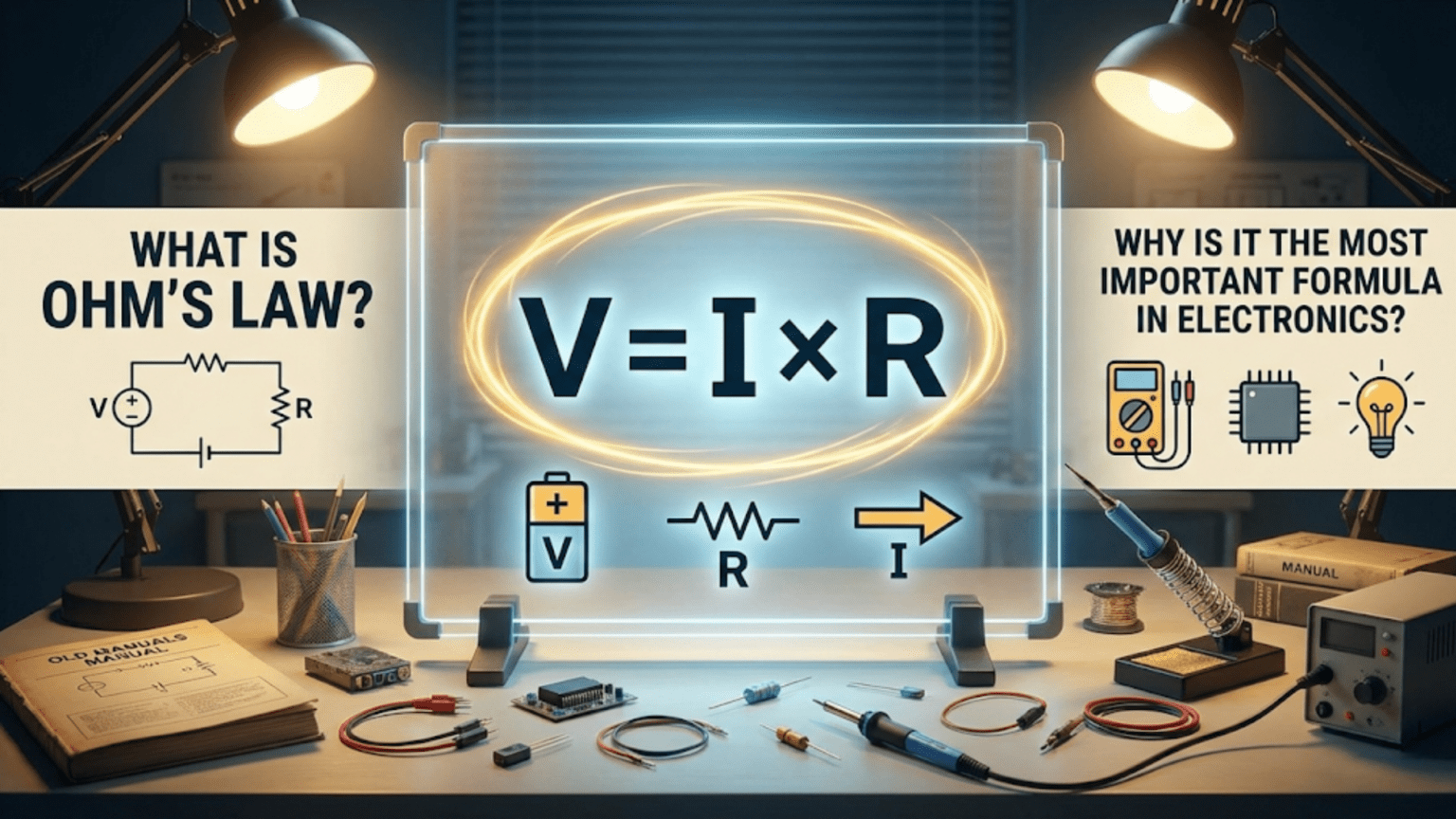
Ohm’s Law is the fundamental relationship stating that voltage equals current multiplied by resistance (V = I × R), describing how these three electrical quantities interact in any circuit. This simple yet powerful formula is considered the most important equation in electronics because it allows engineers and hobbyists to predict, design, and troubleshoot virtually every electrical circuit, from simple LED connections to complex computer processors.
Introduction: The Foundation of All Electronics
If electronics were a building, Ohm’s Law would be its foundation. This remarkably simple mathematical relationship has stood as the cornerstone of electrical engineering since German physicist Georg Simon Ohm discovered it in 1827. Nearly two centuries later, it remains the first formula every electronics student learns and the last one every experienced engineer forgets.
The beauty of Ohm’s Law lies not just in its simplicity—a relationship between just three variables—but in its universal applicability. Whether you’re designing a smartphone charging circuit, troubleshooting a malfunctioning amplifier, or calculating how much current will flow through a simple LED, Ohm’s Law provides the answer. It’s the Swiss Army knife of electronics formulas, relevant in virtually every situation an electronics enthusiast or professional engineer encounters.
But Ohm’s Law is more than just a formula to memorize. It represents a fundamental truth about how electricity behaves in conductors. Understanding this relationship doesn’t just help you solve math problems—it develops your intuition about how circuits work, enabling you to predict circuit behavior before you even pick up a multimeter or solder a single component.
In this comprehensive guide, we’ll explore every aspect of Ohm’s Law: what it is, why it matters, how to apply it in real-world situations, and why this single equation deserves its reputation as the most important formula in all of electronics. Whether you’re just beginning your electronics journey or looking to deepen your understanding of this fundamental principle, this article will provide the knowledge you need to master this essential concept.
What Exactly is Ohm’s Law?
The Basic Formula
At its core, Ohm’s Law states a simple relationship between three fundamental electrical quantities:
V = I × R
Where:
- V represents voltage (measured in volts)
- I represents current (measured in amperes or amps)
- R represents resistance (measured in ohms)
This equation tells us that the voltage across a conductor is directly proportional to the current flowing through it, with the constant of proportionality being the resistance. In simpler terms, voltage equals current multiplied by resistance.
Understanding Each Component
Before we dive deeper into the law itself, let’s ensure we have a solid grasp of what each variable represents:
Voltage (V) is the electrical potential difference between two points—the “pressure” that pushes electrons through a circuit. Think of it as the height difference in a water system that creates pressure to move water through pipes. Without voltage, there’s no force to move electrons, and therefore no current flow.
Current (I) is the rate at which electric charge flows past a point in a circuit, measured as the number of electrons passing by per second. Using the water analogy, current is like the flow rate of water through a pipe—how much water passes through per second. The symbol “I” comes from “intensity” of current, though many beginners find this confusing at first.
Resistance (R) is the opposition to current flow in a material or component. It’s the electrical equivalent of friction in a pipe—something that resists the flow and converts some electrical energy into heat. Different materials have vastly different resistances: copper wire has very low resistance (which is why it’s used for wiring), while rubber has very high resistance (which is why it’s used for insulation).
The Three Forms of Ohm’s Law
While we typically see Ohm’s Law written as V = I × R, this single relationship can be algebraically rearranged into three equally valid forms:
- V = I × R (to find voltage when you know current and resistance)
- I = V ÷ R (to find current when you know voltage and resistance)
- R = V ÷ I (to find resistance when you know voltage and current)
Each form solves for a different variable, but they’re all expressing the same fundamental relationship. Many beginners find it helpful to use the “Ohm’s Law triangle” memory aid: draw a triangle with V at the top and I and R at the bottom. Cover the variable you want to find, and the triangle shows you the formula (V on top means I × R; I on left means V ÷ R; R on right means V ÷ I).
What Ohm’s Law Actually Tells Us
Beyond the mathematics, Ohm’s Law reveals some important truths about electrical behavior:
Direct Proportionality Between Voltage and Current: If you increase the voltage across a resistor while keeping resistance constant, the current increases proportionally. Double the voltage, and you double the current. This linear relationship makes circuit behavior predictable and calculable.
Inverse Proportionality Between Resistance and Current: If you increase resistance while keeping voltage constant, current decreases inversely. Double the resistance, and you halve the current. This is why resistors are so useful for controlling current flow in circuits.
The Resistance Determines the Relationship: The resistance value acts as the conversion factor between voltage and current for any given component or circuit. It tells you how much current will flow for every volt of pressure applied.
These relationships aren’t arbitrary mathematical constructs—they describe the actual physical behavior of electricity in conductors, making Ohm’s Law a true natural law rather than just a convenient approximation.
The Historical Context: Georg Ohm’s Discovery
The Pioneering Work of Georg Simon Ohm
Georg Simon Ohm (1789-1854) was a German physicist and mathematician who discovered the relationship that now bears his name. Born in Erlangen, Bavaria, Ohm came from a modest background—his father was a locksmith who nonetheless valued education and taught his son mathematics, physics, and philosophy.
In 1827, while working as a mathematics teacher at the Jesuit Gymnasium of Cologne, Ohm published his findings in a book titled “Die galvanische Kette, mathematisch bearbeitet” (The Galvanic Circuit Investigated Mathematically). This work described his experimental investigations into the relationship between voltage, current, and resistance in electrical circuits.
The Experimental Setup
Ohm’s experiments were remarkably sophisticated for his time. He used:
Thermoelectric piles as voltage sources (batteries were still primitive and inconsistent in Ohm’s day). These devices produced voltage from temperature differences, providing more stable voltage than the voltaic piles commonly available.
Wire of various materials and lengths to introduce different resistances into his circuits. Ohm systematically varied wire length, thickness, and material to understand how these factors affected current flow.
A torsion balance galvanometer to measure current—a sensitive device that detected current flow by measuring the twisting force on a suspended magnet. This was cutting-edge measurement technology for 1827.
Through meticulous experimentation and mathematical analysis, Ohm discovered that the current flowing through a conductor was directly proportional to the voltage applied across it and inversely proportional to its resistance. This might seem obvious to us now, but in Ohm’s time, the behavior of electricity was still mysterious and poorly understood.
Initial Rejection and Later Recognition
Surprisingly, Ohm’s work was initially met with skepticism and even ridicule from the scientific establishment. His quantitative approach to electricity was considered too theoretical, and many physicists of the time preferred qualitative descriptions over mathematical formulations.
The hostile reception so discouraged Ohm that he resigned from his teaching position. For years, his groundbreaking work remained largely unrecognized, particularly in Germany. However, his ideas gradually gained acceptance, especially in Britain, where scientists like Peter Barlow and Charles Wheatstone recognized their importance.
By the 1850s, Ohm’s Law had become widely accepted as a fundamental principle of electrical science. In 1841, the Royal Society of London awarded Ohm the Copley Medal, its highest honor, and in 1872, the ohm was adopted as the official unit of electrical resistance in his honor.
Ohm’s story reminds us that even the most fundamental scientific truths aren’t always immediately recognized. His persistence in the face of criticism and his rigorous experimental methodology set the foundation for modern electrical engineering.
Why Ohm’s Law is Considered the Most Important Formula in Electronics
Universal Applicability Across All Circuits
The title of “most important formula in electronics” isn’t given lightly. Ohm’s Law earns this distinction through its remarkable universality. Unlike many formulas that apply only in specific situations, Ohm’s Law works in virtually every electrical context:
From DC to AC circuits: While Ohm’s Law was originally developed for direct current (DC) circuits, it applies equally to alternating current (AC) circuits when dealing with purely resistive loads. For circuits with capacitors and inductors, the concept extends to impedance, but the fundamental V = I × R relationship remains at the core.
From nano-scale to power grid scale: Whether you’re analyzing the behavior of electrons in a transistor just nanometers across or calculating current flow in power transmission lines spanning hundreds of miles, Ohm’s Law applies. The same formula that helps you design a simple LED circuit also helps engineers design power distribution systems for entire cities.
Across all resistive materials: Ohm’s Law works for copper wires, carbon resistors, semiconductor materials, and even less common conductors like salt water or the human body. Any material that obeys ohmic behavior (most conductors do) follows this relationship.
In combination circuits: Even in complex circuits with multiple components, resistors, and voltage sources, Ohm’s Law applies to each individual component and section. You can break down any circuit into smaller parts and apply Ohm’s Law to each one.
The Foundation for All Circuit Analysis
Ohm’s Law isn’t just important on its own—it’s the foundation upon which virtually all other circuit analysis techniques are built:
Kirchhoff’s Laws depend on it: Gustav Kirchhoff’s Current Law (KCL) and Voltage Law (KVL) are the other fundamental circuit laws, and both are applied in conjunction with Ohm’s Law to analyze complex circuits. Without Ohm’s Law, you couldn’t determine the actual current and voltage values that Kirchhoff’s Laws help you relate.
Power calculations require it: The formulas for electrical power (P = V × I, P = I² × R, P = V² ÷ R) are all derived from or intimately connected to Ohm’s Law. Understanding power consumption and dissipation—critical for everything from battery life to heat management—requires Ohm’s Law.
Thevenin and Norton theorems use it: These powerful circuit simplification techniques, which allow engineers to reduce complex circuits to simpler equivalent forms, are built on Ohm’s Law principles. Without understanding V = I × R, these theorems would be meaningless.
Superposition and mesh/nodal analysis rely on it: Advanced circuit analysis techniques all use Ohm’s Law as a fundamental tool. Every equation you write when analyzing a circuit with these methods includes Ohm’s Law relationships.
Practical Problem-Solving Power
Beyond theoretical importance, Ohm’s Law is invaluable for practical, everyday electronics work:
Component selection: Need to choose the right resistor for an LED? Ohm’s Law tells you exactly what value you need. Want to know what voltage regulator to use? Ohm’s Law helps you calculate the current requirements.
Troubleshooting circuits: When a circuit doesn’t work as expected, Ohm’s Law helps you diagnose the problem. If you measure an unexpected voltage somewhere, Ohm’s Law helps you trace the issue back to a failed component or incorrect connection.
Design verification: Before building a circuit, you can use Ohm’s Law to verify that your design will work as intended. Will that resistor get too hot? Will the power supply provide enough current? Ohm’s Law answers these questions.
Safety calculations: Understanding current flow is essential for electrical safety. Ohm’s Law helps you calculate how much current could flow through your body in various scenarios, informing safe design practices.
Educational Value
From a learning perspective, Ohm’s Law is the perfect starting point for electronics education:
Simple yet profound: The formula is simple enough for a middle school student to understand, yet profound enough to remain relevant throughout an engineer’s entire career. This makes it an ideal entry point to the field.
Builds intuition: Working with Ohm’s Law develops your intuition about how circuits behave. After enough practice, you start to automatically sense when a circuit design might have current that’s too high or voltage that’s too low.
Demonstrates scientific method: Ohm’s Law is easily verifiable through simple experiments. Students can measure voltage, current, and resistance in real circuits and see the relationship confirmed, building confidence in both the formula and the scientific method.
Connects math to physical reality: Ohm’s Law provides a clear, tangible example of how mathematical relationships describe physical phenomena, helping students understand why mathematics is so important in engineering and science.
The Gateway to Advanced Concepts
Mastering Ohm’s Law opens doors to understanding more complex electrical concepts:
Impedance in AC circuits: The AC equivalent of resistance (impedance) follows similar relationships, with the formula V = I × Z being a direct extension of Ohm’s Law.
Semiconductor behavior: Understanding how voltage and current relate in resistive materials provides the foundation for understanding the more complex relationships in semiconductor devices like diodes and transistors.
Field theory and Maxwell’s equations: At the most advanced level, Ohm’s Law connects to Maxwell’s equations and the fundamental physics of electromagnetic fields.
Understanding the Mathematical Relationships in Depth
The Linear Relationship: Graphing Ohm’s Law
One of the most illuminating ways to understand Ohm’s Law is through graphical representation. When we plot current (I) on one axis and voltage (V) on the other for a constant resistance, we get a straight line passing through the origin.
The slope equals resistance: In a V-I graph (voltage on the vertical axis, current on the horizontal), the slope of the line equals the resistance. A steep slope indicates high resistance (small current change for large voltage change), while a gentle slope indicates low resistance (large current change for small voltage change).
What the line tells us: Any point on the line represents a valid operating point for that resistor. If you know the voltage (find it on the vertical axis), you can trace across to the line and then down to find the corresponding current. This visual representation helps build intuition about the V-I relationship.
Comparing different resistances: If you plot multiple resistances on the same graph, you get a family of lines, all passing through the origin but with different slopes. This visualization makes it easy to see how different resistances affect the current for a given voltage.
Non-ohmic behavior: For components that don’t follow Ohm’s Law perfectly (diodes, thermistors, lamps), the V-I curve isn’t a straight line. Comparing these curves to the linear ohmic case helps us understand what makes these components special.
Proportionality and Ratios
The mathematical concept of proportionality is central to Ohm’s Law:
Direct proportionality of V and I: When we say voltage is directly proportional to current (for constant R), we mean that if you double the voltage, current doubles; triple the voltage, current triples. Mathematically, V ∝ I (the ∝ symbol means “is proportional to”).
Inverse proportionality of I and R: Current is inversely proportional to resistance (for constant V), meaning if you double the resistance, current halves; triple the resistance, current becomes one-third. Mathematically, I ∝ 1/R.
The proportionality constant: Resistance is the proportionality constant that relates voltage and current. It’s the number that converts between these two quantities.
Ratio thinking: Many electronics problems become easier when you think in ratios. If you increase resistance by 50%, current decreases to 2/3 of its original value (because 1 ÷ 1.5 = 0.667). This ratio-based thinking is faster than recalculating everything from scratch.
Units and Dimensional Analysis
Understanding units is crucial for correctly applying Ohm’s Law:
The volt (V): One volt is defined as one joule per coulomb (1 V = 1 J/C), representing the energy per unit charge. In practical terms, it’s the potential difference that will drive one ampere through one ohm of resistance.
The ampere (A): One ampere is defined as one coulomb per second (1 A = 1 C/s), representing the flow rate of electric charge. An ampere represents about 6.24 × 10^18 electrons flowing past a point every second.
The ohm (Ω): One ohm is defined as one volt per ampere (1 Ω = 1 V/A), representing the resistance that allows one ampere to flow when one volt is applied.
Dimensional consistency: When you perform Ohm’s Law calculations, checking that your units work out correctly can catch errors. If you’re calculating current, you should end up with amperes; if the units don’t match, you’ve made a mistake somewhere.
Unit prefixes: Electronics work involves a huge range of values, from nanoamperes to kiloamperes. Understanding metric prefixes (milli-, micro-, kilo-, mega-) and converting between them correctly is essential. For example, 1 milliampere (1 mA) equals 0.001 amperes, and 1 kilohm (1 kΩ) equals 1000 ohms.
Mathematical Manipulations and Rearrangements
Being comfortable with algebraic manipulation of Ohm’s Law is essential:
Solving for each variable: You should be able to quickly rearrange the formula to solve for any unknown. If you know I and R and need to find V, multiply them. If you know V and I and need R, divide V by I. If you know V and R and need I, divide V by R.
Substitution in complex formulas: Often you’ll need to substitute Ohm’s Law into other formulas. For example, the power formula P = V × I can be rewritten as P = (I × R) × I = I² × R by substituting V = I × R.
Working with reciprocals: In parallel resistance calculations, you’ll work with the reciprocal of resistance (1/R), called conductance. Being comfortable with reciprocals makes these calculations smoother.
Maintaining equation balance: When manipulating equations, remember that whatever you do to one side, you must do to the other. This basic algebraic principle ensures your rearrangements are valid.
Practical Applications: Ohm’s Law in Action
Example 1: Calculating Current for an LED Circuit
Let’s work through a practical example that every electronics beginner encounters: determining the current-limiting resistor for an LED.
The scenario: You want to power a red LED from a 9V battery. The LED has a forward voltage drop of 2V and a maximum safe current of 20 mA (0.02 A).
Step 1: Determine the voltage across the resistor The resistor needs to drop the excess voltage. Since the battery provides 9V and the LED drops 2V, the resistor must drop: V_resistor = 9V – 2V = 7V
Step 2: Apply Ohm’s Law to find resistance Using R = V ÷ I: R = 7V ÷ 0.02A = 350Ω
Step 3: Select a standard resistor value Since 350Ω isn’t a standard resistor value, you’d choose the next larger standard value, which is 390Ω. This will result in slightly less than 20 mA, which is safer for the LED.
Step 4: Verify the actual current With a 390Ω resistor: I = V ÷ R = 7V ÷ 390Ω ≈ 0.018A = 18 mA
This calculation demonstrates how Ohm’s Law helps you design safe, functional circuits. Without it, you’d be guessing at resistor values and potentially damaging components.
Example 2: Troubleshooting a Power Supply Circuit
Imagine you’ve built a circuit that should draw 500 mA from a 5V power supply, but it’s not working. You measure the voltage at the load and find only 3V instead of 5V.
Step 1: Calculate the expected resistance If the circuit should draw 500 mA (0.5 A) at 5V: R = V ÷ I = 5V ÷ 0.5A = 10Ω
Step 2: Calculate the actual resistance With 500 mA flowing but only 3V at the load: R = V ÷ I = 3V ÷ 0.5A = 6Ω
Step 3: Find the missing voltage The missing 2V (5V – 3V = 2V) must be dropping somewhere between the power supply and the load.
Step 4: Calculate the resistance of the problem With 0.5A flowing and 2V dropping: R_problem = 2V ÷ 0.5A = 4Ω
The diagnosis: There’s an extra 4Ω of resistance somewhere in your circuit—probably a poor connection, undersized wire, or a component that’s partially failed. This Ohm’s Law analysis has pointed you directly to the problem.
Example 3: Determining Wire Size for a Project
You’re building a robot that needs to carry 5A of current through wires from the battery to the motors, and you want no more than 0.1V drop across each wire to maximize efficiency.
Step 1: Calculate maximum acceptable wire resistance Using R = V ÷ I: R = 0.1V ÷ 5A = 0.02Ω
Step 2: Consider wire length If your wires need to be 2 feet (about 0.6 meters) long, you need wire with a resistance of no more than 0.02Ω per 0.6m, or about 0.033Ω per meter.
Step 3: Select appropriate wire gauge Consulting a wire resistance table, you’d find that 18 AWG wire has a resistance of about 0.021Ω per meter, which meets your requirement. Thicker wire (lower gauge number) would be even better but might be unnecessarily expensive or bulky.
This example shows how Ohm’s Law informs practical design decisions beyond just component selection.
Example 4: Calculating Heating in Resistors
You’re using a 100Ω resistor with 12V across it. How much power does it dissipate, and is a standard 1/4 watt resistor sufficient?
Step 1: Calculate the current Using I = V ÷ R: I = 12V ÷ 100Ω = 0.12A = 120 mA
Step 2: Calculate power dissipation Using P = V × I: P = 12V × 0.12A = 1.44W
Or, using P = V² ÷ R: P = (12V)² ÷ 100Ω = 144 ÷ 100 = 1.44W
The verdict: A 1/4 watt resistor is definitely not sufficient—it would quickly overheat and fail. You need at least a 2-watt resistor, preferably a 3-watt or higher for safety margin.
This calculation demonstrates how Ohm’s Law connects to power calculations, helping you design circuits that won’t fail from overheating.
Example 5: Measuring Unknown Resistance
You have a mystery resistor and want to know its value, but the color bands are unreadable. You apply 5V across it and measure 15 mA of current. What’s the resistance?
Using R = V ÷ I: R = 5V ÷ 0.015A = 333.33Ω
The resistor is approximately 330Ω (a standard value), and the color bands probably read orange-orange-brown (if they were legible).
This example shows how Ohm’s Law can be used with measurement tools to characterize components.
Common Mistakes and Misconceptions About Ohm’s Law
Mistake 1: Confusing Voltage Across with Voltage Sources
The misconception: Beginners often confuse the total voltage from a power supply with the voltage across an individual component.
The reality: In any circuit with multiple components, the voltage from the power supply is divided among the components. The “V” in Ohm’s Law refers to the voltage across the specific component you’re analyzing, not the total supply voltage.
Example: If you have a 9V battery connected to two resistors in series (100Ω and 200Ω), the voltage across each resistor is NOT 9V. The current through the series circuit is I = 9V ÷ 300Ω = 30 mA, and the voltages are V₁ = 30 mA × 100Ω = 3V and V₂ = 30 mA × 200Ω = 6V.
How to avoid it: Always identify clearly which component or circuit section you’re analyzing, and be precise about which voltage you’re using in your calculations.
Mistake 2: Applying Ohm’s Law to Non-Ohmic Components
The misconception: Ohm’s Law works for everything in a circuit.
The reality: Ohm’s Law applies only to ohmic materials and components—those where resistance remains constant regardless of voltage or current. Many important components are non-ohmic.
Non-ohmic components include:
- Diodes: Resistance varies dramatically with voltage; they conduct heavily in one direction and barely at all in the other
- LEDs: Similar to diodes, with a threshold voltage below which they don’t conduct
- Transistors: Their operation is fundamentally non-linear
- Thermistors: Resistance changes with temperature
- Lamp filaments: Resistance increases as they heat up
- Batteries and voltage sources: They maintain voltage rather than presenting constant resistance
How to avoid it: Learn which components are ohmic (resistors, most wire, many passive components) and which aren’t. For non-ohmic components, use their specific characteristic equations or datasheets.
Mistake 3: Unit Conversion Errors
The misconception: You can use whatever units are convenient without conversion.
The reality: Ohm’s Law requires consistent units—volts, amperes, and ohms. Using milliamperes or kilohms without converting leads to wrong answers.
Example error: Calculating R = 5V ÷ 20 mA and getting 0.25Ω (wrong!) instead of converting 20 mA to 0.02A first and getting 250Ω (correct).
How to avoid it: Always convert to base units (V, A, Ω) before calculating, or carefully track your unit prefixes through the calculation. Many calculators and design tools help with this, but understanding the math yourself prevents errors.
Mistake 4: Forgetting About Power Dissipation
The misconception: As long as the voltage and current values work mathematically, the circuit will function.
The reality: Resistors (and all components) have power ratings. Exceeding these ratings causes overheating and component failure, even if the Ohm’s Law calculations are perfect.
Example: Calculating that a 10Ω resistor needs to carry 1A is fine mathematically, but that resistor will dissipate P = I² × R = 1² × 10 = 10 watts. A standard quarter-watt resistor would instantly fail.
How to avoid it: Always calculate power dissipation (using P = V × I, P = I² × R, or P = V² ÷ R) and verify that your components are rated for it. Use safety margins—don’t run components at their maximum rating.
Mistake 5: Ignoring Internal Resistance
The misconception: Power supplies and batteries are perfect voltage sources with no resistance.
The reality: All real voltage sources have internal resistance that affects circuit behavior, especially under high current loads.
Example: A 9V battery with 2Ω internal resistance powering a 10Ω load will deliver V_load = 9V × (10Ω ÷ 12Ω) = 7.5V to the load, not the full 9V. The internal resistance drops V_internal = 9V × (2Ω ÷ 12Ω) = 1.5V.
How to avoid it: For precise calculations, model your power source as an ideal voltage source in series with its internal resistance. This is particularly important for batteries and power supplies under heavy load.
Mistake 6: Misunderstanding What Resistance Really Is
The misconception: Resistance is just a property of resistors.
The reality: Everything has resistance—wires, switches, connectors, circuit board traces, even multimeter probes. Usually this resistance is negligible, but in precision circuits or high-current applications, it matters.
Example: A 20-foot run of 22 AWG wire has about 0.32Ω of resistance. At 5A, this drops V = 5A × 0.32Ω = 1.6V, which could be significant in a low-voltage circuit.
How to avoid it: Consider the resistance of everything in your circuit, especially for high-current, low-voltage, or precision applications. Wire resistance, contact resistance, and connector resistance can all affect performance.
Mistake 7: Circular Logic in Calculations
The misconception: You can find all three values (V, I, R) from Ohm’s Law alone.
The reality: Ohm’s Law relates three quantities, but you need to know at least two of them to find the third. You can’t pull all three values from thin air.
Example error: “I need to find the current through this resistor” without knowing either the voltage across it or the resistance value. Ohm’s Law can’t help until you know at least two of the three variables.
How to avoid it: Always ensure you have at least two known values before trying to apply Ohm’s Law. In complex circuits, you might need to use Kirchhoff’s Laws or other techniques to determine some values first.
Ohm’s Law in Different Types of Circuits
DC Circuits: The Fundamental Application
Direct current (DC) circuits are where Ohm’s Law shines in its purest form. In DC circuits, voltage and current are constant over time, making calculations straightforward.
Simple series circuits: In a series circuit, the same current flows through all components. Ohm’s Law helps you find the voltage drop across each component (V = I × R for each resistor) and verify that these voltage drops sum to the source voltage.
Practical example: A battery-powered flashlight has a 6V battery and three resistors in series: R₁ = 10Ω, R₂ = 15Ω, R₃ = 5Ω. Total resistance is 30Ω, so current is I = 6V ÷ 30Ω = 0.2A. The voltage drops are V₁ = 2V, V₂ = 3V, V₃ = 1V, which sum to 6V, confirming our calculation.
Simple parallel circuits: In a parallel circuit, voltage across all components is the same. Ohm’s Law helps you find the current through each branch (I = V ÷ R for each resistor) and verify that these currents sum to the total current from the source.
Practical example: A 12V power supply connected to three parallel resistors: R₁ = 100Ω, R₂ = 200Ω, R₃ = 300Ω. Each resistor has 12V across it, so currents are I₁ = 120 mA, I₂ = 60 mA, I₃ = 40 mA, totaling 220 mA from the power supply.
Mixed series-parallel circuits: Real circuits often combine series and parallel sections. Ohm’s Law applies to each component individually, but you must carefully analyze the circuit structure to know whether components share the same current (series) or voltage (parallel).
AC Circuits: Resistance and Beyond
In alternating current (AC) circuits, voltage and current vary sinusoidally with time. For purely resistive loads, Ohm’s Law still applies directly, but the values represent RMS (root mean square) values rather than instantaneous values.
Purely resistive AC loads: A heater, incandescent lamp, or resistor behaves the same whether powered by DC or AC. If you measure 120V RMS across a 100Ω resistor, the current is I = 120V ÷ 100Ω = 1.2A RMS, just as it would be for DC.
The role of frequency: For pure resistors, frequency doesn’t matter—the resistance is the same at 60 Hz (US power grid frequency) as it is for DC. However, for capacitors and inductors, frequency dramatically affects their opposition to current flow.
Impedance: The AC equivalent: In circuits containing capacitors or inductors, we use impedance (Z) instead of resistance (R), and the relationship becomes V = I × Z. Impedance has both magnitude and phase, making AC analysis more complex, but the fundamental Ohm’s Law relationship remains.
Power factor considerations: In AC circuits with reactive components (capacitors and inductors), current and voltage can be out of phase, affecting power calculations. This is beyond basic Ohm’s Law but builds upon its principles.
Complex Circuits: Iterative Application
For circuits with multiple voltage sources, many components, or complex interconnections, Ohm’s Law is applied repeatedly in combination with other circuit laws.
Node voltage method: In this analysis technique, you assign a voltage to each node (connection point) in the circuit, then apply Ohm’s Law to express the current through each component in terms of node voltages. This creates a system of equations you can solve.
Mesh current method: Here, you assume loop currents flowing around each circuit loop, then apply Ohm’s Law to express voltage drops in terms of these loop currents. Again, this creates solvable equations.
Superposition theorem: When analyzing circuits with multiple sources, you can use superposition: analyze the circuit with each source active individually (others turned off), applying Ohm’s Law to each case, then sum the results.
The key insight: No matter how complex the circuit, Ohm’s Law applies to each component individually. The art of circuit analysis is breaking complex circuits into manageable pieces where Ohm’s Law can be applied.
Digital Circuits: Hidden Applications
Even in digital circuits (where we mostly think about logic levels rather than continuous voltages), Ohm’s Law is constantly at work behind the scenes.
Pull-up and pull-down resistors: These resistors ensure proper logic levels on digital inputs. Calculating their values requires Ohm’s Law to balance input current requirements against switching speed.
Current limiting for digital outputs: Digital outputs often drive LEDs or other loads. Ohm’s Law determines the resistors needed to limit current to safe levels while maintaining adequate voltage for the load.
Transmission line analysis: At high speeds, even circuit board traces behave as transmission lines with characteristic impedance. Understanding signal integrity requires Ohm’s Law applications.
Power distribution: Digital circuits draw current from power supplies. Ohm’s Law governs voltage drops in power distribution networks, affecting whether ICs receive adequate voltage for proper operation.
Advanced Concepts: Beyond Basic Ohm’s Law
Temperature Effects on Resistance
Real resistors don’t have constant resistance—their resistance changes with temperature, which can create interesting and sometimes problematic effects.
Temperature coefficient of resistance: Most materials have a temperature coefficient (α) that describes how resistance changes with temperature. For most metals, resistance increases with temperature (positive temperature coefficient). For semiconductors and carbon, resistance typically decreases with temperature (negative temperature coefficient).
The modified Ohm’s Law: When accounting for temperature, resistance becomes R(T) = R₀ × [1 + α × (T – T₀)], where R₀ is the resistance at reference temperature T₀, and T is the current temperature.
Practical implications: In precision circuits, temperature changes can cause resistance changes that affect circuit behavior. A copper wire’s resistance increases about 0.4% per degree Celsius, which might seem small but matters in precision measurements.
Self-heating in resistors: When current flows through a resistor, power dissipation causes heating, which changes the resistance. This creates a feedback effect where increased resistance might reduce current, which reduces heating, creating a new equilibrium.
Thermistors: Using temperature effects: Some components (thermistors) are specifically designed to have large temperature coefficients, making them useful as temperature sensors. Understanding their behavior requires considering how resistance varies with temperature.
Non-Linear Resistance
Not all materials follow Ohm’s Law—some have resistance that varies with voltage or current.
Voltage-dependent resistors (varistors): These components have resistance that decreases dramatically when voltage exceeds a threshold. They’re used for surge protection but don’t follow Ohm’s Law.
Current-dependent effects: In some materials, high current density can cause heating or other effects that change resistance during operation.
Diode characteristics: While diodes are clearly non-ohmic, understanding their I-V curves helps illustrate what Ohm’s Law predicts (linear relationship) versus what actually happens (exponential relationship).
Practical design considerations: When working with non-linear components, you can sometimes approximate their behavior as ohmic over small voltage or current ranges, allowing Ohm’s Law to provide rough estimates.
Ohm’s Law at Microscopic Scales
At the atomic level, Ohm’s Law connects to fundamental physics in fascinating ways.
Drift velocity: Current flow results from electrons drifting through a conductor under the influence of an electric field. Ohm’s Law emerges from the relationship between this drift velocity and the applied voltage.
Mean free path: Electrons collide with atoms in the conductor, and these collisions create resistance. Materials where electrons travel farther between collisions (longer mean free path) have lower resistance.
Band theory and conductivity: In quantum mechanical terms, a material’s resistance relates to its electronic band structure—how easily electrons can move between energy levels.
The quantum Hall effect: At extremely low temperatures and high magnetic fields, resistance becomes quantized, and the classical Ohm’s Law breaks down in favor of quantum mechanical descriptions.
Ohm’s Law and Maxwell’s Equations
At the most fundamental level, Ohm’s Law connects to electromagnetic field theory through Maxwell’s equations.
The local form of Ohm’s Law: Instead of V = I × R, the fundamental relationship is J = σ × E, where J is current density (current per unit area), σ is conductivity (the reciprocal of resistivity), and E is electric field strength.
The connection to circuit theory: The familiar V = I × R form emerges when you integrate this field relationship over a conductor’s length and cross-sectional area.
Why this matters: Understanding this connection shows that Ohm’s Law isn’t arbitrary—it’s a consequence of how electric fields cause charges to move through matter.
Frequency-Dependent Effects
At high frequencies, even simple resistors don’t behave exactly as Ohm’s Law predicts for DC.
Skin effect: At high frequencies, current concentrates near the surface of conductors rather than distributing uniformly. This effectively reduces the conductor’s cross-sectional area, increasing resistance.
Parasitic capacitance and inductance: Every resistor has tiny amounts of capacitance and inductance associated with it. At high frequencies, these become significant and make the component behave differently than a pure resistance.
Practical implications: In radio frequency (RF) circuits, component selection must consider these frequency-dependent effects, not just the DC resistance value.
Ohm’s Law Problem-Solving Strategies
The Systematic Approach
When faced with an Ohm’s Law problem, following a systematic process prevents errors and builds confidence:
Step 1: Read the problem carefully and identify what you know Write down all given values. Be explicit about units, converting everything to volts, amperes, and ohms if necessary.
Step 2: Identify what you need to find What is the problem asking for? Voltage, current, or resistance? Sometimes you’ll need to find multiple values or perform multi-step calculations.
Step 3: Draw a circuit diagram if one isn’t provided Visual representation helps you understand the circuit structure and relationships between components.
Step 4: Choose the appropriate form of Ohm’s Law Select V = I × R, I = V ÷ R, or R = V ÷ I based on what you know and what you need to find.
Step 5: Perform the calculation Do the math carefully, tracking units throughout.
Step 6: Check your answer for reasonableness Does the answer make physical sense? Is a 1000A current flowing through a resistor realistic, or did you forget to convert milliamperes? Would a 0.001Ω resistance make sense for a standard resistor, or did you make a unit error?
Step 7: Verify with alternative methods if possible Can you check your answer by calculating a different value and seeing if it’s consistent?
Building Intuition Through Estimation
Before reaching for a calculator, develop the habit of estimating answers:
Order of magnitude thinking: If you’re dividing 12V by 1000Ω, you know the answer will be in the milliampere range (12 ÷ 1000 = 0.012A = 12 mA) before calculating precisely.
Round number approximation: For quick checks, round values to convenient numbers. If you have 4.7V and 220Ω, approximate as 5V and 200Ω to estimate current as 5 ÷ 200 = 0.025A = 25 mA (actual: ~21 mA).
Proportional thinking: If you double the voltage, current doubles. If you halve the resistance, current doubles. Use these relationships for quick mental checks.
Sanity bounds: Know what’s reasonable. Currents in electronics typically range from microamperes to tens of amperes. Resistances typically range from milliohms to megohms. Voltages typically range from millivolts to hundreds of volts. If your answer falls far outside these ranges, double-check your calculation.
Multi-Step Problems
Complex problems often require applying Ohm’s Law multiple times:
Strategy: Work step by step Find one unknown value, then use it to find the next, building toward the final answer. Don’t try to jump directly to the answer in complex circuits.
Strategy: Use intermediate variables Assign variable names to intermediate results. Instead of one massive equation, break the problem into smaller pieces with labels like I_total, V_series, R_parallel, etc.
Strategy: Check at each step Verify each intermediate result before using it in the next calculation. Errors compound in multi-step problems, so catching them early saves time.
Example approach: In a series-parallel circuit, first find the equivalent resistance of the parallel section, then find the total current from the source, then find the voltage across the parallel section, then find the current through each parallel branch. Each step uses Ohm’s Law with results from previous steps.
Common Problem Patterns
Recognizing common problem types helps you solve them more efficiently:
Pattern 1: The current-limiting resistor Given a voltage source and a component with known voltage and current requirements, find the resistor needed to drop the excess voltage. Seen in LED circuits, voltage regulation, sensor biasing.
Pattern 2: The voltage divider Given a source voltage and a ratio of resistances, find the output voltage. Seen in sensor interfaces, biasing networks, reference voltage creation.
Pattern 3: The power rating check Given a resistor value and circuit conditions, verify that power dissipation is within the component’s rating. Critical for reliable circuit design.
Pattern 4: The equivalent resistance Given a network of resistors, find the single resistance value that would draw the same current from the source. Foundation for analyzing complex circuits.
Pattern 5: The unknown component Given measurements of two quantities (typically voltage and current), determine the unknown third quantity (typically resistance). Common in troubleshooting and reverse engineering.
Practical Measurement and Verification
Using a Multimeter to Verify Ohm’s Law
Theory is important, but seeing Ohm’s Law work in practice builds true understanding. A simple experiment can verify the relationship:
Equipment needed:
- A multimeter capable of measuring voltage, current, and resistance
- A resistor (100Ω to 1000Ω works well for this experiment)
- A variable power supply or battery
- Connecting wires and a breadboard
Procedure:
Step 1: Measure the resistance Set your multimeter to resistance mode and measure the resistor. If it reads 470Ω (for example), this is your R value.
Step 2: Build the circuit Connect the resistor to your power supply (start with 5V) through your multimeter set to current mode. The multimeter must be in series with the resistor to measure current.
Step 3: Measure current With 5V applied, record the current reading. For a 470Ω resistor, you should measure approximately I = 5V ÷ 470Ω ≈ 10.6 mA.
Step 4: Calculate expected current Using Ohm’s Law with your measured resistance and applied voltage, calculate what the current should be.
Step 5: Compare Your measured current should match your calculated current within a few percent (accounting for measurement error and resistor tolerance).
Step 6: Vary the voltage Try different voltages (2V, 3V, 7V, etc.) and verify that current changes proportionally. If you double the voltage, does current double? This demonstrates the direct proportionality.
Step 7: Graph your results Plot voltage on one axis and current on the other. The resulting line should be straight, passing through the origin, with slope equal to the resistance.
Measurement Challenges and Errors
Real-world measurements introduce complications that pure theory doesn’t have:
Meter burden: When measuring current, the multimeter adds a small amount of resistance to the circuit (the shunt resistor it uses to sense current). This can slightly affect the current you’re trying to measure, especially in high-resistance circuits.
Contact resistance: The connection points between components, wires, and test probes all have small resistances that add to the total. In precision measurements, these matter.
Resistor tolerance: Resistors are manufactured to tolerances (typically 5%, 1%, or 0.1%). A 100Ω resistor with 5% tolerance could actually be anywhere from 95Ω to 105Ω, affecting your measurements.
Temperature effects: As current flows and the resistor heats up, its resistance changes slightly. For power resistors or high-current measurements, this can be significant.
Measurement precision: Multimeters have limited precision (typically 3 to 4 digits). Small measurement errors in V or I create errors in calculated R, and vice versa.
Best practices:
- Use good quality test leads with solid connections
- Allow circuits to stabilize thermally before critical measurements
- Account for component tolerances in your expectations
- Use the most precise measurement ranges on your multimeter
- Repeat measurements to catch errors
- Calculate expected values beforehand so you’ll notice if measurements are way off
Practical Tolerance and Real-World Components
Component specifications include tolerances that affect how closely real circuits match Ohm’s Law calculations:
Resistor tolerances:
- 5% tolerance (gold band): Most common for general-purpose resistors
- 1% tolerance (brown band): Precision resistors for critical applications
- 0.1% tolerance: High-precision resistors for metrology and sensitive circuits
Voltage source tolerances: Batteries and power supplies have their own tolerances and regulation specifications. A “9V” battery might be anywhere from 8.5V to 9.6V when fresh.
Current measurement tolerances: Your multimeter itself has accuracy specifications, typically ±(0.5% of reading + 2 digits).
Cumulative effects: When you combine multiple component tolerances, errors can add up. In precision work, you might need to select specific components or trim circuits to achieve exact values.
Design philosophy: Good circuit design accounts for component tolerances. Circuits should work correctly even when every component is at the edge of its tolerance range. This is called “worst-case analysis.”
Teaching Ohm’s Law: Effective Learning Strategies
Hands-On Experimentation
The most effective way to learn Ohm’s Law is through direct experimentation:
Start with simple circuits: Build a circuit with a battery, resistor, and LED. Measure the current and voltage, and verify that they match Ohm’s Law predictions. Seeing theory confirmed by measurement is powerful.
Vary one parameter at a time: Keep resistance constant and change voltage, observing how current changes. Then keep voltage constant and change resistance (by swapping resistors), observing current changes. This isolates each relationship.
Make predictions first: Before measuring, calculate what you expect to see. This transforms measurement from passive observation to active hypothesis testing.
Intentionally create problems: Build a circuit with too much current (maybe an LED without a resistor), calculate what would happen, then try it briefly (very briefly!) to see the LED get too bright or burn out. Seeing what happens when you violate design rules drives lessons home (though don’t make this too expensive!).
Use simulation software: Tools like Falstad Circuit Simulator, LTspice, or CircuitLab let you build virtual circuits and immediately see voltage and current values everywhere. This allows unlimited experimentation without component costs or damage risks.
Visual and Conceptual Aids
Different learners benefit from different representations of the same concept:
The water analogy: Voltage is water pressure, current is flow rate, and resistance is pipe size or obstacles in the pipe. While not perfect (no analogy is), this helps beginners develop intuition.
The Ohm’s Law triangle: A memory aid showing V at the top, I and R at the bottom. Cover the variable you want to find, and the triangle shows the formula.
Graphical representations: Plotting V versus I for different resistances visualizes the relationship more clearly than formulas alone.
Interactive calculators: Online Ohm’s Law calculators where you adjust sliders and immediately see other values update help build intuition about how the variables relate.
Physical demonstrations: Adjustable power supplies with built-in voltmeters and ammeters let you see values change in real-time as you adjust voltage.
Common Learning Roadblocks
Many students struggle with specific aspects of Ohm’s Law:
Unit confusion: The most common issue is mixing units—using milliamperes where amperes are needed, or kilohms where ohms are required. Emphasizing unit conversion and dimensional analysis helps.
Identifying which voltage to use: In complex circuits, students often use the wrong voltage value. Practice identifying which component or section you’re analyzing and which voltage applies to it.
Distinguishing V, I, and R: Some students mix up which symbol means what. Using full words (voltage, current, resistance) initially, before transitioning to symbols, can help.
Understanding proportionality: The concept that doubling one quantity doubles or halves another isn’t intuitive for everyone. Concrete examples with numbers help more than abstract explanations.
Knowing when to apply Ohm’s Law: Students sometimes try to apply it where it doesn’t belong (across voltage sources, across non-ohmic components). Teaching component classifications helps.
Progressive Complexity
Learning Ohm’s Law should follow a logical progression:
Stage 1: Single resistor, one voltage source Master the basics with the simplest possible circuits. Calculate current given voltage and resistance. Calculate voltage given current and resistance. Calculate resistance given voltage and current.
Stage 2: Series circuits Learn that the same current flows through all series components. Practice finding voltage drops across multiple resistors.
Stage 3: Parallel circuits Understand that parallel components have the same voltage. Practice finding current through each branch.
Stage 4: Series-parallel combination circuits Learn to analyze mixed circuits by breaking them into series and parallel sections.
Stage 5: Power calculations Connect Ohm’s Law to power formulas. Learn to verify component power ratings.
Stage 6: Real-world applications Apply knowledge to practical projects: LED circuits, voltage dividers, sensor interfaces.
Stage 7: Advanced topics Explore temperature effects, AC circuits, non-linear behavior, and other complexities.
Ohm’s Law in Professional Practice
Circuit Design Applications
Professional engineers use Ohm’s Law constantly throughout the design process:
Initial concept design: When sketching out a new circuit, engineers use Ohm’s Law to quickly estimate component values and verify that the design is feasible.
Component selection: Ohm’s Law determines what resistors, wires, switches, and other components are needed. It ensures components can handle expected currents and voltages.
Power budget analysis: Understanding how much current each section draws helps engineers determine power supply requirements and battery life.
Thermal analysis: Ohm’s Law helps calculate power dissipation in components, which drives thermal design decisions about heat sinks, airflow, and PCB layout.
Safety analysis: Calculating potential current paths helps engineers ensure circuits won’t create shock hazards or fire risks.
Cost optimization: Ohm’s Law helps identify where cheaper components can be used without affecting performance and where precision components are truly necessary.
Troubleshooting and Debugging
When circuits don’t work as expected, Ohm’s Law is the first diagnostic tool:
Identifying shorts: If measured current is much higher than expected, Ohm’s Law calculations point to lower-than-expected resistance somewhere—often indicating a short circuit.
Finding open circuits: If current is zero or much lower than expected, resistance is higher than it should be—pointing to an open connection, failed component, or wiring error.
Voltage drop analysis: Unexpected voltage drops between two points indicate resistance that shouldn’t be there—poor connections, undersized wires, or component failures.
Component verification: Measuring voltage and current and calculating resistance can verify whether a component has failed or changed value.
Signal integrity issues: In fast digital circuits, Ohm’s Law helps analyze whether impedance mismatches or resistive losses are causing signal problems.
Manufacturing and Quality Control
Ohm’s Law plays important roles in manufacturing electronics:
Test fixture design: Automated test equipment uses Ohm’s Law to verify that assembled circuit boards have correct resistances, indicating proper assembly.
In-circuit testing: Test systems apply known voltages and measure currents to verify component values and detect assembly errors like wrong components or poor solder joints.
Calibration procedures: Precision equipment is calibrated using known resistances and Ohm’s Law calculations to verify accuracy.
Burn-in testing: During product burn-in (running products at elevated temperature to detect early failures), Ohm’s Law helps monitor whether components are drifting out of specification.
Standards and Specifications
Industry standards reference Ohm’s Law extensively:
Safety standards: Electrical safety standards (like UL, IEC, CE) specify maximum currents, minimum resistances, and other parameters that prevent hazards. Compliance requires Ohm’s Law calculations.
Performance specifications: Component datasheets specify operating conditions in terms of voltage, current, and resistance ranges—all related through Ohm’s Law.
Interface standards: Communication and power delivery standards (USB, HDMI, Ethernet, etc.) specify impedances, voltage levels, and current capabilities, requiring Ohm’s Law for implementation.
Test methods: Standardized test procedures for measuring component characteristics often involve applying voltage and measuring current (or vice versa) to determine resistance or other parameters.
Comparison Table: Ohm’s Law vs. Related Electrical Laws
| Aspect | Ohm’s Law (V = I × R) | Kirchhoff’s Current Law (KCL) | Kirchhoff’s Voltage Law (KVL) | Joule’s Law (P = I² × R) |
|---|---|---|---|---|
| What it describes | Relationship between voltage, current, and resistance in a conductor | Conservation of charge at a circuit node | Conservation of energy around a circuit loop | Power dissipation in a resistor |
| Mathematical form | V = I × R (also I = V/R, R = V/I) | Σ I_in = Σ I_out at any node | Σ V = 0 around any closed loop | P = I² × R = V² / R = V × I |
| Primary application | Finding unknown V, I, or R when two are known | Analyzing current distribution in circuits | Analyzing voltage distribution in circuits | Calculating heat dissipation and power consumption |
| When to use | Single component or simple circuit section | Anywhere currents split or combine | Anywhere you need voltage drops around a loop | Whenever power/heat is a concern |
| Limitations | Only applies to ohmic (linear) materials | Universal for all circuits | Universal for all circuits | Assumes power converts to heat (true for resistors) |
| Typical units | Volts, amperes, ohms | Amperes | Volts | Watts |
| Difficulty level | Beginner | Intermediate | Intermediate | Beginner |
| Relationship to Ohm’s Law | Fundamental law | Independent principle, often used with Ohm’s Law | Independent principle, often used with Ohm’s Law | Derived from Ohm’s Law |
| Example use case | “What current flows through a 100Ω resistor with 5V across it?” | “If 2A enters a node and 1A goes one way, how much goes the other way?” | “If I have 12V supply and drop 5V and 4V, what’s the third drop?” | “How much heat does a 10Ω resistor dissipate with 2A flowing?” |
Conclusion: Mastering the Foundation of Electronics
Ohm’s Law, with its deceptively simple equation V = I × R, stands as the single most important formula in electronics. Its importance stems not from mathematical complexity—any middle school student can understand the basic algebra—but from its universal applicability and profound implications for understanding electrical behavior.
Why Mastery Matters
True mastery of Ohm’s Law goes far beyond memorizing a formula. It means developing an intuitive sense for how voltage, current, and resistance interact. When you’ve mastered Ohm’s Law, you can:
Predict circuit behavior before building or measuring. You know that increasing resistance will reduce current, that doubling voltage will double current, and that power dissipation increases with the square of current.
Design circuits confidently by calculating component values that will produce desired behavior. You can select resistors, size wires, choose power supplies, and ensure safety—all through Ohm’s Law applications.
Troubleshoot effectively by using measurements and calculations to pinpoint problems. Unexpected voltages or currents become clues that guide you to faulty components or design errors.
Communicate clearly with other engineers and technicians using the common language of voltage, current, and resistance relationships.
The Path to Mastery
Achieving Ohm’s Law mastery requires:
Understanding the concepts deeply, not just memorizing formulas. Know what voltage, current, and resistance actually represent physically.
Practice with diverse problems ranging from simple to complex, from theoretical to practical, from DC to AC circuits.
Hands-on experimentation to see theory confirmed in reality. Build circuits, measure values, verify calculations.
Teaching others because explaining concepts to someone else reveals gaps in your own understanding and solidifies knowledge.
Applying knowledge in projects where Ohm’s Law becomes a natural tool you reach for without conscious thought.
Beyond the Basics
As you advance in electronics, you’ll encounter situations where basic Ohm’s Law seems insufficient—AC circuits with reactive components, high-frequency effects, quantum phenomena, and more. But rather than replacing Ohm’s Law, these advanced topics build upon it. The fundamental relationship between voltage, current, and resistance remains valid; it just gets expressed in more sophisticated forms using impedance, complex numbers, and field theory.
Even experienced engineers with decades of experience and knowledge of the most advanced circuit theory still use Ohm’s Law daily. It’s not a beginner topic to be outgrown—it’s a fundamental tool that grows with you throughout your entire career.
Your Journey Forward
If you’re just beginning your electronics education, invest the time to truly master Ohm’s Law. Work through many problems. Build circuits and verify your calculations. Develop that intuitive feel for how the variables relate. This foundation will serve you throughout your entire electronics journey.
If you’re already experienced, periodically revisit the fundamentals. Are there aspects of Ohm’s Law you take for granted but don’t fully understand? Can you explain why it works at the atomic level? Do you understand its connection to Maxwell’s equations? There’s always deeper insight to be gained.
The beauty of Ohm’s Law is that it rewards both beginners and experts. It’s simple enough to learn in an afternoon, yet profound enough to study for a lifetime. It’s the most important formula in electronics not because it’s the most complex or comprehensive, but because it’s the most fundamental, the most universal, and the most useful.
Master Ohm’s Law, and you’ve taken the first crucial step toward mastering electronics itself. The journey of a thousand circuits begins with this single formula: V = I × R.
Final Thoughts
Georg Simon Ohm discovered his famous law nearly two centuries ago using primitive equipment and facing skepticism from his peers. Today, that same simple relationship enables everything from smartphones to spacecraft, from LED light bulbs to particle accelerators. The voltage-current-resistance relationship he uncovered isn’t just a useful approximation or convenient engineering shortcut—it’s a fundamental truth about how electricity behaves in our universe.
Every time you flip a light switch, charge your phone, or use any electronic device, you’re relying on systems designed using Ohm’s Law. Understanding this formula doesn’t just help you build circuits—it connects you to the fundamental physics of electricity and the rich history of electrical science.
Whether you’re a student just beginning to explore electronics, a hobbyist building your first circuit, or a professional engineer designing cutting-edge technology, Ohm’s Law remains your constant companion. Embrace it, master it, and let it guide you through the fascinating world of electronics.
V = I × R. Three symbols. Infinite applications. The most important formula in electronics.