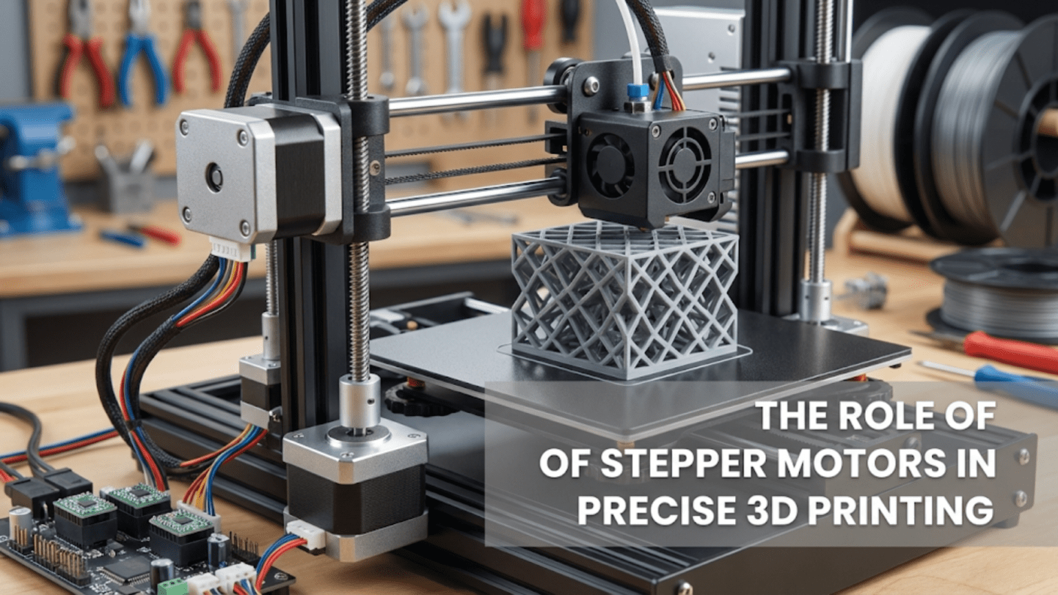
Stepper motors are precision electric motors that rotate in discrete angular steps rather than continuous rotation, making them ideal for 3D printing’s positional accuracy requirements. Unlike standard DC motors, steppers move a fixed angular distance (typically 1.8 degrees per step) with each electrical pulse they receive, allowing printers to position the print head, bed, and extruder to exact locations without requiring position feedback sensors, while maintaining their position firmly when powered even under external forces.
Introduction
Every successful 3D print depends on extraordinarily precise positioning. When your printer builds an object layer by layer, the nozzle must move to exact coordinates—sometimes accurate to hundredths of a millimeter—depositing material in precisely the right locations at precisely the right times. A deviation of just 0.1mm can mean the difference between a dimensionally accurate part and a failed print.
This remarkable precision comes from stepper motors—the workhorses that power nearly every consumer 3D printer. These specialized motors possess unique characteristics that make them nearly perfect for additive manufacturing. They provide precise position control without feedback sensors, hold position firmly when stationary, respond instantly to movement commands, and cost relatively little despite their sophisticated capabilities.
Yet many 3D printer users take stepper motors for granted, never understanding why they work so well or what distinguishes them from other motor types. When motor problems arise—skipped steps, strange noises, reduced accuracy—users often don’t know whether the issue involves the motor itself, the driver electronics, mechanical resistance, or configuration settings.
In this comprehensive guide, we’ll explore exactly how stepper motors work, why they’re ideal for 3D printing, what the specifications mean, how driver electronics control them, and what can go wrong. You’ll understand the engineering principles that enable precise positioning, learn to identify and solve motor-related problems, and gain the knowledge needed to optimize your printer’s motion system performance.
What Makes Stepper Motors Special
Before understanding why steppers excel at 3D printing, we need to understand what they are and how they differ from other motor types:
Discrete Step Movement
The fundamental characteristic that defines stepper motors is their discrete stepping action. Rather than spinning continuously like a DC motor, steppers rotate in precise angular increments called steps. Each electrical pulse sent to the motor causes exactly one step of rotation.
Most 3D printer stepper motors use a step angle of 1.8 degrees. Since a full circle contains 360 degrees, these motors take exactly 200 steps to complete one full rotation (360 ÷ 1.8 = 200). This relationship is so consistent that you can count steps to know the exact rotational position—no encoder or position sensor required.
This discrete movement provides inherent positioning capability. If you command 400 steps, the motor rotates exactly two full turns. Command 100 steps and it rotates precisely one-half turn. The microcontroller tracks position simply by counting pulses sent to the motor.
The stepping action results from the motor’s internal construction. Electromagnets inside the motor housing (called stator coils) energize in precise sequences, pulling a toothed rotor to specific positions. Change which coils are energized, and the rotor moves to a new position. Each sequence change constitutes one step.
Position Holding Without Feedback
When a stepper motor sits idle with power applied, it actively holds its position. The energized electromagnets create a magnetic field that locks the rotor at its current step position. Try to rotate the motor shaft by hand and you’ll feel strong resistance—the holding torque that resists movement.
This holding characteristic provides critical benefits for 3D printing. When the printer stops moving to change direction or pause briefly, the motors maintain position precisely. There’s no drift or settling. When movement resumes, the printer starts from exactly where it stopped.
Compare this to DC motors, which coast when power is removed and require active braking or position sensors to hold a specific position. The stepper’s passive holding through magnetic forces eliminates this complexity.
The holding torque specification indicates how much rotational force the motor can resist before slipping from its commanded position. Higher holding torque motors resist larger disturbances, important for applications involving significant resistance or external forces.
No Position Sensor Required
Perhaps the most significant advantage for cost-sensitive applications like consumer 3D printers: steppers provide accurate position control without encoders, resolvers, or other position sensors. The controller simply counts the step pulses it sends, knowing the motor has moved that many steps.
This open-loop control works because of the stepper’s synchronous operation—each step pulse causes exactly one step of movement, assuming the motor doesn’t lose steps (more on that later). The predictable relationship between pulses and position eliminates the need for expensive feedback sensors.
Position sensors for DC servo motors can cost as much as the entire stepper motor. Multiplying this cost across four or five axes in a printer would significantly increase the total price. Steppers deliver precision positioning at a fraction of the cost.
Instant Response to Direction Changes
Steppers respond immediately to changes in step pulse direction. To reverse rotation, you simply reverse the direction signal sent to the driver. There’s no momentum to overcome or delayed response. The next step pulse moves the motor in the new direction instantly.
This responsiveness enables the rapid direction changes common in 3D printing. The print head constantly changes direction—moving right, then up, then left, then down, thousands of times while printing a single layer. Each direction change happens instantly without motor lag.
How Stepper Motors Work: Internal Operation
Understanding the internal operation helps you appreciate why steppers behave as they do and troubleshoot problems effectively:
Electromagnetic Stepping Mechanism
Inside a stepper motor, two main components interact: the stator (stationary electromagnets) and the rotor (rotating permanent magnet or toothed iron core).
The stator consists of multiple electromagnetic coils wrapped around iron poles. When current flows through a coil, it becomes magnetized, creating north and south magnetic poles. Most 3D printer steppers use four coils arranged in two pairs (phases). Each phase contains two coils connected so they always produce opposite magnetic polarity.
The rotor contains many teeth—typically 50 teeth around its circumference. These teeth are made from magnetic material that responds to the stator’s magnetic field. The rotor might also incorporate permanent magnets in hybrid designs.
When you energize one phase of the stator coils, magnetic attraction pulls the rotor teeth into alignment with the energized stator poles. The rotor snaps to this stable position and holds there firmly. To create rotation, you energize the phases in sequence, creating a rotating magnetic field that pulls the rotor along step by step.
The number of rotor teeth and stator poles determines the step angle. With 50 rotor teeth and the standard 4-pole, 2-phase configuration, you get 200 steps per revolution (1.8 degrees per step). This geometry is nearly universal in 3D printer motors.
Four-Phase Stepping Sequence
The driver electronics energize the motor’s two phases in specific sequences to create rotation. Several stepping modes exist:
Full step mode energizes one or two phases at a time. In single-phase excitation, only one phase is energized, and the rotor aligns with those poles. In dual-phase excitation, both phases energize simultaneously, and the rotor positions halfway between them. Alternating between these creates rotation.
A full step sequence might look like:
- Phase A+ only (rotor at position 0°)
- Phase A+ and B+ together (rotor at position 1.8°)
- Phase B+ only (rotor at position 3.6°)
- Phase B+ and A- together (rotor at position 5.4°)
- Phase A- only (rotor at position 7.2°) And so on…
Half-step mode combines single-phase and dual-phase excitation, creating intermediate positions. This doubles the resolution to 400 steps per revolution (0.9 degrees per step). The motor moves more smoothly but with slightly less torque at the half-step positions.
Microstepping divides each full step into even smaller increments by varying the current in each phase precisely. Instead of coils being simply “on” or “off,” the driver applies varying current levels that create intermediate magnetic field strengths. By carefully controlling the current waveform in both phases, the driver can position the rotor at many points between full step positions.
Common microstepping settings include 1/4, 1/8, 1/16, and 1/32 step modes. At 1/16 microstepping, a motor with 200 full steps per revolution moves in 3,200 microsteps per revolution—an angular resolution of just 0.1125 degrees per microstep.
Current Control and Torque
The torque a stepper motor produces depends on the current flowing through its coils. More current creates stronger magnetic fields, producing more torque. However, you can’t simply increase current indefinitely—excessive current overheats the motor, potentially damaging the coil insulation or demagnetizing rotor magnets.
Each motor has a rated current specification indicating the maximum continuous current it can handle without overheating. Typical 3D printer NEMA 17 motors are rated for 1.5 to 2.0 amps per phase.
The driver electronics regulate current to the specified level, controlling torque output. Setting the driver’s current limit involves adjusting a potentiometer or configuring firmware values to match the motor’s rating. Too little current and the motor lacks torque to overcome resistance. Too much current causes overheating, excessive noise, and potential damage.
Modern stepper drivers employ sophisticated current control methods. Chopper-style drivers rapidly switch the voltage on and off, adjusting the duty cycle to maintain the desired average current. This allows using higher voltage power supplies (which enable faster stepping rates) while precisely controlling the actual current through the motor coils.
NEMA Standards and Motor Sizing
When selecting or discussing stepper motors, you’ll encounter NEMA size designations. Understanding what these mean helps you choose appropriate motors:
NEMA Size Nomenclature
NEMA (National Electrical Manufacturers Association) standards define stepper motor mounting dimensions. The NEMA number indicates the mounting face size in tenths of inches.
NEMA 17 motors have a 1.7 inch (approximately 42mm) square mounting face. This represents by far the most common size in 3D printers. The standardized mounting pattern means motors from different manufacturers are mechanically interchangeable.
NEMA 23 motors feature a 2.3 inch (approximately 57mm) mounting face. These larger motors produce significantly more torque and find use in larger industrial printers or CNC machines.
NEMA 14 and NEMA 11 are smaller standards occasionally used in compact printer designs or for low-torque applications like extruders in some configurations.
The NEMA designation specifies only the mounting dimensions—bolt pattern, shaft diameter, and mounting face size. It doesn’t specify the motor’s length, torque output, current rating, or other performance characteristics. You can have wildly different motors all classified as NEMA 17.
Length and Torque Relationship
For a given NEMA size, motor length correlates strongly with torque output. Longer motors contain more copper in their coils and more magnetic material in their cores, producing higher torque.
Common NEMA 17 lengths include:
- 20-25mm “pancake” motors: Very short, low torque (typically 10-15 N·cm), used where weight matters more than force
- 34-40mm motors: Medium torque (25-40 N·cm), adequate for many applications
- 48mm motors: Standard high torque (40-48 N·cm), common in quality 3D printers
- 60mm motors: Extra-high torque (55-65 N·cm), used in demanding applications
The torque specification (measured in Newton-centimeters or ounce-inches) indicates how much rotational force the motor can produce. Higher torque allows overcoming greater resistance—important for moving heavy beds, pushing filament through restrictive hotends, or achieving high accelerations with heavier carriages.
Torque-Speed Curves
Stepper motor torque isn’t constant across all speeds. Motors produce maximum torque at low speeds (or when stationary), with torque decreasing as stepping rate increases. This relationship appears in torque-speed curves provided in motor specifications.
At very low speeds (below 100 steps per second), the motor operates near its holding torque specification. As speed increases, torque gradually drops. The rate of decrease depends on motor design and the voltage driving it. Higher voltage systems maintain torque better at high speeds.
This torque reduction at high speeds explains why printers sometimes skip steps during very fast movements but work fine at slower speeds. The combination of high speed and high resistance (from heavy moving parts or mechanical friction) can exceed the available torque, causing the motor to stall momentarily.
Understanding your motor’s torque curve helps you set realistic speed limits. If you want to print at aggressive speeds, you need motors with favorable torque curves and adequate voltage to maintain torque at high stepping rates.
Stepper Drivers: The Motor’s Brain
Stepper motors require sophisticated driver electronics to control their operation. The driver takes simple step and direction signals from the controller and translates them into the complex current waveforms needed to make the motor move:
Driver Functions
Current regulation: The driver maintains precise current levels in each motor phase despite varying resistance, inductance, and back-EMF effects. This ensures consistent torque output.
Microstepping generation: The driver creates the precisely controlled current waveforms needed for smooth microstepping. This requires accurate digital-to-analog conversion and current sensing.
Protection: Good drivers include overcurrent protection, overtemperature shutdown, and short-circuit detection to prevent damage to the driver or motor.
Chopper control: The driver rapidly switches voltage on and off to control current, allowing use of higher voltages for better high-speed torque while maintaining safe current levels.
Common Driver Types
Several driver chip families appear in 3D printers, each with different capabilities and characteristics:
A4988: An older but still common driver chip. Simple, inexpensive, reliable. Supports up to 1/16 microstepping and 2A per phase. However, it runs relatively loud and lacks advanced features. Many budget printers still use A4988 drivers.
DRV8825: A step up from the A4988, supporting 1/32 microstepping and 2.5A current. Somewhat quieter operation. Still relatively simple and affordable.
TMC2208: A modern driver featuring stealthChop technology for virtually silent operation at low and medium speeds. Supports 1/256 microstepping (though practical benefit beyond 1/16 is minimal). More expensive than older drivers but dramatically quieter.
TMC2209: An improved version of the 2208 adding stallGuard sensorless homing capability, better thermal performance, and spreadCycle mode for improved high-speed performance. Represents an excellent balance of features, performance, and cost for modern printers.
TMC2130/TMC5160: Higher-end drivers with advanced features like sensorless homing, load monitoring, and sophisticated diagnostics. More expensive, typically used in premium printers.
Driver Configuration
Drivers require proper configuration to work correctly:
Current setting: You must set the driver’s current limit to match your motor’s rating. This typically involves adjusting a small potentiometer on the driver (older designs) or setting values in firmware (newer integrated drivers).
The formula for setting current via potentiometer voltage measurement varies by driver type. For A4988 drivers, the reference voltage relates to current through the equation: I = Vref / 0.4. For TMC drivers, consult the specific datasheet or configurator tools.
Setting current too low causes weak torque and possible missed steps. Setting it too high overheats motors and wastes energy. Exact motor rating is ideal, though many users run slightly below rating (90-95%) to reduce heat and noise while maintaining adequate torque.
Microstepping selection: Some drivers use jumpers to select microstepping level. Others configure via firmware. Higher microstepping creates smoother motion and reduces noise but requires more processing power and may not improve actual positioning accuracy beyond a certain point.
Most printers operate well at 1/16 microstepping. Higher levels (1/32, 1/64, 1/256) typically don’t improve print quality meaningfully while increasing computational load on the controller.
StealthChop vs. SpreadCycle: TMC drivers support multiple operating modes. StealthChop provides silent operation ideal for printing but may lose torque at very high speeds. SpreadCycle offers maximum torque at all speeds but runs louder. Some printers use hybrid approaches—stealthChop during printing, spreadCycle during fast travel moves or homing.
Stepper Motors in 3D Printer Axes
3D printers typically use four or five stepper motors, each serving specific roles:
X and Y Axis Motors
These motors control the horizontal positioning of the print head or bed. In Cartesian printers, one motor moves the head left-right (X-axis) while another moves the bed forward-backward (Y-axis), or in some designs, the head moves in both axes.
Requirements: X and Y motors need adequate torque to accelerate the moving mass quickly. Higher acceleration capability allows faster printing without sacrificing quality. The motors must also overcome belt friction and bearing resistance.
For small to medium printers with lightweight carriages, standard 40-48mm NEMA 17 motors suffice. Larger printers or those with heavier direct drive extruders may benefit from higher torque motors.
The X-axis in many designs moves less mass than the Y-axis (which often moves the entire bed), allowing a smaller motor if weight reduction matters. However, using identical motors on both axes simplifies parts inventory and provides consistent performance.
Z-Axis Motors
The Z-axis motor(s) lift the print head or bed vertically. This axis moves more slowly than X and Y but often carries more weight and uses lead screws that require more torque to turn.
Requirements: High torque at low speeds matters more than high-speed capability. The motor must lift the weight of the bed or gantry against gravity while turning the lead screw against friction.
Many printers use two Z-axis motors connected to separate lead screws, one on each side of the gantry. This provides more stable vertical movement and allows independent adjustment for gantry tramming. Some designs couple both motors to a single driver output (mechanically linked), while others use independent drivers for each motor.
The Z-axis stepping resolution directly affects layer height precision. With a typical 8mm lead screw and a 200-step motor, each full step moves 0.04mm vertically (8mm ÷ 200). With 1/16 microstepping, this becomes 0.0025mm per microstep—far finer than any practical layer height.
Extruder Motor
The extruder motor pushes filament into the hotend at precisely controlled rates. This motor faces unique challenges compared to axis motors.
Requirements: The extruder motor must overcome significant resistance from pushing plastic through the restrictive hotend path and tiny nozzle orifice. It needs high torque at relatively low speeds. Unlike axis motors that move in both directions freely, the extruder predominantly pushes in one direction against substantial back-pressure.
Geared extruders use mechanical reduction between the motor and filament drive gear, multiplying torque. This allows using smaller, lighter motors (sometimes pancake steppers) while achieving adequate filament pushing force.
Direct drive extruder configurations mount the motor on the moving carriage, making motor weight critical. Lighter motors reduce moving mass, enabling faster printing. Bowden configurations mount the motor stationary on the frame, eliminating weight concerns but introducing other challenges like increased retraction distances.
Steps Per Millimeter: Translating Steps to Movement
For the motor’s discrete steps to produce accurate physical movement, the firmware must know the relationship between motor steps and actual linear motion:
Calculation Fundamentals
The steps-per-millimeter value tells the firmware how many motor steps move the axis exactly one millimeter. This depends on several mechanical factors:
For belt-driven axes (X and Y):
- Motor steps per revolution (200 for 1.8° motors)
- Microstepping setting (typically 16x = 3200 microsteps/rev)
- Pulley teeth count (commonly 16 or 20 teeth)
- Belt pitch (2mm for standard GT2 belts)
The formula: Steps/mm = (motor steps/rev × microstepping) / (pulley teeth × belt pitch)
Example: With 200 steps/rev, 16x microstepping, 20-tooth pulley, and 2mm belt pitch: Steps/mm = (200 × 16) / (20 × 2) = 3200 / 40 = 80 steps/mm
For lead screw axes (Z):
- Motor steps per revolution (200 for 1.8° motors)
- Microstepping setting (typically 16x = 3200 microsteps/rev)
- Lead screw lead (distance traveled per revolution, commonly 8mm or 2mm)
The formula: Steps/mm = (motor steps/rev × microstepping) / lead screw lead
Example: With 200 steps/rev, 16x microstepping, and 8mm lead screw: Steps/mm = (200 × 16) / 8 = 3200 / 8 = 400 steps/mm
For extruders: The calculation involves gear ratios and effective diameter of the drive gear, making it more complex. Most users calibrate empirically by measuring actual filament movement.
Calibration Importance
Even with theoretical calculations, real-world systems benefit from empirical calibration. Manufacturing tolerances in pulleys, belts, and lead screws can create small variations from theoretical values.
To calibrate:
- Command a specific movement distance (e.g., 100mm)
- Measure actual movement with calipers
- Calculate correction factor: new value = (commanded/actual) × old steps/mm value
- Update firmware with corrected value
- Verify with another test movement
Proper calibration ensures dimensional accuracy in prints. Errors in steps/mm values directly translate to dimensional errors in finished parts.
Common Stepper Motor Problems
Understanding potential issues helps you diagnose and resolve problems quickly:
Skipped Steps
Symptoms: Layers shift partway through prints, creating offset sections. Dimensional accuracy suffers. In severe cases, motors make grinding or clicking sounds.
Causes:
- Motor current too low—increase driver current setting
- Moving too fast—reduce acceleration or maximum speed
- Mechanical binding—check for bent rods, tight bearings, debris in rails
- Driver overheating—improve cooling or reduce current slightly
- Worn mechanical components—replace belts, pulleys, or lead screw nuts
When a motor can’t produce enough torque to overcome resistance at its current stepping rate, it stalls briefly, missing steps. Each missed step accumulates as position error since the controller can’t detect the skip in open-loop control.
Excessive Noise
Symptoms: Motors produce loud buzzing, whining, or mechanical noise during movement.
Causes:
- Older driver types (A4988, DRV8825) inherently run louder than TMC drivers
- Current set too high—reduces excess current slightly
- Mechanical resonance at certain speeds—adjust acceleration, enable s-curve acceleration, or add dampers
- Loose motor mounting—tighten mounting screws
- Microstepping too low—increase from 1/8 to 1/16
Motor noise often relates to the driver type and current control method. Upgrading to TMC2208 or TMC2209 drivers dramatically reduces noise through their sophisticated current control algorithms.
Overheating
Symptoms: Motors too hot to touch (over 60-70°C), thermal shutdown, position loss due to temporary cutouts.
Causes:
- Current set too high—reduce to motor’s rated current
- Inadequate cooling—improve airflow around motors
- Motor stalling against resistance—reduce speed, fix mechanical binding
- Driver thermal issues—add heatsinks, improve driver cooling
- Sustained high-current operation—motors need cooling when running continuously at high current
Motors generate heat normally during operation—it’s okay for them to be warm (40-50°C). Excessive heat (too hot to touch for more than a few seconds) indicates problems. Modern drivers include thermal protection that reduces current or shuts down entirely if temperatures exceed safe limits.
Inconsistent Movement
Symptoms: Jerky motion, vibration, surface artifacts on prints, position inconsistency.
Causes:
- Incorrect microstepping—verify jumper settings or firmware configuration
- Driver configuration errors—check current, mode selection
- Electrical interference—route motor cables away from signal wires
- Loose connections—verify all wiring terminal tightness
- Intermittent driver faults—check for marginal solder joints, failing drivers
Smooth stepper operation requires proper driver configuration and clean electrical connections. Poor connections or configuration errors manifest as inconsistent motion quality.
Stepper Motor Specifications Comparison
| Specification | Low-End Motor | Standard Motor | High-Performance Motor |
|---|---|---|---|
| NEMA Size | 17 | 17 | 17 or 23 |
| Length | 34mm | 40-48mm | 48-60mm |
| Holding Torque | 28-32 N·cm | 40-45 N·cm | 50-65 N·cm |
| Rated Current | 1.2-1.5A | 1.5-1.8A | 1.8-2.5A |
| Step Angle | 1.8° (200 steps) | 1.8° (200 steps) | 1.8° or 0.9° (400 steps) |
| Weight | 250g | 300g | 350-450g |
| Typical Cost | $8-12 | $12-18 | $20-40 |
| Best For | Budget builds, light loads | General 3D printing | Large printers, heavy loads |
Advanced Stepper Concepts
Sensorless Homing (StallGuard)
Modern TMC drivers include stallGuard technology that detects when the motor stalls against an obstacle. This enables sensorless homing—the printer homes axes by running motors into end-of-travel mechanical stops, detecting the stall, and stopping automatically.
Benefits include eliminating endstop switches (reducing cost and complexity) and providing stall detection during printing that can pause prints if motors lose steps. However, it requires careful tuning and doesn’t work reliably at very low speeds or with extremely light loads.
Closed-Loop Steppers
Traditional steppers operate open-loop without position feedback. Closed-loop steppers add encoders that detect actual position, allowing the driver to detect and correct missed steps automatically.
These systems provide stepper simplicity with servo-like reliability, ensuring accuracy even under challenging conditions. However, they cost significantly more than standard steppers, limiting their use mostly to industrial or high-end printers.
0.9-Degree Motors
While most steppers use 1.8° step angles (200 steps/revolution), 0.9° motors double the resolution to 400 steps per revolution. This finer resolution can improve precision and reduce low-speed artifacts.
However, the practical benefit is often minimal since microstepping already provides adequate resolution. The 0.9° motors typically cost more and may produce slightly less torque at high speeds. Most users find standard 1.8° motors entirely adequate with proper microstepping.
S-Curve Acceleration
Standard motion control uses linear acceleration—velocity increases at a constant rate. This creates abrupt changes in acceleration (jerk) at the start and end of acceleration periods, potentially exciting mechanical resonances.
S-curve acceleration smoothly ramps acceleration up and down, creating an S-shaped velocity curve. This reduces mechanical stress, decreases vibration, and can improve print quality at the cost of slightly slower direction changes.
Modern firmware supports s-curve acceleration as an option, particularly beneficial for printers with less rigid frames or heavier moving assemblies.
Maintaining and Optimizing Stepper Performance
Keep your stepper motors performing optimally:
Proper current configuration: Set driver current correctly—not too high (wastes energy, creates heat) or too low (insufficient torque).
Mechanical maintenance: Lubricate lead screws, keep belts tensioned properly, ensure smooth bearing movement. Mechanical resistance forces motors to work harder.
Thermal management: Ensure adequate airflow around drivers and motors. Add heatsinks to drivers if needed. Keep motors away from heat sources like heated beds.
Electrical cleanliness: Route motor cables away from signal wires to prevent interference. Use shielded cables in electrically noisy environments.
Regular calibration: Periodically verify steps/mm accuracy, especially after mechanical changes or if dimensional accuracy declines.
Firmware optimization: Keep firmware updated, configure acceleration and jerk settings appropriately for your mechanics, enable advanced features like s-curve acceleration if beneficial.
Conclusion
Stepper motors represent the perfect marriage of precision, cost, and simplicity for 3D printing applications. Their ability to move in discrete, controllable steps without position sensors makes them ideal for the demanding positional requirements of additive manufacturing. The robust holding torque keeps everything exactly where it should be between movements. The instant response to direction changes enables the complex toolpaths that create intricate designs.
Understanding how these motors work—from the electromagnetic stepping mechanism through the sophisticated driver electronics to the mechanical translation of rotation into linear motion—transforms you from someone who simply uses 3D printers to someone who truly understands them. When problems arise, you can diagnose whether the issue involves motor selection, driver configuration, mechanical resistance, or firmware settings.
The stepper motor might seem like a simple component, just one of several motors in your printer. However, it’s the precision these motors deliver that makes dimensional accuracy possible. It’s their holding torque that prevents layer shifts. It’s their responsiveness that enables the rapid direction changes creating fine details. Every successful print depends on these motors performing their stepping dance perfectly, thousands of times per second, for hours on end.
Whether you’re running budget A4988 drivers with basic NEMA 17 motors or a sophisticated TMC2209-powered system with high-torque steppers, the fundamental principles remain the same. Proper configuration, adequate mechanical maintenance, and understanding the capabilities and limitations of your motors enable reliable, accurate printing. The stepper motor’s role in precise 3D printing isn’t glamorous, but it’s absolutely essential—the invisible foundation upon which all your creative works are built.