Introduction: The Most Important Component You’ll Ever Add
If you’re just starting in electronics, one of the first projects you’ll encounter is lighting up an LED. It seems simple enough: connect an LED to a battery and watch it glow. But here’s something that catches almost every beginner by surprise: connect an LED directly to a battery, and you’ll either get a brief flash followed by darkness as the LED dies, or nothing at all if you’re lucky enough to have a battery with enough internal resistance to limit the current.
This is one of the most important lessons in electronics: LEDs are not like incandescent light bulbs. You cannot simply connect them to a voltage source and expect them to work properly. LEDs require current control, and the simplest, most common way to provide that control is with a resistor in series with the LED.
Why is this resistor so critical? What happens inside an LED that makes it behave so differently from a light bulb? And how do you calculate the correct resistor value to protect your LED while getting the brightness you want? These are fundamental questions that every electronics hobbyist must answer, because getting this wrong doesn’t just mean a dim LED or a bright LED; it means a dead LED.
In this comprehensive guide, we’re going to thoroughly explore why LEDs need current-limiting resistors. We’ll start with the physics of how LEDs respond to voltage and current, then work through the mathematics of calculating resistor values step by step. We’ll cover multiple practical scenarios, discuss common mistakes and how to avoid them, and give you the deep understanding you need to confidently design LED circuits. By the end, calculating LED resistors will be second nature, and you’ll understand the principles well enough to handle even complex LED configurations.
Understanding LED Behavior: Why They’re Different
To understand why LEDs need resistors, we first need to understand how LEDs behave electrically, which is fundamentally different from the resistive loads like incandescent bulbs that most people intuitively understand.
The Incandescent Bulb: A Simple Resistor
When you connect an incandescent light bulb to a battery, it behaves essentially like a resistor. The filament has a certain resistance, and when you apply a voltage, current flows according to Ohm’s law. If you connect a 6-volt bulb rated for 0.5 amps to a 6-volt battery, it draws 0.5 amps and works perfectly. Connect it to a 9-volt battery, and it draws more current, glows brighter, and runs hotter, but it doesn’t immediately destroy itself.
The bulb’s resistance provides natural current limiting. As current increases, the filament heats up more, its resistance increases slightly, and this provides some negative feedback that prevents runaway current. The bulb is relatively forgiving of voltage variations.
The LED: An Exponential Current-Voltage Relationship
An LED is a diode, and diodes have a completely different current-voltage relationship than resistors. Below a certain voltage called the forward voltage or threshold voltage, almost no current flows through the LED. The LED is effectively an open circuit, blocking current like a wall blocks people.
Then, right around the forward voltage, something dramatic happens. The current starts to increase exponentially with voltage. A red LED might have a forward voltage around 2.0 volts. At 1.8 volts, essentially no current flows. At 2.0 volts, a small current flows, maybe a few milliamps. At 2.1 volts, the current might be tens of milliamps. At 2.2 volts, the current could be hundreds of milliamps or more.
This exponential relationship is described by the Shockley diode equation, and it means that once you exceed the forward voltage, small increases in voltage cause enormous increases in current. The LED does not behave like a resistor that limits its own current. Instead, it acts more like a voltage regulator that maintains approximately constant voltage across itself while allowing current to vary wildly.
What This Means Practically
Imagine you have a red LED with a 2.0V forward voltage and you connect it to a 5V battery with no resistor. The LED will try to maintain about 2.0V across itself. But that means there’s 3.0V of “extra” voltage that needs to be dropped somewhere in the circuit. With no resistor present, the only resistance is the tiny resistance of the wires and the internal resistance of the LED semiconductor material itself, which might total a fraction of an ohm.
Using Ohm’s law, 3.0V divided by, say, 0.1 ohm gives 30 amps. Of course, your battery can’t supply 30 amps, and the LED can’t survive 30 amps even for an instant, so what actually happens is that the LED draws whatever current the battery can provide. For a typical 9V battery with significant internal resistance, this might be several hundred milliamps. For a USB power supply or a good lithium battery with low internal resistance, it could be several amps.
Standard LEDs are designed to operate at currents between 5 and 20 milliamps. Anything above 30-50 milliamps will quickly overheat and destroy the LED. The semiconductor junction will literally melt or experience catastrophic damage. You might see a bright flash for a fraction of a second before the LED dies permanently.
The Need for External Current Limiting
Since the LED itself doesn’t limit current effectively, we need an external component to do that job. That component needs to drop the excess voltage (the supply voltage minus the LED’s forward voltage) while limiting current to a safe level for the LED.
The simplest and most common solution is a resistor in series with the LED. The resistor obeys Ohm’s law: the current through it is proportional to the voltage across it. By choosing the right resistance value, we can ensure that the current through the series circuit stays within safe limits for the LED.
This is why every LED circuit you’ll ever see (with rare exceptions we’ll discuss later) includes a current-limiting resistor. It’s not optional. It’s not just for optimal brightness. It’s absolutely essential for the LED’s survival.
The Physics Behind the Forward Voltage
To truly understand LED resistor calculations, it helps to understand where the forward voltage comes from and why it varies with LED color.
Energy Bands and Photon Emission
As we discussed in previous articles, LEDs emit light through a quantum mechanical process. When electrons and holes recombine at the PN junction, they release energy. In LEDs made from direct band gap semiconductors, this energy is released as photons of light.
The energy of each photon equals the band gap energy of the semiconductor material. The band gap is the energy difference between the valence band (where electrons are bound to atoms) and the conduction band (where electrons are free to move). When an electron drops from the conduction band to the valence band, it releases this exact amount of energy.
The forward voltage of an LED is directly related to this band gap energy. For an electron to get enough energy to cross from the valence band to the conduction band (which must happen before it can drop back down and emit a photon), it needs to gain energy from the electric field in the diode. This energy comes from the applied voltage.
The relationship is simple: the forward voltage in volts times the electron charge equals the photon energy in electron-volts, which approximately equals the band gap energy. This is why different color LEDs have different forward voltages.
Why Color Determines Forward Voltage
Different colors of light have different energies. Blue light has shorter wavelengths and higher energy photons than red light. To emit blue photons, an LED needs a larger band gap than for red photons. And a larger band gap means a higher forward voltage.
This is why red LEDs typically have forward voltages around 1.8 to 2.2 volts, while blue LEDs have forward voltages around 3.0 to 3.6 volts. Green and yellow LEDs fall in between, typically 2.0 to 2.5 volts. White LEDs, which are usually blue LEDs with a phosphor coating, have forward voltages similar to blue LEDs, around 3.0 to 3.4 volts.
When you’re calculating a current-limiting resistor, you must know the forward voltage of your specific LED. Using the wrong value in your calculation will give you the wrong resistor value, leading to either too much current (potentially destroying the LED) or too little current (making the LED very dim or not lighting at all).
The Forward Voltage Is Not Perfectly Constant
While we often treat the forward voltage as a fixed value for calculation purposes, it’s actually slightly dependent on current. As current through an LED increases, the forward voltage increases slightly, typically by a few tenths of a volt over the full operating range.
Additionally, the forward voltage depends on temperature. As an LED heats up, its forward voltage decreases slightly. This creates a potential problem: if the LED is driven by a constant voltage source, as it heats up and its forward voltage drops, more of the supply voltage appears across any series resistance, which increases current, which causes more heating, which decreases forward voltage further. This is why LEDs should ideally be driven with constant current sources rather than constant voltage sources with resistors.
However, for typical low-power LED applications with proper resistor values, this effect is small and manageable. The resistor provides enough stability to prevent thermal runaway. For high-power LEDs or critical applications, more sophisticated constant-current drivers are used instead of simple resistors.
The Basic Calculation: Step by Step
Now let’s work through the fundamental calculation for determining the current-limiting resistor value. We’ll start with the simplest case: a single LED powered by a DC source.
What Information You Need
Before you can calculate anything, you need three pieces of information. First, you need to know your supply voltage, the voltage of your power source whether it’s a battery, power supply, or other source. Second, you need to know the forward voltage of your LED, which should be specified in the LED’s datasheet or can be estimated based on color. Third, you need to know the desired current through the LED, which is typically between 5 and 20 milliamps for standard LEDs.
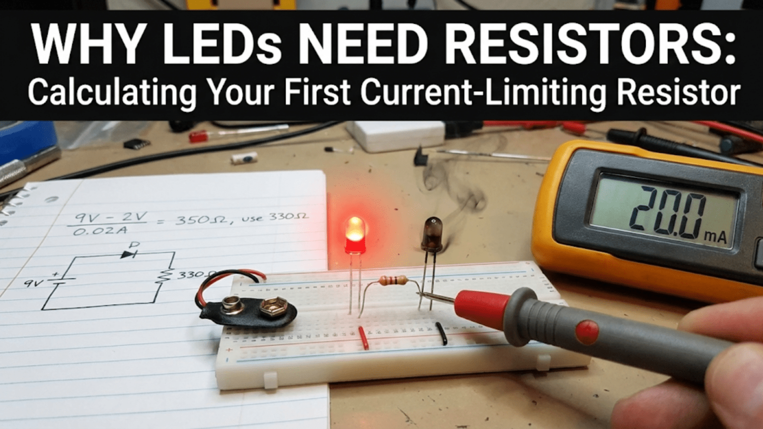
Let’s work with a concrete example. Suppose you have a 9-volt battery, a red LED with a forward voltage of 2.0 volts, and you want to run the LED at 15 milliamps, which will give good brightness without stressing the LED.
Step One: Calculate the Voltage to Drop
The resistor’s job is to drop the difference between the supply voltage and the LED’s forward voltage. This difference is the voltage that must appear across the resistor.
In our example, the supply voltage is 9.0 volts and the LED’s forward voltage is 2.0 volts. The voltage across the resistor must be 9.0V minus 2.0V, which equals 7.0 volts.
This makes intuitive sense. The 9 volts from the battery gets divided between two components in series: the LED and the resistor. The LED takes its 2.0 volts, leaving 7.0 volts to be dropped by the resistor. Think of it like two people sharing 9 dollars; if one person takes 2 dollars, the other person gets 7 dollars.
Step Two: Apply Ohm’s Law
Now we know the voltage across the resistor must be 7.0 volts, and we want the current through it to be 15 milliamps. We can use Ohm’s law to find the required resistance.
Ohm’s law states that voltage equals current times resistance, or V equals I times R. Rearranging to solve for resistance, we get R equals V divided by I. In our case, R equals 7.0 volts divided by 0.015 amps (remember to convert milliamps to amps by dividing by 1000).
R equals 7.0 divided by 0.015, which equals approximately 467 ohms.
Step Three: Choose a Standard Resistor Value
Resistors don’t come in every possible value. They come in standard values based on preferred number series. Common standard values in the E12 series include 10, 12, 15, 18, 22, 27, 33, 39, 47, 56, 68, and 82 ohms, and their multiples of 10.
We calculated 467 ohms, which isn’t a standard value. The nearest standard values are 470 ohms and 510 ohms. Which should we choose? Generally, it’s safer to round up to the next higher standard value. Using 470 ohms will give slightly more current than our target, while 510 ohms will give slightly less.
Let’s see the difference. With 470 ohms, the current will be 7.0V divided by 470 ohms, which equals about 14.9 milliamps. With 510 ohms, it’s 7.0V divided by 510 ohms, which equals about 13.7 milliamps. The difference in brightness will be barely perceptible to the human eye, but the 510-ohm resistor gives a bit more safety margin. For most applications, either value works fine. If maximum brightness is important, use 470 ohms. If you want to be conservative, use 510 ohms.
Step Four: Check the Resistor Power Rating
There’s one more critical step that beginners often forget: making sure the resistor can handle the power it will dissipate. The resistor is converting electrical energy into heat, and if it dissipates too much power, it will overheat and potentially fail.
Power dissipated by a resistor is calculated as P equals I squared times R, or equivalently, P equals V times I. Using the second form with our 510-ohm resistor, the power is 7.0 volts times 0.0137 amps, which equals about 0.096 watts, or 96 milliwatts.
Standard quarter-watt resistors (0.25 watt rating) are the most common size. Our 96 milliwatt dissipation is well below the 250 milliwatt rating, so a standard quarter-watt resistor will work fine and won’t even get noticeably warm. If we had calculated a power dissipation above 250 milliwatts, we’d need to use a half-watt or larger resistor.
The Complete Calculation Formula
We can summarize the entire calculation in a simple formula. The resistance R equals the supply voltage Vs minus the LED forward voltage Vf, divided by the desired current I. In mathematical notation, R equals (Vs minus Vf) divided by I.
This formula is so important and so frequently used that it’s worth memorizing. Every time you add an LED to a circuit, you’ll use this calculation. As you gain experience, you’ll be able to do it in your head for common scenarios.
Practical Examples: Building Intuition
Let’s work through several more examples to build your intuition for different scenarios you’ll encounter.
Example One: Low Voltage Source
Suppose you want to light a blue LED from a 3.3-volt supply, common in modern microcontroller circuits. Blue LEDs have a forward voltage around 3.0 volts. Your desired current is 10 milliamps.
The voltage to drop is 3.3V minus 3.0V, which equals only 0.3 volts. The required resistance is 0.3V divided by 0.010A, which equals 30 ohms. The nearest standard value is 33 ohms.
Notice that with such a small voltage margin, the resistor value is quite small. The power dissipation is 0.3V times 0.010A, which equals only 3 milliwatts, well within any resistor’s capability.
This example shows why blue and white LEDs can be challenging to use with low-voltage supplies. With only 0.3V of margin, any variation in LED forward voltage or supply voltage will significantly affect the current. Some blue LEDs have forward voltages as high as 3.6V, which wouldn’t work at all with a 3.3V supply.
Example Two: High Current LED
Suppose you’re using a high-brightness LED rated for 100 milliamps instead of the typical 20 milliamps. These are used for flashlights and other applications requiring significant light output. Let’s say it’s a white LED with a 3.2V forward voltage, powered by a 5V USB supply.
The voltage to drop is 5.0V minus 3.2V, which equals 1.8V. The required resistance is 1.8V divided by 0.100A, which equals 18 ohms.
The power dissipation is 1.8V times 0.100A, which equals 0.18 watts or 180 milliwatts. This is still within a quarter-watt resistor’s capability, though the resistor will get noticeably warm. For better thermal margin, you might choose a half-watt resistor.
This example shows that even with higher currents, the resistor method can work, though the power wasted in the resistor (180 milliwatts) becomes more significant compared to the power in the LED (3.2V times 0.100A equals 320 milliwatts). For high-power applications, switching constant-current drivers are more efficient than resistors.
Example Three: Multiple LEDs in Series
When you connect LEDs in series, the same current flows through all of them, but the voltages add. Suppose you want to light three red LEDs in series, each with a 2.0V forward voltage, from a 12V supply at 15 milliamps.
The total LED voltage is 2.0V plus 2.0V plus 2.0V, which equals 6.0V. The voltage to drop across the resistor is 12.0V minus 6.0V, which equals 6.0V. The required resistance is 6.0V divided by 0.015A, which equals 400 ohms. Use a standard 390 or 470 ohm resistor.
The power dissipation is 6.0V times 0.015A, which equals 90 milliwatts, safe for a quarter-watt resistor.
Connecting LEDs in series is efficient because you only need one resistor for multiple LEDs, and the current is the same through all of them, ensuring equal brightness. The limitation is that you need enough supply voltage to exceed the sum of all the LED forward voltages.
Example Four: Multiple LEDs in Parallel (The Wrong Way)
Beginners sometimes think about connecting multiple LEDs in parallel with a single shared resistor. After all, if you want multiple LEDs lit, why not just connect them all to the same voltage through one resistor? This seems economical and simple.
Unfortunately, this doesn’t work well in practice. LEDs from the same manufacturing batch can have slightly different forward voltages, perhaps varying by 0.1 or 0.2 volts. The LED with the lowest forward voltage will hog most of the current, glowing brightly, while the LEDs with higher forward voltages get starved and remain dim or don’t light at all.
As the bright LED heats up, its forward voltage decreases, causing it to draw even more current in a runaway effect. This can destroy the LED that’s carrying most of the current while the others sit idle.
The correct way to drive multiple LEDs in parallel is to give each LED its own current-limiting resistor. Yes, this requires more components, but it ensures each LED gets the proper current regardless of small variations in forward voltage.
Example Five: LED Indicator on a Digital Output
A common scenario in microcontroller projects is driving an LED from a digital output pin. Suppose your microcontroller operates at 5V and can source 20 milliamps from its output pins. You want to connect a red LED (2.0V forward voltage) that draws 10 milliamps when the output is high.
When the output is high at 5V, the voltage to drop is 5.0V minus 2.0V equals 3.0V. The required resistance is 3.0V divided by 0.010A equals 300 ohms. Use a standard 330-ohm resistor.
The power dissipation is 3.0V times 0.010A equals 30 milliwatts, well within limits. The LED will light whenever the pin is high and turn off when the pin is low, providing a visual indication of the pin state.
This configuration is so common that you’ll see it thousands of times in circuit diagrams. The typical values for 5V logic are a 330-ohm or 470-ohm resistor with standard LEDs, giving currents in the 8 to 15 milliamp range.
Common Mistakes and How to Avoid Them
Even with a simple calculation, there are several common mistakes that trip up beginners. Let’s explore them and learn how to avoid them.
Mistake One: Using Voltage Instead of Voltage Drop
The most common error is using the supply voltage directly in Ohm’s law without subtracting the LED forward voltage. A beginner might calculate 9V divided by 0.015A and get 600 ohms, forgetting to subtract the 2V LED drop first.
Using this wrong value means too much voltage is dropped by the resistor and not enough current flows through the LED. The LED will be very dim or might not light at all. Always remember: R equals (Vs minus Vf) divided by I, not Vs divided by I.
Mistake Two: Forgetting to Convert Milliamps to Amps
Another frequent error is using milliamps directly in the calculation without converting to amps. If you calculate 7.0V divided by 15 (thinking you’re dividing by 15 milliamps), you get 0.467 ohms, which is wildly wrong. The correct calculation uses 0.015 amps, giving 467 ohms.
This mistake usually becomes obvious quickly because the LED either doesn’t light (if you built the circuit with the wrong value) or the numbers seem absurdly small. Always convert milliamps to amps by dividing by 1000 before using Ohm’s law.
Mistake Three: Ignoring the Power Rating
Calculating the correct resistance is only half the job. You must also verify that the resistor can handle the power dissipation. This is particularly important with high-current LEDs or high-voltage supplies.
If you connect a 1-watt LED to a 24V supply with a resistor, the resistor might be dissipating several watts. Using a standard quarter-watt resistor would cause it to overheat, smoke, and potentially start a fire. Always calculate power dissipation and choose an appropriately rated resistor.
Mistake Four: Assuming All LEDs Have the Same Forward Voltage
Different colored LEDs have different forward voltages. Using 2.0V for all LEDs in your calculations will give wrong results for blue, white, and sometimes green LEDs. Always check the datasheet or use the typical values for the LED color you’re actually using.
If you don’t have a datasheet, a multimeter with a diode test function can measure the approximate forward voltage. Or you can use typical values: red 1.8-2.2V, orange/yellow 2.0-2.4V, green 2.0-3.0V, blue/white 3.0-3.6V.
Mistake Five: Connecting LEDs Backwards
LEDs are polarized components. Connect them backwards and no current flows, no light appears. The longer lead on a new LED is typically the anode (positive side). The flat edge of the LED housing indicates the cathode (negative side). When in doubt, use a multimeter’s diode test function to determine polarity.
Installing an LED backwards won’t destroy it immediately (unlike forward bias without a resistor), but the circuit won’t work. Check polarity carefully before soldering components into place.
Mistake Six: Using Too Large a Resistor Value
While it’s generally safe to err on the side of higher resistance, using too large a value makes the LED very dim. If your LED barely glows, check your resistor value calculation. You might have made an error, used the wrong resistor value, or selected too high a value trying to be conservative.
There’s a balance between protecting the LED and getting useful light output. For most standard LEDs, currents between 10 and 20 milliamps are the sweet spot, providing good brightness without significant stress.
Alternative Current-Limiting Methods
While resistors are the simplest and most common method for limiting LED current, there are other approaches worth understanding.
Constant-Current Drivers
For high-power LEDs or applications requiring precise control, constant-current drivers provide superior performance. These are active circuits, often integrated circuits, that regulate current directly rather than relying on voltage drop across a resistor.
The advantage is efficiency. A resistor wastes power as heat; a switching constant-current driver can be 90 percent efficient or better. For a 1-watt LED, the difference between a resistor dropping several watts and a driver wasting only 100 milliwatts is significant.
Constant-current drivers also maintain stable LED brightness regardless of supply voltage variations or LED forward voltage changes with temperature. They’re more complex and expensive than resistors, so they’re used where the benefits justify the added cost.
Current-Limiting Circuits with Transistors
You can build a simple current-limiting circuit using a transistor and a small sense resistor. The transistor regulates current based on the voltage drop across the sense resistor, providing constant current without the inefficiency of dropping large voltages across a series resistor.
These circuits are more complex than a single resistor but less expensive than commercial constant-current driver ICs. They’re sometimes used in custom designs where moderate precision and efficiency are needed without the cost of specialized ICs.
PWM Dimming
For applications requiring variable brightness, pulse-width modulation provides an elegant solution. Instead of reducing current (which can shift LED color and reduce efficiency), PWM switches the LED fully on and off rapidly. The duty cycle, the fraction of time the LED is on, controls perceived brightness.
The LED still needs a current-limiting resistor calculated for full-on current, but that resistor only conducts when the LED is on. The average power dissipation depends on the duty cycle. At 50 percent duty cycle, the resistor dissipates only half the continuous power.
PWM dimming maintains consistent LED color and can provide very fine brightness control from nearly off to full brightness. It’s the standard method used in modern LED lighting and displays.
Designing for Reliability and Longevity
Calculating the minimum resistor value is just the starting point. Designing for reliability requires considering variations, margins, and operating conditions.
Design Margins
Component values vary. A resistor marked 470 ohms might actually be anywhere from 447 to 493 ohms if it’s a standard 5 percent tolerance part. Supply voltages vary with battery charge state, load conditions, and regulation quality. LED forward voltages vary between samples and with temperature.
Because of these variations, it’s wise to include some design margin. Instead of calculating the resistor value for exactly 20 milliamps and using that value, calculate for 20 milliamps but then use a slightly higher resistor value, perhaps aiming for 15 to 18 milliamps nominal. This ensures that even with worst-case combinations of component tolerances, you won’t exceed the LED’s maximum current rating.
Temperature Considerations
LEDs and resistors both experience temperature variations. Resistors have temperature coefficients that cause their resistance to change slightly with temperature. LEDs have forward voltages that decrease with temperature.
For consumer electronics operating in climate-controlled environments, these effects are small and usually ignorable. For automotive, industrial, or outdoor applications where temperatures might range from minus 40 to plus 85 degrees Celsius, these variations matter more and should be considered in design.
Derating for Lifetime
While an LED might be rated for 20 milliamps maximum continuous current, running it continuously at that maximum will reduce its lifetime. Operating at 75 percent or 80 percent of maximum (15 to 16 milliamps for a 20-milliamp LED) can significantly extend lifetime.
For indicator applications where maximum brightness isn’t critical, running LEDs at half or one-third of maximum current can extend lifetime from perhaps 50,000 hours to 100,000 hours or more. This is particularly valuable in applications where replacing failed LEDs is difficult or expensive.
Batch Testing
If you’re building many identical circuits, it’s wise to test the first few carefully. Measure the actual current through the LED with your multimeter in series. Verify that it matches your calculations and falls within acceptable limits. This catches any errors in component selection or circuit construction before you build large quantities.
Advanced Topics and Special Cases
For those wanting to push beyond basic LED circuits, several advanced topics are worth exploring.
LED Strings with Current Limiting ICs
When driving many LEDs, especially in automotive or architectural lighting, specialized LED driver ICs provide features beyond simple constant-current regulation. They might include thermal shutdown protection, dimming inputs, fault detection, and the ability to drive multiple strings of LEDs with current matching between strings.
These ICs abstract away the resistor calculation; you typically set the current by selecting a single resistor value that the IC uses as a reference. Understanding the basic resistor calculation helps you understand what the IC is doing internally.
Peak Current vs Average Current
In pulsed applications, LEDs can tolerate higher peak currents than their DC ratings, as long as the average current stays within limits. This is exploited in infrared remote controls, camera flashes, and some communication systems.
The LED datasheet will specify maximum peak current and the relationship between peak current, pulse width, and duty cycle. Violating these specifications can damage the LED even if the average current seems safe. Peak current abuse causes localized heating that can damage the LED junction.
Series Resistance in the LED
The calculations we’ve discussed treat the LED as having a fixed forward voltage with zero internal resistance. In reality, LEDs have a small amount of series resistance, perhaps 5 to 25 ohms depending on the LED type. This resistance causes the forward voltage to increase slightly with increasing current.
For most LED circuits, this internal resistance is negligible compared to the external current-limiting resistor. But for very high current LEDs or very low voltage applications, it might matter. More sophisticated LED models account for this series resistance, but for typical hobbyist projects, the simple constant-voltage-drop model is adequate.
Zener Diodes for Voltage References
In some applications, a Zener diode combined with a resistor provides a regulated voltage to drive an LED. The Zener maintains a constant voltage, and a series resistor with the LED limits current. This can provide more stable LED brightness than a simple resistor alone when the supply voltage varies widely.
This configuration is more complex and wastes more power than necessary for most applications, but it demonstrates how different components can be combined for specific purposes.
Conclusion: A Simple Calculation with Deep Implications
The current-limiting resistor for an LED represents one of the most fundamental calculations in all of electronics. It’s often the very first calculation a beginner learns, the first time Ohm’s law gets applied to a real component in a real circuit.
Yet this simple calculation embodies deep principles. It requires understanding that LEDs are not resistors, that their exponential current-voltage relationship makes external current limiting essential. It requires applying Ohm’s law correctly, understanding the difference between voltage sources and voltage drops. It requires considering power dissipation, component ratings, and safety margins.
Master this calculation and you’ve taken a significant step in your electronics education. You understand Ohm’s law not just as an abstract formula but as a practical tool. You understand that components have characteristics and limitations that must be respected. You understand that seemingly simple circuits require careful analysis to work correctly and reliably.
Every time you add an LED to a circuit, whether it’s a simple indicator on a breadboard project or part of a complex lighting system, you’ll use this calculation. As you gain experience, it becomes automatic, instinctive. You’ll glance at a circuit and immediately know whether the resistor value is reasonable or if something is wrong.
This is how expertise develops in electronics: through thoroughly understanding fundamental principles and applying them repeatedly in different contexts. The LED current-limiting resistor is a perfect teaching example because it’s simple enough to fully understand, yet important enough to matter in real applications.
So the next time you add that resistor in series with an LED, remember that it’s not just a component you needed to make the circuit work. It’s a demonstration of your understanding of semiconductor physics, Ohm’s law, power dissipation, and circuit design. That little resistor protects your LED from destruction, ensures optimal brightness, and represents your growing mastery of electronics. It’s the most important component you’ll ever add to an LED circuit, and now you understand exactly why.