Introduction
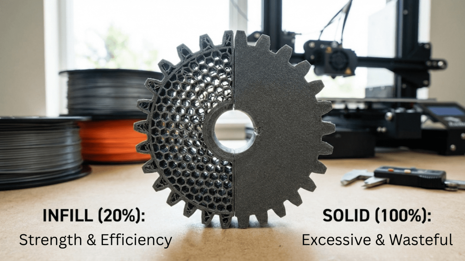
One of the most counterintuitive concepts that newcomers to three-dimensional printing encounter involves the realization that printed objects do not need to be solid throughout their volume to function effectively. The internal structure of most 3D printed parts consists of a partially hollow honeycomb or lattice arrangement that provides adequate strength while consuming only a fraction of the material and time that completely solid construction would require. This internal structure, called infill, represents one of the key differences between additive manufacturing and traditional production methods that typically create inherently solid parts.
Understanding infill requires recognizing that the strength and rigidity of an object depend more on its outer shell and geometric form than on whether its interior is completely filled with material. Just as structural steel beams use I-beam cross-sections with hollow centers rather than solid rectangles, and just as bones in nature use internal lattice structures rather than solid construction, 3D printed parts achieve better strength-to-weight ratios through intelligent internal structures than through brute-force solid filling. The mathematical principle behind this efficiency is that bending stiffness depends primarily on material distance from neutral axes, making properly designed hollow structures superior to solid ones on a per-weight basis.
The term “infill” describes the internal pattern that fills the volume between outer walls of a printed part. While the exterior surfaces must be solid to contain the internal structure and provide a finished appearance, the interior can use any of numerous geometric patterns at varying densities that provide structural support while leaving significant air spaces. A typical setting might be twenty percent infill, meaning that twenty percent of the internal volume contains solid material while eighty percent remains as air gaps within the supporting lattice. This sparse internal structure prints much faster than solid filling while providing strength adequate for most applications.
The practical implications of infill optimization extend beyond just material savings to encompass print time reduction, improved part behavior in some applications, and design flexibility that solid construction cannot match. Parts with lower infill weigh less, which matters for applications where weight is critical. They use less filament, which matters when material costs are significant or when expensive specialty filaments are required. They print faster, which matters when time is limited or when producing multiple copies. Understanding how to configure infill appropriately for specific applications separates efficient printing from wasteful practices that consume unnecessary time and material.
This comprehensive guide will explore what infill is and how it functions structurally, why solid prints are usually unnecessary and often undesirable, what different infill patterns exist and their relative strengths, how infill density affects mechanical properties and print characteristics, how to select appropriate infill for different applications, what advanced infill techniques exist, and how infill interacts with other print parameters. Whether printing decorative objects, functional prototypes, or engineering parts, mastering infill configuration enables producing parts that meet requirements efficiently without waste.
Understanding Infill: The Internal Structure of Prints
To grasp why infill works and how to use it effectively, examining what infill actually consists of and how it provides structural support reveals the principles that make sparse internal structures viable for most applications.
Infill consists of repetitive geometric patterns that extend through the interior volume of printed parts between the outer perimeter walls and the solid top and bottom surfaces. These patterns typically use straight lines, zigzag paths, or more complex geometries arranged in regular grids, hexagons, or three-dimensional lattices. The pattern repeats at a scale defined by the infill line spacing, creating a structure that resembles scaffolding or framework supporting the outer shell.
The mechanical function of infill primarily involves supporting the top surfaces of prints to prevent them from sagging into the hollow interior. Without internal support, top surfaces that should close over hollow volumes would collapse inward during printing because nothing supports the material being deposited into space. The infill provides periodic support points that hold up the top layers as they bridge between supports, allowing the top surface to close over the internal volume. Secondary functions include providing some resistance to crushing forces applied perpendicular to the shell and adding rigidity that resists flexing of the outer walls.
The density of infill expresses as a percentage indicating what fraction of the internal volume contains solid material versus air gaps. Zero percent infill creates completely hollow parts with only perimeter walls. One hundred percent infill makes entirely solid parts. Intermediate values create partially filled interiors with the specified ratio of material to air. Twenty percent infill is common for general purposes, meaning one-fifth of the interior volume has plastic and four-fifths has air. Higher percentages increase strength and weight proportionally, while lower percentages maximize material savings and speed.
The infill line spacing determines how far apart adjacent infill lines or struts are positioned. This spacing inversely correlates with infill density—denser infill requires closer spacing, while sparse infill uses wider spacing. Typical spacing might range from two to ten millimeters between adjacent infill lines depending on density settings. The spacing affects how far the top surface must bridge between support points, with wider spacing creating longer unsupported spans that are more challenging to bridge successfully.
The distinction between infill and perimeters clarifies that infill represents internal structure while perimeters form the exterior shell. Slicing software first traces outer and inner perimeter walls to create the shell, then fills the interior region bounded by the inner perimeter with the selected infill pattern. The number of perimeter walls, typically two to four, determines shell thickness independently from infill settings. Strong shells with sparse infill create lightweight structures, while thin shells with dense infill create heavy parts with potentially weak surfaces.
Top and bottom solid layers override infill settings at the extremes of parts to create continuous surfaces that close the structure. Rather than extending the infill pattern to the very top and bottom which would create porous surfaces with holes, slicing software generates multiple solid layers at these locations. The number of top and bottom layers, commonly four to six, ensures infill remains completely hidden and surfaces appear solid. These solid layers bridge across the infill supports, relying on the infill to prevent sagging.
The three-dimensional nature of some infill patterns creates structures that extend through multiple layers rather than simply repeating the same two-dimensional pattern at each layer height. These 3D patterns like gyroid, cubic, or octet create true three-dimensional lattices with members connecting between layers. The result is a space-filling structure that potentially offers better strength and isotropy compared to 2D patterns that may show weakness between layers.
Why Solid Prints Are Usually Unnecessary
The common assumption that stronger or better parts require solid construction throughout proves false for most applications, with sparse infill providing adequate performance while offering numerous practical advantages. Understanding why solid filling is rarely optimal helps avoid the wasteful practice of printing everything at one hundred percent density.
Structural efficiency explains why hollow structures with proper internal support often outperform solid blocks of equivalent weight. Consider two parts of identical outer dimensions, one solid and one with twenty percent infill. The hollow part weighs perhaps thirty percent of the solid part’s weight due to the material savings from sparse infill. For the same total weight, the hollow part could be made with proportionally thicker walls, creating a structure with much greater bending stiffness and strength than the solid block. This principle drives why natural structures like bones use internal lattice construction and why engineered structures like aircraft use honeycomb cores rather than solid construction.
Material waste from solid printing consumes filament that provides minimal benefit beyond what appropriate infill achieves. The marginal strength gained from increasing infill from thirty percent to one hundred percent rarely justifies the more than triple material consumption and print time. Most applications do not stress parts sufficiently that the difference between thirty and one hundred percent infill matters functionally. The additional material becomes waste that adds cost without adding value.
Print time increases dramatically with higher infill because more material must be deposited. A part at twenty percent infill might complete in six hours, while the same part at one hundred percent infill could require twelve to fifteen hours due to the additional material and the typically slower speed used for filling dense interiors. This time difference multiplies across many prints, representing substantial productivity loss from unnecessary solid filling. Time is particularly valuable in prototyping where rapid iteration matters more than absolute maximum strength.
Heat dissipation challenges arise in solid prints because thick solid masses cool slowly and unevenly, creating internal stresses. The exterior surfaces cool first, potentially cracking from stresses as the hot interior continues shrinking. Warping becomes more likely with solid prints due to the greater thermal mass and temperature gradients. Sparse infill with air gaps promotes more even cooling by allowing heat to escape through the internal structure, reducing warping tendency and internal stress buildup.
Dimensional accuracy can suffer in solid prints because the cooling behavior differs from typical infill patterns. Solid regions may shrink differently than regions with standard infill, causing dimensional variations and potentially warping that distorts geometry. Many slicers calibrate their settings assuming typical infill densities, and solid filling may behave differently than these calibrations expect, leading to unexpected results.
Weight considerations matter for many applications where lighter parts perform better. Robotics, drones, prosthetics, and numerous other applications benefit from weight reduction that infill provides compared to solid construction. Even when strength is required, achieving it through optimized geometry with hollow construction produces better strength-to-weight ratios than solid parts that carry unnecessary mass.
Material properties sometimes improve with moderate infill compared to solid construction. Flexible materials particularly benefit from sparse infill that allows the part to flex more naturally than solid construction would. The breathing room that infill air gaps provide accommodates material expansion from heat or moisture absorption better than solid construction that might crack from such stresses.
Special effects like translucency can be achieved through sparse infill in transparent materials, creating interesting visual effects as light filters through the internal structure. Completely solid parts in transparent materials appear nearly opaque due to light scattering at internal boundaries, while structured infill creates controlled optical properties.
Infill Patterns: Comparing Different Geometries
Slicing software offers numerous infill pattern options, each with distinct structural characteristics, printing behaviors, and appropriate use cases. Understanding these patterns enables selecting optimal internal structures for specific requirements.
Rectilinear or grid infill represents the simplest pattern, consisting of parallel lines alternating direction at each layer. One layer has lines running in one direction, the next layer has perpendicular lines, creating a square grid when viewed from above. This pattern prints very quickly because it consists of long straight paths without complex geometry. The structural properties show directional weakness since strength depends heavily on whether loads align with or perpendicular to the line directions at any given layer. Rectilinear works well for non-critical parts where speed matters more than strength optimization.
Honeycomb or hexagonal infill creates a pattern resembling bee honeycomb, with hexagonal cells that efficiently use material while providing relatively uniform strength in the horizontal plane. Hexagons efficiently tile two-dimensional space while approaching the strength distribution of circles. This pattern requires slightly more complex tool paths than rectilinear, printing somewhat slower but offering better isotropy in the horizontal plane. Honeycomb became popular for balanced properties but newer patterns often provide better performance.
Triangular infill uses equilateral triangles tessellated across the build area. Triangles provide excellent rigidity because the geometry naturally resists deformation—any attempt to deform a triangle requires either stretching or compressing the members. This pattern offers good strength but prints slowly due to the many direction changes required to trace triangular paths. The small triangular cells also mean relatively high material usage for given density percentages.
Gyroid infill creates a three-dimensional wavy pattern based on mathematical minimal surfaces. This pattern provides excellent strength in all directions with good isotropy, making it popular for structural parts. The flowing wavy geometry distributes stress well and the 3D nature means strength does not depend purely on in-plane directions as 2D patterns do. Gyroid prints reasonably quickly despite the curving paths because the long continuous curves avoid the constant direction changes that slow other patterns.
Cubic infill generates a true three-dimensional lattice with diagonal struts connecting in all directions. The cube structure provides isotropic strength since members extend in multiple directions through the volume. This pattern excels for parts needing strength in arbitrary directions but uses relatively more material than some alternatives at equivalent density settings. The computational cost of generating cubic infill can slow slicing for very complex models.
Octet infill combines tetrahedra and octahedra into a space-filling three-dimensional lattice. This pattern ranks among the strongest infill options per weight, with excellent isotropy and efficient material usage. The complex geometry requires sophisticated slicing calculations and prints somewhat slowly, but the structural efficiency justifies these costs for demanding applications requiring maximum strength from limited material.
Line infill represents the simplest possible pattern, just parallel lines in a single direction that never change. This unidirectional infill prints extremely quickly and uses minimal material for its density percentage. However, it provides strength only parallel to the lines with essentially no strength perpendicular to them. Line infill suits applications where load direction is known and controlled, allowing efficient material use by aligning lines with stress directions.
Concentric infill follows the part’s outline, creating nested perimeters that gradually fill inward from the outer walls. This pattern suits organic shapes where following contours makes sense structurally and may reduce print time compared to patterns that must fill arbitrary internal shapes. The concentric nature makes this pattern essentially unidirectional at any given location, creating directional strength characteristics.
Cross and cross 3D patterns create structures with perpendicular members forming plus signs in two or three dimensions. These patterns optimize for flexibility while maintaining some strength, making them appropriate for parts that must flex without breaking. The open structure compresses easily but resists tensile forces reasonably well, creating characteristics useful for rubber-like behaviors in rigid materials.
Selecting Appropriate Infill Density
Choosing the right infill density involves balancing strength requirements against material consumption and print time. No universal optimal density exists, with appropriate values ranging from zero to one hundred percent depending on application specifics.
Zero to five percent infill creates nearly hollow parts with minimal internal structure, appropriate for parts that do not experience significant loads and where appearance only matters. Decorative objects, display models, or lightweight enclosures often work fine with minimal infill. The risk is that wide top surface spans may sag without sufficient support, requiring attention to top layer settings and testing to ensure successful bridging over such sparse support.
Ten to twenty percent infill represents common settings for general-purpose printing where moderate strength suffices. This range provides adequate support for top surfaces, reasonable structural integrity for handling and use, and significant time and material savings compared to denser options. Many default printer profiles suggest fifteen to twenty percent as balanced compromises. Parts in this range feel solid when handled but are obviously not heavy like fully dense prints.
Twenty-five to forty percent infill increases strength substantially while maintaining reasonable material efficiency. Parts needing to withstand moderate forces like functional prototypes, tools, or mechanical components often use these densities. The incremental strength gain becomes more expensive in terms of time and material as density increases, but the parts approach the robustness of solid construction for many loading conditions.
Fifty to seventy-five percent infill creates quite robust parts approaching solid construction in many properties. These high densities suit structural components, parts under high stress, or situations where absolutely maximizing strength justifies the time and material costs. The diminishing returns become obvious at these densities, with each additional percentage providing less marginal strength benefit while linearly increasing material usage and time.
Eighty to one hundred percent infill produces essentially solid parts with minimal or no air gaps internally. Such densities are rarely necessary but may suit situations like parts requiring maximum rigidity, components exposed to high pressures, or parts that will undergo extensive post-processing like machining or carving where internal voids would create problems. The massive time and material investment for these densities should be justified by genuine functional requirements.
Variable infill density allows different densities in different regions of the same part. Slicing software can apply modifiers that specify higher density where stress concentrates or where strength is critical while using lower density in less-stressed regions. This optimization minimizes overall material and time while providing strength where needed. Manually specifying these regions requires understanding the load cases and stress distribution in the part.
Infill overlap settings control how much infill extends into the perimeter walls, affecting bonding between infill and shells. Insufficient overlap creates gaps that weaken the part and may allow infill to show through walls. Excessive overlap wastes material and may create surface bulges. Typical overlap of ten to twenty percent of infill line width ensures good bonding while minimizing waste.
Gradual infill steps allow density to decrease from outer surfaces inward. The areas near the shell have higher density that gradually reduces toward the part’s center. This gradient distribution efficiently uses material by concentrating it where stresses are typically higher near surfaces while minimizing material in the typically lower-stress core region.
How Infill Affects Print Characteristics Beyond Strength
While strength considerations drive many infill decisions, numerous other aspects of print behavior and part characteristics depend on infill configuration. Understanding these secondary effects enables optimizing for diverse requirements beyond pure structural performance.
Print time correlates strongly with infill density because denser infill requires depositing more material across more area. The relationship is roughly linear, with twenty percent infill requiring roughly twenty percent of the time that one hundred percent infill demands, all else equal. However, infill often prints faster than perimeters, so the actual time relationship depends on the ratio of surface area to volume. Small parts with high surface-to-volume ratios spend relatively more time on perimeters regardless of infill, while large simple parts with lower ratios see infill time dominate.
Material consumption scales directly with infill density, making density selection important for expensive materials or high-volume production. The cost difference between fifteen and thirty percent infill doubles material usage, which multiplies across hundreds of parts. For exotic filaments costing hundreds of dollars per kilogram, infill optimization provides direct cost savings. Even for cheap commodity filament, material waste from excessive infill accumulates over time.
Surface quality can be affected by infill showing through outer walls as a phenomenon called “pillowing” or “infill pattern visibility.” When infill lines are too wide or when overlap is insufficient, the infill pattern may telegraph through to visible surfaces as texture or ripples. Sparse infill with wide line spacing exacerbates this problem. Using adequate perimeter walls, appropriate overlap, and not excessively sparse infill prevents infill from affecting surface appearance.
Warping tendency increases with infill density because more material means more thermal mass that cools slowly and contracts significantly. Solid or very dense parts warp more readily than hollow or sparse parts. The internal structure’s pattern also matters, with some patterns creating directional stresses that promote warping in specific directions. Using moderate infill helps manage warping in materials prone to thermal contraction issues.
Flexibility and compliance vary with infill density and pattern. Sparse infill allows parts to flex more readily than dense infill because the air gaps compress when force is applied. The infill pattern determines whether parts flex isotropically or show directional flexibility. For applications requiring controlled flexibility like living hinges or compliant mechanisms, infill configuration provides a tuning parameter that adjusts mechanical behavior.
Acoustic properties including whether parts sound hollow when tapped depend on internal structure. Solid parts produce dull thuds, while hollow parts ring or sound empty. The difference is purely cosmetic for most applications but might matter when parts should feel substantial. Higher infill creates more solid-sounding parts without requiring true solid construction.
Thermal properties including heat capacity and insulation characteristics depend on infill density. Sparse infill creates parts with air gaps that provide insulation, while dense infill conducts heat more readily. Applications involving temperature management may benefit from specific infill configurations that optimize thermal behavior.
Buoyancy and water resistance vary with infill because air trapped in internal voids affects density and may provide flotation. Parts that must float need low infill, while parts that must sink need high infill. Water resistance is poor regardless of infill if parts are not sealed, as FDM printing creates microscopic gaps between layers that allow water penetration. However, infill density affects how much water the part can absorb before saturation.
Post-processing behavior differs between infill densities. Sanding, painting, or other surface treatments work similarly regardless of infill, but operations like machining, drilling, or tapping threads are affected. Drilling into sparse infill may break through into voids, while dense infill provides solid material for threads. Planning post-processing requirements influences whether higher infill is beneficial.
Advanced Infill Techniques and Optimization
Beyond simply selecting a pattern and density, advanced infill strategies optimize internal structures for specific requirements or enable capabilities that basic settings cannot achieve. These techniques require understanding both the software capabilities and the structural principles involved.
Support infill serves the sole purpose of preventing top surfaces from sagging into voids and is not intended to provide structural strength. This recognition allows using very sparse, fast-printing support infill like rectilinear or lightning patterns that efficiently prevent sagging while minimizing time and material. Structural loading is handled by the shell walls rather than infill, so elaborate strong infill patterns may be unnecessary for many applications.
Lightning infill represents an extreme optimization of support infill principles. This pattern generates branching tree-like structures that reach only where needed to support top surfaces, leaving maximum air gaps and using minimal material. Lightning infill can reduce infill material usage by fifty percent or more compared to conventional patterns while adequately preventing top surface sagging. The time savings are proportional to material savings. This pattern suits large parts where conventional infill would consume excessive time and material providing unnecessary structure.
Modifier mesh techniques allow specifying different infill settings for different regions within a single part. A part might use five percent infill in most of its volume but fifty percent infill in regions where stresses concentrate or where structural requirements are higher. Manually placing modifier meshes requires understanding the loading conditions but allows significant optimization. Some software provides tools for automatically identifying high-stress regions through analysis and applying appropriate modifiers.
Infill combining strategies use different patterns in different regions based on their characteristics. A part might use fast simple patterns like rectilinear in large open regions where speed matters but use strong patterns like gyroid near surfaces where the infill might be exposed by drilling or machining. These hybrid approaches optimize locally while maintaining overall efficiency.
Minimum infill area settings prevent generating infill in very small interior voids where the infill would provide negligible benefit but consume time. Regions below a specified area threshold remain completely hollow rather than being filled with infill. This optimization recognizes that tiny voids gain little from infill while generating such infill creates many short segments that slow printing.
Monotonic infill ordering ensures infill lines orient consistently in a single direction rather than alternating, creating more uniform top surface appearance where infill might show through. This setting sacrifices some structural isotropy for improved aesthetics when the part’s surfaces matter more than internal structure.
Ironing over infill creates smoother top surfaces by passing a hot nozzle over completed top layers, melting and smoothing any irregularities. The process works better over denser infill that provides solid support for the ironing passes. Sparse infill may not support ironing well because the lack of solid support allows the nozzle to push material down into voids.
Infill travel optimization reduces non-productive moves between infill regions. The slicer analyzes the infill pattern to find efficient sequencing that minimizes the total travel distance. These travel moves represent wasted time where no material deposits, so reducing them improves overall print time even without changing infill parameters themselves.
Conclusion
Infill represents one of the most important optimizations available in three-dimensional printing, enabling creation of parts that are strong enough for their intended purposes while using only a fraction of the material and time that solid construction would require. Understanding that internal structure can be sparse without compromising function separates efficient printing from wasteful practices that produce unnecessarily heavy, expensive, and time-consuming parts.
The principle that properly designed hollow structures outperform solid construction on a weight-normalized basis explains why moderate infill densities of fifteen to thirty percent provide adequate strength for most applications. The outer shell contributes far more to bending stiffness and strength than internal filling, making investment in robust shells with sparse infill superior to thin shells with dense infill. This structural efficiency mirrors nature’s designs in bone structure and engineering practice in aerospace construction.
Different infill patterns offer distinct tradeoffs between print speed, material efficiency, isotropy, and pure strength. Simple patterns like rectilinear print quickly but lack structural sophistication. Advanced patterns like gyroid provide excellent strength per weight with good isotropy but require more complex tool paths. Selecting appropriate patterns depends on whether the application demands speed, strength, or specific directional properties.
Infill density selection requires balancing functional requirements against practical constraints on time and material. Very sparse infill approaching zero percent suits purely decorative applications. Moderate densities around twenty percent handle typical structural requirements. Dense infill above fifty percent is rarely necessary and should be justified by genuine functional needs rather than assumed necessity. Variable density techniques allow concentrating material where needed while maintaining overall efficiency.
The secondary effects of infill on print time, material consumption, warping behavior, flexibility, and numerous other characteristics mean that infill configuration influences far more than just structural strength. Understanding these broader implications enables using infill as a multi-faceted optimization tool that tunes overall part behavior rather than simply filling space inside shells.
Advanced techniques including lightning infill, regional modifiers, pattern combining, and intelligent optimization push infill efficiency beyond what basic density and pattern selection achieve. These approaches require deeper understanding and more sophisticated software but enable creating parts that maximize performance while minimizing resource consumption. As slicing software continues evolving, infill optimization will likely become increasingly sophisticated and automated.
Mastering infill configuration represents essential knowledge for efficient 3D printing. The ability to produce parts that are strong enough, light enough, and completed quickly enough while consuming minimal material separates skilled users who optimize effectively from beginners who waste resources through inappropriate settings. Whether printing decorative objects, functional prototypes, or engineering components, intelligent infill selection ensures that each part uses resources proportional to actual requirements rather than defaulting to wasteful solid construction that provides minimal benefit at substantial cost.