Introduction
Imagine you are building a sculpture from sheets of paper stacked one on top of another, with each sheet representing a horizontal cross-section of the final form. The thickness of each individual sheet determines how smoothly the stacked layers approximate curves and angled surfaces. Thin sheets allow capturing subtle contours with many closely-spaced layers, while thick sheets create a coarser approximation with fewer, more widely-spaced layers. This analogy captures the essence of layer height in three-dimensional printing, one of the most fundamental parameters that affects virtually every aspect of how prints turn out.
Layer height represents the vertical thickness of each individual layer that the printer deposits as it builds objects incrementally from bottom to top. This single measurement, typically specified in fractions of a millimeter, ripples through the printing process to affect surface smoothness, print time, mechanical strength, feature resolution, and the fundamental appearance of finished parts. Understanding layer height and its wide-ranging effects empowers you to make informed decisions about this critical setting rather than simply accepting whatever default value your slicing software suggests.
The concept might seem straightforward at first consideration—thinner layers create smoother surfaces while thicker layers print faster—but the full picture involves nuanced interactions between layer height and numerous other aspects of printing. The relationship between layer height and print time is not perfectly linear. Layer height affects not just appearance but also the mechanical properties of printed parts through its influence on layer bonding. The optimal layer height for any given print depends on what characteristics matter most for that specific application, whether appearance, speed, strength, or the ability to reproduce fine details.
Different printing technologies handle layer height somewhat differently, though the fundamental principle of building objects through stacked layers remains universal. FDM printers typically offer layer height adjustments from around fifty micrometers up to several hundred micrometers, with common values ranging from 0.1 to 0.3 millimeters. Resin printers often use thinner layers, sometimes as fine as twenty-five micrometers, because their layer exposure process allows such precision without proportional time increases. Understanding how layer height works in your specific technology helps set appropriate expectations and make effective configuration choices.
This comprehensive exploration will walk through what layer height actually means in physical terms, how it affects every major characteristic of printed parts, what constraints limit usable layer heights for different situations, how to choose appropriate values for specific applications, what advanced techniques like variable layer height enable, and how layer height interacts with other critical print settings. Think of this as building a complete mental model of layer height from the ground up, starting with basic concepts and progressing toward sophisticated understanding that enables expert-level decision making about this foundational parameter.
Understanding Layer Height as a Physical Measurement
Before examining how layer height affects prints, establishing a clear mental picture of what layer height means physically helps ground the more abstract discussions that follow. Layer height is not a theoretical concept but a real, measurable dimension that you could verify with precise instruments by examining the cross-section of a printed part.
Consider a printed object under magnification where you can see the individual layers that comprise its structure. Each layer represents a thin horizontal slice of material that was deposited during one pass across that particular height. The vertical distance between the bottom surface of one layer and the bottom surface of the next layer up defines the layer height. If you printed at 0.2 millimeters layer height, examining the part’s cross-section would reveal layers stacked with their bottom surfaces spaced exactly 0.2 millimeters apart vertically.
The layer itself has physical thickness that results from material being deposited and spreading to a certain height. For FDM printing, when melted plastic extrudes from the nozzle and contacts either the build plate for the first layer or the previous layer for subsequent layers, it spreads and compresses to form a layer of specific thickness. The nozzle height above the previous layer, combined with the material’s properties and the extrusion rate, determines the resulting layer thickness. The printer must precisely control this height to ensure consistent layer thickness throughout the build.
The staircase effect that makes layer heights visible on angled or curved surfaces provides perhaps the most intuitive way to understand the concept. When a surface angles away from horizontal, each layer creates a small horizontal step. The vertical dimension of these steps equals the layer height. Imagine a ramp rising at forty-five degrees. Printing with 0.3 millimeters layer height creates steps where each one rises 0.3 millimeters vertically and extends 0.3 millimeters horizontally along the ramp’s surface. Reducing to 0.1 millimeters layer height makes each step only 0.1 millimeters in both dimensions, creating a smoother approximation of the continuous ramp surface with steps one-third the size.
The relationship to printer resolution helps contextualize layer height within the broader capabilities of the printing system. While layer height controls vertical resolution, the printer also has horizontal resolution determined by factors like nozzle size, positioning precision, and material behavior. A printer might achieve fifty micrometer layer heights vertically while having two-hundred micrometer resolution horizontally due to nozzle diameter. Understanding that layer height represents just one dimension of the printer’s overall resolution prevents unrealistic expectations about what thin layers can achieve when horizontal resolution limits overall detail.
The practical range of achievable layer heights depends on the printing technology and specific equipment capabilities. FDM printers typically cannot go below about twenty-five percent of the nozzle diameter for minimum layer height, as thinner layers risk the nozzle scraping through previously deposited material or failing to extrude consistently. Maximum layer height usually tops out around seventy-five percent of nozzle diameter, beyond which layers may not bond properly or the extruder cannot maintain adequate material flow. These constraints create a practical operating window within which layer height can be adjusted, typically around 0.05 to 0.35 millimeters for common 0.4 millimeters nozzles.
Think of layer height as analogous to the resolution setting when printing documents on paper, though the analogy is imperfect. Just as higher DPI creates sharper text and images but takes longer to print, finer layer heights create smoother three-dimensional surfaces but extend print times. However, unlike two-dimensional printing where resolution primarily affects appearance, three-dimensional layer height influences structural properties and manufacturability alongside aesthetics, making the decision more complex than simply choosing the finest resolution possible.
How Layer Height Affects Surface Quality and Appearance
The most immediately visible impact of layer height shows in the surface quality of printed parts. Understanding this relationship in detail helps predict how different layer heights will affect the appearance of specific geometries and guides decisions about when surface quality justifies the time investment of thin layers.
The visibility of layer lines on curved and angled surfaces scales directly with layer height. Each layer creates a visible ridge at its boundary where it transitions to the next layer above. On perfectly horizontal surfaces, these ridges remain invisible because you view them from above where the flat top of each layer presents a smooth appearance. On perfectly vertical surfaces, layer lines also remain relatively subtle because the thin edge of each layer presents minimal visible surface area. However, on surfaces angled between horizontal and vertical, each layer creates a pronounced step that catches light and creates the characteristic ribbed texture of three-dimensional printed objects.
The mathematics of this step visibility reveals why certain angles show layer lines more prominently than others. A surface angled at forty-five degrees from horizontal creates steps where the vertical and horizontal dimensions equal the layer height. At shallower angles closer to horizontal, the horizontal dimension of each step increases while the vertical dimension stays constant, creating long shallow steps. At steeper angles approaching vertical, the horizontal dimension decreases while vertical remains constant, creating short tall steps. The most prominent layer lines typically appear at angles around thirty to sixty degrees where the step proportions create maximum visibility.
Surface smoothness on organic or curved shapes benefits dramatically from thinner layers because curves require many small steps to approximate smoothly. Consider printing a sphere. Thick layers create an obviously faceted approximation where individual steps are clearly visible, creating something that looks more like a faceted gem than a smooth sphere. Thin layers create much smaller steps that blend together visually into an apparently smooth curve when viewed from normal distances. The improvement in smoothness is not linear with layer height reduction—cutting layer height in half might make surfaces appear three or four times smoother because of how human vision integrates the smaller steps into perceived continuity.
The interaction between layer height and lighting conditions affects how obviously layer lines appear in finished parts. Grazing light that strikes surfaces at shallow angles emphasizes every small irregularity including layer lines, making them more visible. Diffuse lighting from multiple directions tends to soften the appearance of layer lines by reducing the shadows that make them distinct. When choosing layer heights for parts that will be displayed under specific lighting, considering how that lighting will interact with surface texture helps determine what layer height produces acceptable appearance.
Post-processing potential varies with layer height because deeper layer lines require more aggressive sanding or other finishing to remove. Parts printed with 0.3 millimeters layers need substantial sanding starting with coarse grits to eliminate the pronounced ridges before progressing to fine grits for smoothness. Parts printed at 0.1 millimeters layers might need only light sanding with medium grits to achieve smoothness, or might look acceptable without any sanding depending on the application. If you plan to sand parts anyway, printing with thicker layers to save time makes sense because the sanding will eliminate surface texture regardless. If parts should look good directly from the printer without post-processing, thin layers become more important.
The subjective perception of quality correlates strongly with layer height for most observers. People unfamiliar with three-dimensional printing often judge print quality primarily by whether they can see layer lines, equating visible layers with low quality and smooth surfaces with high quality. This perception might not align with technical reality—a part with visible layer lines might be perfectly functional and structurally sound—but appearance shapes perception nonetheless. For parts that will be seen by others or represent your work quality, the appearance benefits of thin layers often justify the extra time investment.
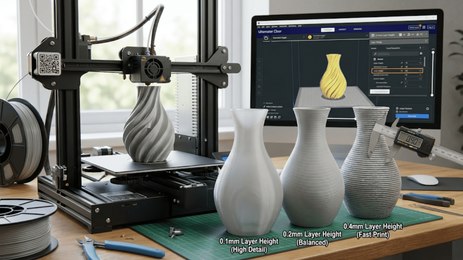
Consider two identical vases printed at different layer heights to make this concrete. The vase printed at 0.3 millimeters shows obvious horizontal ridges across its curved surfaces, creating texture that catches light and clearly reveals the layer-by-layer construction method. The same vase printed at 0.1 millimeters presents much smoother surfaces where layer lines remain visible on close inspection but appear nearly smooth from normal viewing distances. The thin-layer version took three times longer to print but looks dramatically better, demonstrating why layer height ranks among the most impactful quality settings.
The Relationship Between Layer Height and Print Time
Understanding exactly how layer height affects print time requires looking beyond the simple observation that thinner layers take longer because more layers are needed. The relationship involves several interconnected factors that make the time impact more complex than simple proportional scaling.
The direct relationship comes from the number of layers required to build any given height. An object standing one hundred millimeters tall needs one thousand layers at 0.1 millimeters layer height, five hundred layers at 0.2 millimeters, or three hundred thirty-three layers at 0.3 millimeters. Since each layer requires time for the print head to trace its paths and deposit material, doubling the layer count roughly doubles the total time. This creates the fundamental trade-off where thinner layers dramatically increase print time through the sheer multiplication of layers that must be printed.
However, the relationship is not perfectly linear because other factors change when layer height changes. Thinner layers typically require slower print speeds to ensure quality, as the precise positioning needed for very thin layers can be compromised by excessive speed. Thicker layers can often sustain faster speeds because the larger layer dimensions tolerate slight positioning imperfections better. This speed adjustment means cutting layer height in half might more than double print time if speeds must also reduce to maintain quality with the finer layers.
The per-layer overhead adds fixed time to each layer that becomes more significant with thin layers. Each layer involves time for the print head to return to starting position, time for retraction and priming operations, and time for speed changes at layer transitions. This overhead might only be a few seconds per layer, but it adds up when thousands of layers are involved. A print with five hundred layers at 0.2 millimeters might spend twenty-five minutes on per-layer overhead (three seconds per layer). The same part printed at 0.1 millimeters with one thousand layers spends fifty minutes on the same overhead, adding twenty-five minutes purely from the increased layer count even before considering the time to actually print each layer.
The volumetric flow rate creates constraints on how quickly material can be deposited regardless of layer height. FDM hotends can only melt and extrude plastic at certain maximum rates measured in cubic millimeters per second. Thicker layers require extruding more material per unit length of travel, potentially pushing against this flow rate limit. When print speeds would require flow rates exceeding the hotend’s capacity, either speed must reduce or the print will suffer from under-extrusion. This means very thick layers might not actually save as much time as proportional scaling would suggest because flow rate limits prevent using the highest speeds that thin layers allow.
The practical time scaling for typical layer height changes helps set realistic expectations. Changing from 0.2 millimeters to 0.1 millimeters typically increases print time by a factor of 2.2 to 2.5 rather than exactly 2.0 due to the speed reductions and per-layer overhead. Going from 0.2 to 0.3 millimeters might reduce print time by a factor of 0.6 to 0.7 rather than the proportional 0.67 if flow rate limits prevent full speed increases. These rough multipliers help estimate time impacts when considering layer height changes without requiring detailed analysis.
The percentage impact varies with part geometry because the ratio of time spent on perimeters versus infill versus top and bottom surfaces differs between parts. A hollow shell with mostly perimeter and minimal infill spends most print time tracing outlines that scale proportionally with layer count. A mostly-solid part with substantial infill spends more time on interior fill that might print faster with thicker layers and slower with thin layers. Understanding your specific part’s geometry helps predict whether layer height changes will have near-proportional time impacts or more complex effects.
Consider a practical example where you are printing a figurine at 0.2 millimeters layer height with an estimated time of six hours. Reducing to 0.15 millimeters increases layers by 33 percent and reduces speeds slightly, yielding perhaps eight hours total—not the perfectly proportional eight hours that 33 percent more layers would suggest in ideal scaling. Increasing to 0.28 millimeters reduces layers by 30 percent and allows some speed increase, yielding perhaps four hours total, again not matching perfect proportional scaling. These real-world deviations from simple math matter when planning prints around available time.
Layer Height’s Impact on Mechanical Strength and Properties
Beyond affecting appearance and print time, layer height influences the mechanical properties and structural strength of printed parts through its effects on layer bonding, failure modes, and stress distribution. Understanding these structural implications helps optimize layer height for functional parts where strength matters as much as or more than appearance.
Layer bonding represents the primary mechanism through which layer height affects strength. When FDM printing deposits a new layer atop the previous layer, the hot plastic of the new layer partially melts the surface of the previous layer, creating molecular entanglement and bonding as both cool together. Thinner layers maintain the previous layer at higher temperature when the new layer deposits because less cooling time elapses between layers. This hotter surface enables better intermolecular bonding across the layer boundary. Thicker layers allow more cooling time, potentially reducing bond strength if the previous layer cools too much before the next layer adds heat.
The anisotropic strength of FDM parts, meaning they are weaker in some directions than others, relates directly to layer height through the layer bonding mechanism. Parts loaded along the layer direction, pulling layers apart, rely entirely on the strength of layer-to-layer bonds rather than the intrinsic strength of the solid plastic. These bonds represent the weak links, and parts typically fail by delamination between layers when loaded in this direction. Parts loaded perpendicular to layers, compressing or tensing within individual layers, approach the strength of solid plastic because failure must either compress filaments within layers or shear across many layers simultaneously. The ratio between these strength directions changes with layer height.
Thinner layers generally provide superior layer-to-layer strength for several reasons beyond just the bonding temperature effect. The larger number of layer interfaces means failure must delaminate across more individual bonds even if each bond is slightly weaker. The reduced step between layers creates better mechanical interlocking through surface roughness at layer boundaries. The smaller layer heights also reduce stress concentrations at layer boundaries that can initiate failures. Experimental testing consistently shows improved tensile strength in the layer direction when using finer layer heights, though the improvement may only be ten to twenty percent rather than doubling strength.
The impact on functional parts varies with how loads apply. Parts experiencing primarily compressive loads or loads within layer planes show minimal strength difference between layer heights because they do not stress the layer bonds. Parts experiencing tensile loads perpendicular to layers, bending loads that create alternating tension and compression across layers, or impact loads that can propagate cracks between layers all show meaningful strength improvements from finer layers. Understanding the loading conditions allows targeting layer height optimization where it provides the most benefit.
Thick layers can actually provide advantages for certain structural applications despite generally weaker layer bonding. The reduced number of layer interfaces means fewer potential failure initiation sites. The larger layer dimensions can bridge small voids or imperfections more effectively than thin layers. For very large prints where layer bonding is adequate and bulk material properties matter more than layer interfaces, thick layers that print quickly might be entirely appropriate. Not every application demands maximum layer-to-layer strength.
The brittleness and ductility of printed parts show subtle dependencies on layer height through the crack propagation mechanisms. Thin layers with many interfaces can sometimes arrest crack propagation by forcing cracks to navigate between layers rather than propagating straight through solid material. Thick layers with fewer interfaces provide fewer opportunities for deflecting cracks. However, weak layer bonding in either case creates easy delamination paths that reduce effective toughness. The relationships are complex enough that predicting ductility from layer height alone proves unreliable without considering material properties and part geometry.
Consider printing a load-bearing bracket that will hold shelving. Using 0.1 millimeters layers might provide fifteen percent greater strength against the pulling forces the bracket experiences compared to 0.3 millimeters layers, while taking three times longer to print. Whether this strength increase justifies the time cost depends on how close to failure the design operates. If safety factors are large, the thicker faster layers work fine. If the bracket operates near its strength limits, the improved layer bonding from thin layers provides important margin.
Choosing Optimal Layer Height for Different Applications
With understanding of how layer height affects quality, time, and strength established, making informed layer height choices for specific applications requires balancing these competing factors based on what characteristics matter most for each particular use case. Different applications have different optimal points in the trade-off space.
Display models and artistic prints prioritize appearance above almost all other considerations. These parts might never experience mechanical loads beyond being handled carefully, making strength less critical than looking good. For such applications, thin layers that minimize visible layer lines provide clear benefits worth the extra print time. Layer heights of 0.1 millimeters or even finer when printing small detailed models help achieve the smooth surfaces that make prints look professional and finished rather than obviously three-dimensional printed. The time investment pays off in presentation quality that reflects well on your skills and the technology’s capabilities.
Functional prototypes for design validation occupy a middle ground where both speed and reasonable quality matter. These parts need to look good enough to evaluate aesthetics and proportion but do not require perfect surface finish since they are temporary tools for development rather than final products. Layer heights around 0.2 millimeters provide acceptable appearance for most prototype evaluation while printing reasonably quickly to enable rapid iteration. If surface quality becomes critical during validation, specific parts can be reprinted at finer layers while the bulk of prototype iterations use faster medium layers.
Mechanical parts and functional components prioritize strength and dimensional accuracy over appearance. These parts experience loads during use and must not fail, making layer bonding important. However, they might be hidden inside assemblies where appearance does not matter. For such applications, layer height choices should optimize for the strength and accuracy needed while accepting rougher surfaces as irrelevant to function. This might mean 0.15 millimeters for small precise parts or 0.3 millimeters for large robust parts where the reduced layer count improves speed without compromising adequate strength.
Rough draft prints and concept models require only enough quality to evaluate basic forms and proportions. These prints might be thrown away after brief examination or serve purely to verify that designs print successfully before committing to slow high-quality final versions. Thick layers around 0.3 millimeters or even coarser make sense for rapid draft printing where speed dominates all other concerns. Getting results quickly to inform decisions matters more than quality that will be discarded anyway. Using draft prints to identify problems before slow final prints prevents wasting time on doomed high-quality attempts.
Large structural prints and furniture components involve massive print times where every hour saved compounds across dozens or hundreds of hours total. For a print requiring two hundred hours at 0.15 millimeters, using 0.3 millimeters instead might reduce time to one hundred hours—a full hundred hours saved. Whether the coarser surface finish is acceptable depends on the part’s visibility and any planned post-processing, but saving four days of print time creates strong motivation to accept rougher surfaces when possible. Very large prints often undergo substantial post-processing anyway, making as-printed surface quality less critical.
Small detailed miniatures and intricate models benefit most from the finest layers the printer can achieve because their small size and high detail density demand maximum resolution. A miniature figurine only fifty millimeters tall printed at 0.3 millimeters layers shows obvious stacking with only one hundred sixty-seven total layers creating a very coarse approximation. The same miniature at 0.05 millimeters layers uses one thousand layers that capture fine details like facial features, fingers, and clothing folds much more faithfully. The print time increases substantially, but the quality improvement on small detailed models justifies the investment.
Parts destined for post-processing through sanding, painting, or chemical smoothing can use thicker layers because the finishing operations will eliminate surface texture anyway. When you plan to spend time sanding a part smooth, printing it slowly with thin layers that will be sanded away wastes time without improving the final result. Thick fast layers get material onto the printer quickly, then sanding brings surfaces to desired smoothness. The total time from start to finished part may be lower with thick layers plus sanding than with thin layers that still require some surface preparation.
Creating a mental decision framework helps systematize these choices. Ask yourself: Will anyone see this part’s surfaces? If yes, thin layers. If no, thick layers. Will this part experience significant mechanical loads? If yes, consider medium to thin layers for strength. If no, any layer height works structurally. How quickly do I need results? If urgent, thick layers. If time permits, thin layers. Stepping through these questions for each print guides toward appropriate layer heights rather than using the same setting mindlessly for every application.
Variable Layer Height and Adaptive Slicing
Beyond using uniform layer height throughout prints, advanced slicing software enables variable layer height that adapts to local geometry, using thin layers where detail matters and thick layers where speed helps. Understanding these adaptive techniques reveals opportunities to optimize prints beyond what single layer heights allow.
The concept behind variable layer height involves recognizing that different regions of models have different detail requirements. A model might include flat vertical walls that show minimal layer lines regardless of layer height, combined with curved domes that show pronounced stepping with thick layers. Using fine layers everywhere captures the dome’s curves beautifully but wastes time on the walls where coarse layers look identical. Using coarse layers everywhere prints quickly but makes the dome look faceted. Variable layer height uses coarse layers for walls and fine layers for curves, achieving good appearance where it matters while saving time where it does not.
Automatic detection algorithms in slicing software analyze model geometry to identify regions benefiting from fine layers versus accepting coarse layers. The software examines surface angles at each height, applying finer layers where surfaces change angle rapidly, indicating curves or complex geometry, and coarser layers where angles remain steady, indicating flat or gently sloping surfaces. This automatic analysis saves users from manually specifying where different layer heights should apply while achieving optimized results that balance quality and speed better than uniform layers.
Manual control over variable layer height allows overriding automatic decisions when you have specific knowledge about what regions matter most. Slicing software typically provides interfaces showing the automatically determined layer height variation along the vertical axis, with tools for adjusting the layer height at specific heights or ranges. You might manually specify that a particular height range containing fine text should use minimum layer height while surrounding structure uses thicker layers. This manual control enables optimizations that automatic algorithms cannot anticipate.
The smoothing and transition between different layer heights requires careful handling to avoid visible artifacts at heights where layer thickness changes. Abrupt changes from 0.1 millimeters to 0.3 millimeters layers create noticeable steps in surface texture. Good slicing software transitions gradually between different layer heights, perhaps stepping through 0.1, 0.15, 0.2, 0.25, and 0.3 millimeters over several layers rather than jumping directly from finest to coarsest. These gradual transitions blend the texture change, making layer height variations less obvious in finished parts.
The time savings from variable layer height can be substantial for parts with localized detail. A mechanical component might have precisely dimensioned mounting features at its base requiring fine layers for accuracy, with a simple prismatic body above that works fine with coarse layers. Using 0.1 millimeters layers for the first twenty millimeters and 0.3 millimeters for the remaining eighty millimeters might save forty percent of print time compared to using 0.1 throughout while maintaining quality where critical dimensions exist. These savings compound on large parts where optimization opportunities multiply.
The interaction with support structures deserves consideration because supports may benefit from different layer height strategies than the actual part. Some slicers allow specifying that supports should use coarser layers than the part itself since support surface quality is irrelevant as long as supports perform their structural function. This accelerates support printing, reducing total time while maintaining part quality. The technique works best when supports occupy significant volume, making their layer height meaningfully impact total time.
Practical application of variable layer height requires experimentation to develop intuition about what layer height variations your specific printer handles well and what regions benefit most from optimization. Start with automatic variable layer height on models that clearly have some simple and some complex regions. Examine the results and note where layer height changes create visible transitions and where they blend seamlessly. Over time, you will develop understanding of when variable layers provide worthwhile optimization versus when the added complexity is not worth the modest savings.
Consider printing a statue that combines a detailed face with a simple cylindrical pedestal base. Automatic variable layer height might use 0.08 millimeters on the face where curves and fine features demand resolution, transition to 0.2 millimeters on the torso, and use 0.3 millimeters on the simple pedestal. The result captures facial detail beautifully while saving substantial time on the simple base, delivering better results faster than any uniform layer height could achieve. This represents the power of adaptive approaches that tailor settings to local requirements.
The Interaction Between Layer Height and Other Print Settings
Layer height does not operate in isolation but interacts with numerous other print settings in ways that require coordinated adjustment for optimal results. Understanding these interactions prevents suboptimal prints resulting from changing layer height without adapting related settings accordingly.
Print speed and layer height are intimately related because the mechanical precision required to maintain quality varies with layer dimensions. Very thin layers demand precise positioning since small errors represent larger percentages of the layer height. Attempting to print 0.06 millimeters layers at one hundred millimeters per second risks positioning errors and vibration creating defects. Reducing speed to forty millimeters per second allows more precise positioning. Conversely, thick layers tolerate higher speeds because small positioning errors matter less relative to the large layer dimensions. The general principle suggests reducing speed by twenty to thirty percent when halving layer height to maintain equivalent quality.
Cooling settings require adjustment because layer cooling time directly affects layer bonding and overhangs. Thinner layers mean shorter time between depositing successive layers, giving less time for cooling before the next layer adds more heat. Increasing cooling fan speed helps each thin layer solidify before the next deposits. Thicker layers with more time between each layer may need less aggressive cooling since longer intervals allow more natural cooling. However, this must balance against overhang performance where insufficient cooling causes sagging regardless of layer height.
Extrusion multiplier or flow rate may need slight adjustment with different layer heights because the pressure required to extrude material varies with the cross-sectional area being deposited. Thin layers with smaller cross-sections require different pressure dynamics than thick layers with large cross-sections. Some users find that reducing flow by two to three percent when using very thin layers prevents slight over-extrusion, while increasing flow slightly with very thick layers ensures adequate material deposition. These adjustments are subtle but can improve results noticeably.
The number of top and bottom layers specified as solid surfaces should increase when using thinner layers to prevent infill from showing through. If 0.2 millimeters layers use four top layers totaling 0.8 millimeters of solid surface, switching to 0.1 millimeters layers should use eight top layers to maintain the same 0.8 millimeters solid thickness. Failing to adjust means thin-layer prints might show infill patterns through top surfaces because insufficient solid layers were specified. The adjustment scales proportionally with layer height changes.
First layer height often uses a thicker setting than subsequent layers regardless of the chosen standard layer height because thick first layers improve bed adhesion reliability. A print using 0.12 millimeters layers might use 0.2 millimeters for the first layer only, providing better adhesion through increased contact area and squishing the material more forcefully against the bed. This first layer exception complicates total layer counting but improves reliability enough to justify the inconsistency.
Support structures can use different layer heights than the model itself in some slicing software, allowing time savings through coarse support layers while maintaining fine model layers. Supports that print with the same layer height as the model take proportionally longer when model layers are very fine. Configuring supports to use two or three times the model layer height reduces support printing time substantially without affecting the model. This optimization helps when supports represent significant volume.
Retraction settings might need adjustment because the frequency of retraction events changes with layer height. Thin layers with more layer transitions trigger more retractions as the print head moves up for each new layer. If retraction distance is marginal, the increased retraction frequency might cause under-extrusion or grinding filament. Slightly reducing retraction distance or increasing retraction speed maintains good performance across different layer heights without negative effects from excessive retraction.
Consider how all these interactions compound when changing from a standard 0.2 millimeters layer height to very fine 0.08 millimeters. You need to reduce speed by about thirty percent, increase cooling fan by ten percent, possibly reduce flow by two percent, increase top and bottom layer count from four to ten, maintain 0.2 first layer, consider coarser support layers, and verify retraction handles the increased frequency. Coordinating all these changes ensures the layer height adjustment achieves the intended quality improvement rather than creating new problems through poorly adapted related settings.
Common Problems and Troubleshooting Layer Height Issues
Understanding what can go wrong when choosing inappropriate layer heights or failing to configure related settings properly helps diagnose problems and implement solutions. Certain characteristic issues arise from specific layer height misconfigurations.
Poor layer adhesion and delamination between layers often results from layers that are too thick for the printing temperature and cooling conditions. When layers exceed optimal thickness, insufficient heat transfers between adjacent layers to create strong molecular bonding. The layers stack without proper fusion, creating parts that easily split apart along layer boundaries when stressed. Solutions include reducing layer height to improve bonding, increasing printing temperature to maintain hotter previous layers, or reducing cooling to allow more heat accumulation between layers. Testing layer adhesion by trying to delaminate printed parts reveals whether bonding is adequate.
Nozzle scraping through previous layers indicates layer height is too thin for the current nozzle-to-bed distance or that the nozzle is too close to the bed. When commanded layer height falls below the actual gap between nozzle and previous layer, the nozzle drags through material, creating gouges and pushing plastic around rather than depositing clean layers. Solutions include increasing layer height, adjusting bed leveling to create appropriate gaps, verifying Z-axis steps are calibrated correctly, or reducing initial layer height if the problem appears only on first layers.
Pillowing and top surface problems sometimes arise from layer height mismatches with top layer count settings. When solid top layers do not span sufficient total thickness, infill pattern shows through as undulating surface texture. This happens particularly with thin layer heights when top layer counts were not increased proportionally. Solutions include increasing top layer count to span at least 0.8 to 1.2 millimeters total thickness regardless of individual layer height, enabling ironing to smooth top surfaces, or adjusting infill patterns to be less prone to telegraphing through.
Stringing and oozing can increase with certain layer heights because of how layer transition retractions interact with layer cooling time. Very thin layers with frequent retractions may not allow sufficient time for retracted filament to cool and solidify between layers, leading to continued oozing. Very thick layers with long intervals between retractions may cool enough that the next prime does not flow smoothly, creating blobs. Balancing retraction settings with layer height characteristics resolves these issues through adjustment rather than changing layer height itself.
Dimensional inaccuracy can result from extremely thin layers where accumulated tolerances across thousands of layers create measurable height errors. If Z-axis steps are slightly miscalibrated, perhaps by half a percent, the error compounds over many layers. A hundred-layer print might show two-millimeter height error from 0.5 percent miscalibration, while a thousand-layer print shows twenty millimeters—potentially taking a one-hundred-millimeter intended height to one hundred twenty millimeters. Solutions include more precise Z-axis calibration when using very thin layers or accepting that thick layers accumulate less error over fewer total layers.
Surface artifacts at layer height change boundaries appear when using variable layer height if transitions are too abrupt. Visible bands mark heights where layer thickness changed suddenly, creating texture discontinuities. Solutions include configuring more gradual transitions between layer heights, limiting the maximum jump between adjacent layers, or accepting these artifacts as inevitable for extreme variable layer height ranges and planning to sand them away during post-processing.
Mechanical weakness despite appropriate layer selection might indicate that layer height is not actually the limiting factor for part strength. Other issues like insufficient wall thickness, too sparse infill, or inappropriate part orientation create weak parts that fail regardless of optimized layer height. Diagnosing such situations requires comprehensive analysis of failure modes rather than focusing exclusively on layer height as the culprit.
Consider a case where prints consistently show layers separating from each other. Investigation reveals you are using 0.35 millimeters layer height with a 0.4 millimeters nozzle, pushing beyond the recommended maximum of seventy-five percent. Reducing to 0.28 millimeters layers immediately improves layer bonding by allowing better heat transfer and mechanical interlocking between layers. This simple layer height adjustment solves the delamination problem without requiring temperature changes or other more complex interventions.
Conclusion
Layer height stands as one of the most influential settings in three-dimensional printing, affecting surface quality, print speed, mechanical strength, and the fundamental appearance of finished parts. Understanding how this single parameter ripples through the printing process empowers you to make informed decisions that optimize results for specific applications rather than blindly accepting default values or arbitrarily changing settings without understanding consequences.
The relationship between layer height and print characteristics involves more nuance than simple rules like “thinner is better” or “thicker is faster.” While those generalizations hold some truth, the complete picture includes how layer bonding affects strength, how time scaling is not perfectly linear, how certain geometries benefit more from thin layers than others, and how layer height must coordinate with numerous other settings for optimal results. Developing this complete understanding requires moving beyond surface-level knowledge to grasp the physical mechanisms that make layer height matter.
Choosing appropriate layer heights for different applications requires balancing quality, speed, strength, and practical constraints based on what matters most for each specific print. Display models justify the time investment of thin layers through their appearance benefits. Functional parts might prioritize strength through medium layers. Draft prints save time with thick layers that provide adequate information for design validation. Variable layer height offers sophisticated optimization that uses fine layers only where they help, saving time without compromising quality where detail matters. No single layer height is universally optimal because different applications have different priorities.
The interactions between layer height and other settings like speed, cooling, and flow require coordinated adjustment when changing layer heights. Simply moving the layer height slider without adapting related settings risks creating new problems or failing to achieve the quality improvements that appropriate layer height should provide. Taking a holistic view of how settings interconnect leads to better results than treating layer height as an isolated parameter that can be changed independently.
Mastering layer height selection represents an important step in the journey from basic three-dimensional printing toward expert-level optimization. Start by experimenting with different layer heights on the same model, examining how results differ in appearance, time, and performance. Develop intuition about what layer heights work well for different situations through this hands-on experience. Over time, layer height selection becomes second nature, with appropriate values almost automatically suggesting themselves based on application requirements. This expertise, grounded in deep understanding of how layer height affects every aspect of printing, enables consistently achieving results that balance competing objectives optimally for your specific needs.