Introduction
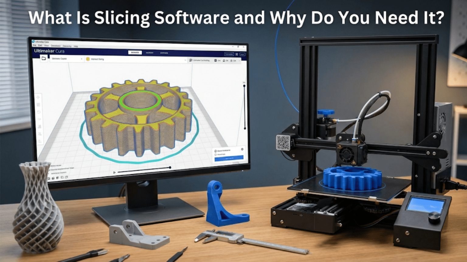
When newcomers first encounter three-dimensional printing, they often assume that sending a model to a printer works similarly to printing a document on paper—simply selecting “Print” from a menu and watching the output emerge. This assumption overlooks a critical intermediate step that makes the entire process possible: slicing software that transforms three-dimensional models into machine-readable instructions. Without this translation layer, printers would have no way to understand what objects should be created or how to construct them layer by layer.
Slicing software serves as the essential bridge between the digital design world and the physical manufacturing realm. It takes continuous three-dimensional surfaces described mathematically in CAD models and converts them into discrete layers with specific instructions for how material should be deposited, solidified, or fused at each height. This transformation involves complex computational geometry, path planning, and decision-making about countless parameters that affect how the final object emerges from the printer. Understanding what slicers do and why they matter helps users make informed decisions that dramatically affect print success, quality, and efficiency.
The name “slicer” comes from the fundamental operation these programs perform: conceptually slicing a three-dimensional model into thin horizontal cross-sections corresponding to the physical layers that will build during printing. However, modern slicing software does far more than just this geometric slicing operation. It generates support structures where needed, calculates efficient tool paths that minimize print time while maintaining quality, manages temperature changes and material switches, and optimizes countless aspects of the printing process. The slicer essentially serves as an intelligent manufacturing planner that must balance competing objectives and constraints to produce successful prints.
Different slicing programs offer varying capabilities, user interfaces, and philosophies about how much control users should have versus how much the software should handle automatically. Some slicers target beginners with simplified interfaces and automatic settings, while others provide professionals with granular control over hundreds of parameters. Understanding what capabilities matter for your specific needs helps select appropriate software from the many available options. Some slicers are free and open-source, others are commercial products, and still others are proprietary to specific printer manufacturers.
This comprehensive exploration of slicing software will examine what these programs actually do behind the scenes, why their role is essential to the 3D printing process, what key features distinguish different slicers, how to configure them effectively for good results, what advanced capabilities exist beyond basic slicing, and how to choose the right slicer for your equipment and applications. Whether you are just beginning with 3D printing or seeking to improve results through better understanding of your slicer, grasping these concepts provides foundation for consistent successful printing.
The Fundamental Functions of Slicing Software
Understanding what slicing software accomplishes requires examining the specific operations these programs perform to transform three-dimensional models into instructions that printers can execute. The complexity involved in this transformation exceeds what most users initially appreciate, with numerous interconnected processes happening behind the simple interface of loading a model and clicking “Slice.”
The geometric slicing operation that gives these programs their name involves mathematically intersecting the three-dimensional model with horizontal planes at regular intervals defined by the layer height setting. For a model with fifty millimeters of height printed at 0.2 millimeter layer height, the slicer calculates two hundred fifty intersections, determining what cross-sectional shape appears at each level. These cross-sections define the outline of solid material that must exist at each layer height to reconstruct the original three-dimensional form when stacked.
Path planning algorithms convert these cross-sectional outlines into specific tool paths that the print head or laser must follow to create each layer. For FDM printing, this involves calculating lines that trace around perimeters, fill internal areas with infill patterns, create solid top and bottom surfaces, and efficiently transition between different regions without wasting time or material. The path planning must consider factors like extrusion width, the need to connect lines continuously without excessive retractions, optimal sequencing to minimize travel moves, and strategies for maintaining consistent material flow.
Speed and acceleration management ensures movements stay within the mechanical limits of the printer while optimizing time without compromising quality. The slicer assigns different speeds to different features: slower speeds for outer perimeters where quality matters, faster speeds for infill where appearance doesn’t matter, and extremely slow speeds for first layers where adhesion is critical. Acceleration limits prevent the print head from trying to change speed or direction too quickly, which would cause missed steps, resonance, or quality defects. The slicer must calculate when to begin decelerating before corners and when to resume accelerating after turns.
Material flow calculations determine how much filament must be extruded at each point along the tool path to deposit the correct volume of material. The calculations account for the extrusion width, layer height, and printing speed to determine the linear velocity at which filament must be pushed into the hotend. If the print head moves faster, material must extrude faster proportionally. If the layer height increases, more material per unit length is needed. Getting these calculations wrong results in under-extrusion with gaps or over-extrusion with excess material causing defects.
Support generation analyzes the model geometry to identify overhanging features that cannot be printed without temporary support structures. The algorithms determine where supports are necessary based on overhang angle thresholds, generate support structures that reach from the build plate or existing solid layers up to the overhanging regions, and optimize support density and pattern to provide adequate structural support while minimizing material usage and ensuring supports can be removed cleanly after printing. Different support strategies like tree supports or organic supports attempt to minimize contact with the model surface.
Temperature management instructions embed commands into the output to control hotend and bed temperatures throughout the print. Initial heating to bring components to operating temperature, maintaining stable temperatures during printing, cooling for filament changes if printing with multiple materials, and final temperature reductions after completion all require explicit instructions that the slicer generates. Some prints benefit from temperature variations during the build, with initial layers printed hotter for adhesion and later layers cooler to reduce drooping.
Retraction instructions prevent stringing and oozing during travel moves where the print head moves between different areas without extruding. The slicer determines when travel moves occur, inserts commands to retract filament before the move by pulling it back into the hotend, executes the travel at high speed, then inserts commands to prime the nozzle by pushing material forward again before resuming extrusion. The retraction distance, speed, and any additional parameters like extra restart distance or retraction when layer changes all come from slicer settings.
Multi-part coordination manages the complexity when printing multiple separate objects simultaneously on the build plate. The slicer must sequence operations across all parts for each layer, determining an efficient order that minimizes travel distance while avoiding collisions between the print head and already-printed portions of other parts. For some part arrangements, certain sequencing orders become impossible because the print head physically cannot reach needed locations without striking existing geometry.
Why Slicing Software Is Essential
The necessity of slicing software for three-dimensional printing stems from fundamental incompatibilities between how three-dimensional models represent geometry and how printers physically build objects. Understanding these incompatibilities reveals why direct printing from CAD models is impossible without this intermediate translation step.
CAD models represent objects as continuous mathematical surfaces that exist in three-dimensional space without regard for how they might be manufactured. A curved surface might be defined by a mathematical equation that describes every point on an infinitely smooth surface. The model contains no information about layers, no concept of building direction, no consideration of how gravity affects material during construction, and no awareness of manufacturing constraints like maximum overhang angles or support requirements. This abstract mathematical representation works beautifully for design, analysis, and visualization but provides no path toward physical realization through additive manufacturing.
Printers operate in discrete physical reality where material must be deposited in specific patterns at specific locations in a specific sequence. An FDM printer’s nozzle follows finite paths in space, depositing material as it moves. The printer has no concept of continuous surfaces or mathematical curves; it only understands moving to specific coordinates and either extruding material or not during each movement. The instruction set consists of simple commands like “move to position X, Y, Z” and “extrude this much filament.” Bridging from continuous mathematical surfaces to discrete movement instructions requires the computational sophistication that slicing software provides.
The layer-by-layer construction paradigm of additive manufacturing requires decomposing three-dimensional geometry into sequences of two-dimensional cross-sections. This decomposition is not trivial because it must handle complex cases like surfaces at shallow angles to horizontal, overhangs that extend beyond lower layers, internal cavities, and countless geometric edge cases. The algorithms that perform this decomposition reliably across arbitrary geometries represent substantial computer science achievements, using computational geometry techniques to ensure correct results even for challenging shapes.
Manufacturing constraints specific to additive processes must be addressed during the translation from model to instructions. The need for support structures to hold up overhangs, the minimum feature sizes that can be reliably produced at given layer heights, the thermal considerations affecting how quickly material can be deposited without drooping, and the mechanical limits of how quickly the printer can move all require intelligent decision-making that accounts for both the geometry being produced and the specific printer’s capabilities. Slicing software embeds this manufacturing knowledge and applies it automatically.
Optimization opportunities exist during the translation from model to instructions that dramatically affect print time, material usage, and quality. Determining efficient travel paths that minimize air moves, choosing infill patterns that provide required strength with minimum material, sequencing operations to avoid unnecessary retractions, and identifying where slower speeds improve quality versus where faster speeds are acceptable all require analysis that slicing software performs. Without this optimization, prints would take far longer and use more material while potentially showing worse quality than optimized approaches achieve.
Parameter management across the hundreds of settings that affect printing would be completely impractical without software to organize and apply them. Print speed, layer height, temperature, retraction distance, infill density, support generation rules, cooling fan speeds, acceleration limits, and dozens of other parameters must be specified and applied correctly throughout the print. Slicing software packages these parameters into manageable profiles that apply sensible combinations while allowing users to adjust specific values when needed.
Hardware abstraction allows the same model to print on different printers without requiring users to understand the low-level details of each machine’s control system. The slicer generates G-code or other machine instructions appropriate for the specific printer, handling differences in coordinate systems, command syntax, or hardware capabilities. This abstraction means users can focus on what they want to print rather than how their specific printer’s firmware interprets commands.
Key Features That Distinguish Different Slicers
The market for slicing software includes numerous options ranging from simple free programs to sophisticated commercial tools, each with different feature sets, user interfaces, and target audiences. Understanding what features matter helps users select appropriate software for their needs and evaluate whether upgrading to more capable slicers would provide value.
The user interface philosophy varies dramatically between slicers targeting beginners versus professionals. Beginner-focused slicers hide complexity behind simplified interfaces with limited options and heavy reliance on automatic settings. These tools make getting started easy but may frustrate users as they gain experience and want more control. Professional slicers expose hundreds of settings organized in detailed menus, providing complete control at the cost of steeper learning curves. The best interface for you depends on your experience level and how much control you need versus want the software to decide automatically.
Support generation algorithms represent one area where slicers differ substantially. Basic support generation creates rectilinear columns or wall-like structures that support overhangs but use substantial material and leave surface marks. Advanced algorithms generate tree supports that branch organically to reach overhangs with minimal contact, organic supports that follow natural-looking forms, or customizable supports that allow manual placement and configuration. The quality of support algorithms affects both print success and post-processing time.
Print time estimation accuracy varies between slicers depending on how thoroughly they model the actual printing process. Simple slicers might estimate time by dividing total extrusion amount by average print speed, ignoring acceleration, retraction, and other factors that add time. Sophisticated slicers simulate the entire print including all movements, speed changes, and delays to provide estimates that closely match actual print times. Accurate estimates enable better planning and help evaluate whether settings changes meaningfully reduce print time.
Profile management systems help users organize the many settings combinations for different materials, qualities, and printers. Good profile systems include extensive libraries of pre-configured profiles for common scenarios, allow saving custom profiles, support importing and sharing profiles with other users, and make it easy to switch between profiles when printing different materials or at different quality levels. Poor profile management forces manually reconfiguring settings repeatedly or remembering which values work for specific combinations.
Visualization and preview capabilities allow examining the planned print before committing to it. Layer-by-layer preview showing exactly how each layer will print helps catch problems before wasting time and material. Color-coding by feature type distinguishes perimeters from infill from supports. Speed visualization shows where the printer will slow down or speed up. Travel move visualization reveals unnecessary air moves that waste time. The quality of these preview features affects how easily users can verify settings produce intended results.
Advanced path planning options provide control over how the slicer generates tool paths. Settings for seam placement determine where perimeter loops start and stop, affecting where visible seam lines appear. Ironing modes pass the nozzle back over top surfaces to smooth them. Monotonic top layers ensure infill lines go consistently in one direction for better surface appearance. Arc fitting converts many short linear segments into smooth arc movements. These advanced options help experienced users optimize prints beyond what default settings achieve.
Custom support painting and geometry editing allow manual control over features the slicer generates. Support painting lets users click specific areas that should have supports or should not have supports, overriding automatic generation. Height range modifiers allow different settings at different Z heights within a single print. Per-model settings enable printing multiple objects with different parameters in a single build. These customization features help address specific challenges that automatic settings cannot handle optimally.
Multi-material support determines whether the slicer can handle printers with multiple extruders or automatic material changers. Mapping different model volumes to different materials, generating appropriate wipe towers or purge objects for clean material transitions, and sequencing extruder switches efficiently all require specific support in the slicer. Multi-material capabilities vary from non-existent in simple slicers to sophisticated in professional tools designed for multi-material printing.
Configuring Slicers for Good Results
Successfully using slicing software requires understanding which settings matter most and how to configure them for the specific combination of printer, material, and quality requirements. While hundreds of settings exist in professional slicers, a relatively small subset accounts for most of the impact on print success and quality.
Layer height represents the single most influential setting affecting both print quality and time. Thinner layers create smoother surfaces with less visible layer lines but increase print time proportionally. Thicker layers print faster but show more obvious layer lines. The choice depends on whether the part will be visible, whether surface smoothness matters functionally, and how much time is available. Common values range from 0.1 millimeters for fine details to 0.3 millimeters for rapid functional prototypes. The layer height should typically be twenty-five to seventy-five percent of the nozzle diameter, with values outside this range risking quality issues.
Print speed balances quality against time, with slower speeds generally improving quality at the cost of longer prints. Outer perimeter speeds most directly affect surface quality, with twenty to forty millimeters per second producing good results for many materials. Infill can print faster since it does not affect appearance, perhaps sixty to one hundred millimeters per second. First layer speeds should be quite slow, twenty to thirty millimeters per second, for reliable adhesion. Finding optimal speeds requires experimentation with specific printer and material combinations.
Temperature settings profoundly affect print quality and reliability. Hotend temperature that is too low causes under-extrusion and poor layer adhesion. Temperature that is too high creates excessive stringing and drooping overhangs. The optimal temperature varies by material and color, with manufacturer recommendations providing starting points that require refinement through testing. Bed temperature affects first layer adhesion and warping, with higher temperatures generally improving adhesion at the cost of potentially making part removal more difficult.
Retraction settings control stringing and oozing during travel moves. Retraction distance determines how far filament pulls back, typically one to six millimeters depending on whether the extruder uses direct drive or Bowden configuration. Retraction speed affects how quickly the filament pulls back and pushes forward again. Finding optimal retraction settings requires test prints specifically designed to reveal stringing, then adjusting values to minimize strings without causing other issues like under-extrusion after retractions.
Wall thickness and top/bottom layer counts determine part strength and whether internal infill remains visible through surfaces. At least two to three perimeter walls provide reasonable strength, with more walls increasing strength at the cost of print time. Top and bottom surfaces need enough solid layers that infill does not show through, typically three to five layers depending on layer height and infill density. Transparent or translucent materials may require many more top layers to prevent infill from being visible.
Infill density and pattern affect strength, weight, and print time for parts that are not printed solid. Fifteen to thirty percent infill provides reasonable strength for many applications while saving substantial material and time compared to solid parts. Higher infill increases strength and rigidity. Patterns like grid, honeycomb, or gyroid provide different structural properties. Some patterns save time by requiring fewer tool path changes while others provide better strength for specific loading conditions.
Support generation settings determine when supports generate and how they connect to the model. Overhang angle thresholds, typically forty to sixty degrees from horizontal, control what features get support. Support density affects structural strength and ease of removal. Interface layers between supports and model reduce surface marking but may make supports harder to remove. Support patterns like zigzag, grid, or tree affect material usage and removal difficulty.
Adhesion helpers like brims, rafts, and skirts improve first layer reliability. Skirts prime the nozzle and verify bed leveling without touching the part. Brims extend from the part’s first layer, increasing adhered surface area to prevent warping. Rafts create separate base structures beneath parts, maximizing adhesion at the cost of material and potential bottom surface quality. Choosing appropriate adhesion strategies depends on material warping tendency and part geometry.
Advanced Capabilities Beyond Basic Slicing
Modern slicing software has evolved beyond simple model-to-G-code conversion to include sophisticated features that address specific challenges, enable advanced applications, and provide capabilities that professional users demand. Understanding these advanced features helps users recognize when upgrading to more capable slicers provides value.
Variable layer height allows automatically adjusting layer thickness throughout a print based on surface geometry. Flat or gradually curving surfaces print with thicker layers for speed while detailed areas use thinner layers for quality. This provides a compromise between fast printing and good detail that beats uniform layer height for parts with varying complexity. The slicer automatically analyzes geometry to determine where different layer heights make sense, though users can manually override the automatic decisions.
Sequential printing builds complete parts one at a time rather than interleaving layers across multiple parts. This prevents the visible layer lines that can occur when switching between parts at each layer, reduces oozing from excessive travel moves, and allows printing tall thin parts that would be vulnerable to print head collisions if other parts were being built simultaneously. The technique requires specific printer geometry with enough clearance for the print head to reach all locations without striking completed parts.
Firmware retraction and linear advance represent printer-side features that slicers can enable through appropriate G-code commands. Firmware retraction moves retraction logic into the printer’s firmware rather than specifying explicit retraction moves in G-code, potentially simplifying G-code files and allowing firmware-level optimization. Linear advance adjusts material flow dynamically during acceleration and deceleration to prevent over-extrusion at corners and under-extrusion after corners, improving dimensional accuracy and reducing artifacts.
Non-planar slicing breaks the traditional assumption that layers must be flat horizontal planes. Curved layer paths that follow surface contours can reduce or eliminate layer lines on angled surfaces, create stronger parts by aligning layers with stress patterns, or enable completely new construction strategies. This advanced technique requires specific printer configurations and firmware support but represents a frontier in additive manufacturing research that some experimental slicers support.
Custom G-code scripting allows inserting arbitrary G-code commands at specific points during prints. Users might pause for manual steps like inserting threaded inserts, change temperatures mid-print for surface appearance effects, trigger camera shots for time-lapse photography, or implement any other operations the printer’s firmware supports. This scripting capability extends what slicing software can orchestrate beyond the built-in features any slicer developers anticipated.
Modifiers and per-region settings enable different print parameters for specific model regions within a single print. A part might use high infill for a stressed area but low infill elsewhere to save time. External surfaces might use ironing for smoothness while internal surfaces use faster default settings. Different materials might be assigned to different volumes in multi-material setups. These region-specific controls enable optimization impossible with uniform settings across entire models.
Simulation and analysis features help predict print outcomes before committing to physical printing. Thermal simulation might predict where warping is likely to occur. Structural analysis could identify weak areas that need reinforcement. Build time analysis helps evaluate how settings changes affect duration. These simulation capabilities remain limited in current slicers but represent directions for future development that would help users optimize prints before rather than after manufacturing.
Cloud-based slicing and remote print management enable preparing prints on any device and monitoring printers remotely. Uploading models to cloud services, slicing them on powerful servers, and sending results to networked printers supports workflows where the computer used for design differs from the computer controlling the printer. Mobile apps allow checking print progress, receiving notifications about completion or problems, and even adjusting settings remotely. These connected capabilities suit print farms or situations where constant physical presence near printers is impractical.
Choosing the Right Slicer for Your Needs
With numerous slicing options available, selecting appropriate software requires evaluating your specific requirements against what different slicers offer. The “best” slicer depends entirely on your equipment, applications, experience level, and priorities.
Printer compatibility represents the most basic requirement, as slicers must support your specific printer or at least allow custom configuration for printers they do not explicitly list. Proprietary printer manufacturers may bundle specific slicers that integrate tightly with their equipment, potentially offering features or automatic configurations not available in generic slicers. However, these proprietary slicers may limit flexibility or lock users into specific ecosystems. Generic slicers like Cura or PrusaSlicer support vast ranges of printers through custom configuration, providing flexibility at the cost of potentially requiring manual setup.
Experience level should influence slicer selection, as tools designed for professionals may overwhelm beginners while tools targeting beginners may frustrate experienced users seeking more control. Starting with beginner-friendly slicers makes sense for newcomers who need to achieve basic results before understanding why advanced features matter. As skills develop, upgrading to more capable slicers or exploring advanced features in slicers that serve both beginners and professionals allows growth without switching software entirely.
Material requirements affect whether certain slicers are necessary. Single-material FDM printing works with essentially any slicer, but multi-material printing, soluble support materials, or specialty filaments might require specific slicer support. Resin printing requires slicers that understand resin-specific parameters and output formats appropriate for SLA or DLP printers. Understanding what materials you plan to use helps narrow slicer choices to those supporting those materials effectively.
Cost considerations matter since slicing software ranges from free open-source tools to commercial products with substantial license fees. Many excellent free slicers exist, including Cura, PrusaSlicer, and Slic3r, that provide capabilities adequate for most users. Commercial slicers like Simplify3D charge license fees but claim superior algorithms, better support, and additional features that professionals might value. Evaluating whether paid slicers provide sufficient benefits to justify their costs requires trying both free and paid options for comparison.
Feature requirements specific to your applications help identify which slicers provide needed capabilities. If you frequently print complex parts requiring sophisticated supports, slicers with advanced support algorithms become important. If you optimize parts through topology optimization requiring variable settings across regions, per-region modifiers become essential. If you run print farms, remote management capabilities matter. Listing your actual requirements focuses evaluation on slicers that deliver needed functionality rather than being distracted by features you will never use.
Community and support resources affect the learning curve and troubleshooting experience. Popular slicers benefit from extensive online communities, tutorial videos, forums where experienced users help newcomers, and collections of community-created profiles for specific materials and printers. Less popular slicers may offer excellent software but lack these community resources, making learning and troubleshooting more challenging. Evaluating community size and support availability helps predict whether you will find help when encountering problems.
Update frequency and development velocity indicate whether slicers will improve over time or stagnate. Active development brings bug fixes, new features, support for new printers and materials, and performance improvements. Slicers that have not been updated in years may work adequately for current needs but will not benefit from innovations or adapt to new technologies. Checking release histories and developer activity helps evaluate whether slicers represent ongoing investments versus abandoned projects.
Conclusion
Slicing software performs the essential function of translating three-dimensional models into machine instructions that printers can execute, making it indispensable to the 3D printing workflow. The geometric slicing that gives these programs their name represents just one aspect of sophisticated processes including path planning, support generation, speed optimization, material flow calculation, and countless other operations that determine whether prints succeed and how well results match expectations.
Understanding what slicers do and why they matter empowers users to make informed configuration decisions rather than blindly accepting default settings or randomly adjusting parameters hoping for improvement. The layer height, speed, temperature, retraction, and support settings that slicers expose directly control print characteristics, with appropriate configuration enabling results that poor settings cannot achieve regardless of hardware quality. Taking time to understand these parameters and how they interact pays dividends in print success rates and quality.
Different slicers offer varying capabilities, interfaces, and philosophies about how much control users should have versus how much the software should automate. Beginners benefit from simplified slicers that minimize complexity, while professionals need sophisticated tools providing granular control. The right choice depends on your specific needs, equipment, and experience level, with many excellent free options available alongside commercial alternatives that may provide additional value for specific professional applications.
The slicing software you choose and how effectively you configure it may ultimately affect print results more than differences in printer hardware within reasonable quality ranges. An experienced user with well-configured slicing software and entry-level printer hardware often achieves better results than a novice with expensive equipment but poor software configuration. This reality emphasizes the importance of investing time in understanding and mastering slicing software as a crucial component of successful 3D printing rather than viewing it as a transparent tool that requires no attention.
As the bridge between digital design and physical manufacturing, slicing software enables the geometric freedom, customization capabilities, and democratization of production that make additive manufacturing transformative. Understanding this essential tool allows leveraging 3D printing’s full potential rather than being limited by lack of knowledge about the software layer that makes everything possible.