Starting with Arduino can be both exciting and slightly intimidating, especially if you’re new to electronics and programming. Fortunately, Arduino is designed to be beginner-friendly, and one of the simplest and most iconic projects to start with is blinking an LED. This project introduces you to the basics of coding, wiring, and using the Arduino board, laying the foundation for more complex and creative projects in the future.
The “Blink” project is often the first Arduino project for beginners because it teaches fundamental concepts such as digital output, pin control, and timing. By making an LED blink, you’ll learn how to control electronic components with code, and you’ll get a hands-on introduction to working with Arduino’s Integrated Development Environment (IDE).
In this guide, we’ll walk you through the entire process of building your first Arduino project. We’ll cover the essential components you need, how to set up the circuit, writing and uploading your first code (called a “sketch”), and experimenting with different variations to deepen your understanding of Arduino basics.
What You’ll Need?
Before you get started, ensure you have the following components and tools ready:
- Arduino Board: For this project, we’ll be using the Arduino Uno, one of the most popular and beginner-friendly boards. However, you can use any Arduino-compatible board, such as the Arduino Nano or Mega.
- LED: Light Emitting Diode, used as an indicator in this project. LEDs have two legs; the longer leg is the anode (positive) and the shorter leg is the cathode (negative).
- 220-ohm Resistor: Resistors limit the current flowing through the LED, preventing it from burning out. A 220-ohm resistor is ideal for this simple circuit.
- Breadboard: A breadboard is used to build your circuit without soldering. It’s perfect for prototyping and experimenting.
- Jumper Wires: These are used to connect the components on the breadboard and link them to the Arduino.
- USB Cable: Used to connect the Arduino to your computer for programming and power.
- Arduino IDE: Ensure that the Arduino IDE is installed on your computer. If you haven’t installed it yet, you can download it from www.arduino.cc.
Setting Up the Circuit
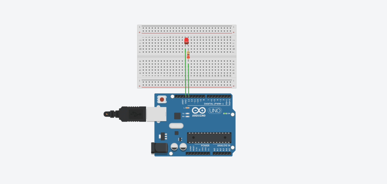
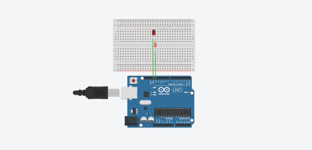
The circuit for this project is simple and straightforward. You will connect an LED to the Arduino board through a resistor, allowing you to control the LED with code.
Step-by-Step Circuit Setup:
- Place the LED on the Breadboard: Insert the LED into the breadboard. Make sure the longer leg (anode) is connected to the breadboard row that you’ll connect to the Arduino digital pin, and the shorter leg (cathode) is connected to the row that will be grounded.
- Connect the Resistor: Connect a 220-ohm resistor between the cathode of the LED and the ground (GND) rail on the breadboard. This resistor will limit the current, protecting the LED.
- Wire the Anode to the Arduino: Use a jumper wire to connect the row with the LED’s anode to digital pin 13 on the Arduino. Pin 13 is often used for the blink example because it’s directly linked to an onboard LED on many Arduino boards, allowing you to test without an external LED if desired.
- Connect the Ground: Use another jumper wire to connect the ground (GND) rail of the breadboard to one of the GND pins on the Arduino.
- Connect the Arduino to Your Computer: Use the USB cable to connect the Arduino to your computer. This will power the Arduino and allow you to upload your code.
Here’s a simple diagram of the circuit:
- Arduino Pin 13 -> LED Anode (long leg)
- LED Cathode (short leg) -> 220-ohm resistor -> Ground (GND)
This setup ensures that when the Arduino outputs a signal to Pin 13, the LED will receive current and light up.
Writing Your First Sketch
Now that your circuit is set up, it’s time to write the code that will make the LED blink. In Arduino terminology, a program is called a “sketch.” This sketch will control the LED by turning it on and off in a loop.
Step-by-Step Guide to Writing the Blink Sketch:
1. Open the Arduino IDE: Launch the Arduino IDE on your computer. If it’s your first time using the IDE, take a moment to familiarize yourself with the layout, including the code editor, toolbar, and message area.
2. Select Your Board and Port:
- Go to
Tools > Boardand select your Arduino model (e.g., Arduino Uno). - Go to
Tools > Portand select the COM port associated with your Arduino board.
3. Write the Code: Type the following code into the editor. This sketch will turn the LED on for one second and then off for one second, repeating indefinitely.
// Define the pin number for the LED
const int ledPin = 13;  // Pin 13 has an LED connected on most Arduino boards

// The setup function runs once when you press reset or power the board
void setup() {
  pinMode(ledPin, OUTPUT);  // Initialize the digital pin as an output
}

// The loop function runs over and over again forever
void loop() {
  digitalWrite(ledPin, HIGH);  // Turn the LED on (HIGH is the voltage level)
  delay(1000);                 // Wait for one second
  digitalWrite(ledPin, LOW);   // Turn the LED off by making the voltage LOW
  delay(1000);                 // Wait for one second
}4. Upload the Code to Your Arduino: Click the “Upload” button (right-pointing arrow) in the top-left corner of the Arduino IDE. The IDE will compile your code, and if there are no errors, it will upload the sketch to your Arduino board.
5. Watch the LED Blink: If everything is set up correctly, the LED should start blinking on and off at one-second intervals. Congratulations, you’ve successfully completed your first Arduino project!
Understanding the Code
Let’s break down the code to understand what each part does:
const int ledPin = 13;: This line defines a constant variable calledledPinand assigns it the value of 13, which corresponds to digital pin 13 on the Arduino.void setup(): This function runs once when the Arduino is powered on or reset. It is used to initialize settings, such as setting up the pin modes. In this sketch,pinMode(ledPin, OUTPUT);tells the Arduino that Pin 13 will be used as an output.void loop(): This function runs continuously aftersetup(). In this case, it contains the code to turn the LED on and off repeatedly.digitalWrite(ledPin, HIGH);: This command sets the specified pin (Pin 13) to a HIGH state, which turns the LED on.delay(1000);: Thedelay()function pauses the program for the specified time in milliseconds (1000 milliseconds = 1 second).digitalWrite(ledPin, LOW);: This command sets the specified pin to a LOW state, turning the LED off.
The combination of these commands makes the LED blink on and off in a repeating loop, demonstrating how you can control components with code.
Experimenting with the Blink Sketch
To deepen your understanding of Arduino, try modifying the Blink sketch and observing the effects:
- Change the Blink Rate: Modify the delay times to make the LED blink faster or slower. For example, change
delay(1000);todelay(500);to make the LED blink twice as fast. - Use Different Pins: Move the LED connection from Pin 13 to another digital pin, such as Pin 7, and update the code (
const int ledPin = 7;). This will help you learn how to control other pins. - Add Multiple LEDs: Expand the project by adding more LEDs and controlling them individually. Assign each LED to a different pin, define each pin as an output in
setup(), and modify theloop()to create different blinking patterns.
By experimenting with the code and circuit, you’ll gain valuable hands-on experience and learn how to think creatively about electronics and programming.
Exploring Variations and Expanding Your First Arduino Project
Experimenting with Different LED Patterns
Once you’ve mastered the basic LED blink, you can start exploring different patterns and sequences to make your project more interesting. By modifying the code, you can control multiple LEDs, create complex sequences, and even simulate effects like traffic lights or running lights. Here are a few variations to try that will deepen your understanding of how Arduino controls digital outputs.
1. Blinking Multiple LEDs Sequentially:
In this variation, you will add more LEDs and make them blink one after the other in a sequence. This is a great way to learn about controlling multiple pins and managing code for more complex behavior.
Components Needed:
- 3 x LEDs (any color)
- 3 x 220-ohm resistors
- Additional jumper wires
Circuit Setup:
- Place three LEDs on the breadboard with their anodes connected to digital pins 8, 9, and 10 on the Arduino, respectively.
- Connect each LED’s cathode to a 220-ohm resistor, and then connect the resistors to the ground rail on the breadboard.
- Connect the ground rail to one of the GND pins on the Arduino.
Code for Sequential Blinking: Here’s the updated code to make the LEDs blink in sequence:
// Define the pin numbers for each LED
const int ledPin1 = 8;  // First LED
const int ledPin2 = 9;  // Second LED
const int ledPin3 = 10; // Third LED

void setup() {
  // Initialize the digital pins as outputs
  pinMode(ledPin1, OUTPUT);
  pinMode(ledPin2, OUTPUT);
  pinMode(ledPin3, OUTPUT);
}

void loop() {
  // Turn on the first LED, then off
  digitalWrite(ledPin1, HIGH);
  delay(500);
  digitalWrite(ledPin1, LOW);

  // Turn on the second LED, then off
  digitalWrite(ledPin2, HIGH);
  delay(500);
  digitalWrite(ledPin2, LOW);

  // Turn on the third LED, then off
  digitalWrite(ledPin3, HIGH);
  delay(500);
  digitalWrite(ledPin3, LOW);
}What This Code Does:
- The
pinMode()function initializes each pin as an output. - In the
loop(), each LED is turned on and off sequentially with a half-second delay, creating a chasing light effect.
Try changing the delay times or adding more LEDs to extend the sequence. You can also modify the code to make the LEDs light up in different patterns, such as blinking simultaneously or in reverse order.
2. Traffic Light Simulation:
Simulating a traffic light is a fun way to learn about controlling multiple LEDs with specific timing sequences. This project will use red, yellow, and green LEDs to mimic the operation of a traffic signal.
Components Needed:
- 1 x Red LED
- 1 x Yellow LED
- 1 x Green LED
- 3 x 220-ohm resistors
Circuit Setup:
- Place the red, yellow, and green LEDs on the breadboard, connecting their anodes to pins 8, 9, and 10, respectively.
- Connect each LED’s cathode to ground through a 220-ohm resistor.
Code for Traffic Light Simulation: Here’s the code to create a simple traffic light pattern:
// Define the pin numbers for each LED
const int ledPin1 = 8;  // First LED
const int ledPin2 = 9;  // Second LED
const int ledPin3 = 10; // Third LED

void setup() {
  // Initialize the digital pins as outputs
  pinMode(ledPin1, OUTPUT);
  pinMode(ledPin2, OUTPUT);
  pinMode(ledPin3, OUTPUT);
}

void loop() {
  // Turn on the first LED, then off
  digitalWrite(ledPin1, HIGH);
  delay(500);
  digitalWrite(ledPin1, LOW);

  // Turn on the second LED, then off
  digitalWrite(ledPin2, HIGH);
  delay(500);
  digitalWrite(ledPin2, LOW);

  // Turn on the third LED, then off
  digitalWrite(ledPin3, HIGH);
  delay(500);
  digitalWrite(ledPin3, LOW);
}
What This Code Does:
- The green LED turns on for 5 seconds, simulating the “go” signal.
- The yellow LED lights up for 2 seconds, representing the “caution” phase.
- The red LED turns on for 5 seconds, indicating “stop.”
You can adjust the delay times to simulate different traffic light timing or add additional LEDs for more complex light patterns.
3. Fading an LED with PWM:
In addition to simply turning an LED on and off, Arduino can use Pulse Width Modulation (PWM) to control the brightness of an LED, creating a fading effect. PWM is a technique that quickly turns a pin on and off, simulating varying voltage levels.
Components Needed:
- 1 x LED
- 1 x 220-ohm resistor
Circuit Setup:
- Connect the anode of the LED to PWM-capable pin 9 on the Arduino (pins labeled with a tilde, such as ~9).
- Connect the cathode of the LED to ground through a 220-ohm resistor.
Code for Fading LED: Here’s the code to make an LED fade in and out smoothly:
const int ledPin = 9; // Pin connected to the LED

void setup() {
  pinMode(ledPin, OUTPUT); // Set pin as an output
}

void loop() {
  // Fade the LED in
  for (int brightness = 0; brightness <= 255; brightness++) {
    analogWrite(ledPin, brightness); // Set the brightness level
    delay(10); // Wait for 10 milliseconds
  }

  // Fade the LED out
  for (int brightness = 255; brightness >= 0; brightness--) {
    analogWrite(ledPin, brightness);
    delay(10);
  }
}What This Code Does:
- The
analogWrite()function sets the LED’s brightness by outputting a PWM signal. - Two
forloops gradually increase and decrease the brightness value, creating a smooth fade in and fade out effect.
Experiment with different delay times or brightness ranges to see how they affect the fading speed and intensity.
Debugging Common Issues in Your Arduino Projects
As you experiment with your Arduino projects, you might encounter some common issues. Here are troubleshooting tips to help you resolve them:
1. The LED Doesn’t Light Up:
- Check Connections: Ensure that the LED, resistors, and wires are connected correctly and firmly on the breadboard.
- Verify Pin Numbers: Double-check that the pin numbers in your code match the physical connections on the board.
- Test the LED and Resistor: Swap the LED and resistor with new ones to rule out defective components.
2. Upload Errors:
- Board Not Detected: Make sure your Arduino is connected properly and that the correct board and port are selected in the IDE.
- Reset the Board: Press the reset button on your Arduino and try uploading the sketch again.
- Check USB Cable: A faulty USB cable can cause upload errors; try using a different cable.
3. Sketch Uploads but Behavior is Unexpected:
- Code Errors: Review the code for typos or logical errors. Use the Serial Monitor (
Tools > Serial Monitor) to add debug messages that can help trace the code execution. - Incorrect Pin Modes: Ensure that pins are configured correctly in the
setup()function, as incorrect modes can cause unexpected results.
4. LEDs Flicker or Blink Erratically:
- Power Supply Issues: Ensure that your Arduino is receiving stable power. If you are powering the Arduino from a computer, try using a different USB port or an external power source.
- Long Jumper Wires: Long or loose connections can introduce noise or unstable signals. Use shorter jumper wires and ensure all connections are secure.
Expanding Your Skills Beyond Blinking LEDs
As you gain confidence with Arduino, you can build on the skills learned from the blink project to explore more complex and rewarding projects. Here are some ideas to consider:
- Build a Morse Code Transmitter: Expand the blink project into a Morse code transmitter by programming your Arduino to blink messages using the international Morse code standard.
- Control LEDs with Sensors: Combine LEDs with sensors like buttons, light sensors (LDRs), or temperature sensors to create interactive light displays that respond to environmental changes.
- Explore RGB LEDs: Use RGB (Red, Green, Blue) LEDs to create a wide range of colors by mixing light intensities. This is a great introduction to working with color and PWM.
- Create Animations with LED Arrays: Set up multiple LEDs in a grid or matrix to create animations, text displays, or game interfaces like a simple version of Pong or Snake.
Arduino offers endless possibilities for creative expression, problem-solving, and learning. By experimenting with these foundational skills, you’ll build the confidence and knowledge needed to tackle increasingly ambitious projects, opening up a world of possibilities in electronics and coding.
Expanding Your First Arduino Project: Advanced LED Control and Beyond
Adding Sensors and Inputs to Your LED Project
After mastering the basics of blinking and fading LEDs, the next step is to make your Arduino project interactive by adding sensors and inputs. By incorporating buttons, potentiometers, or light sensors, you can control the behavior of LEDs dynamically, allowing for more complex and engaging projects. Here’s how you can extend your LED project with some common inputs.
1. Controlling an LED with a Button:
Adding a pushbutton to your Arduino project allows you to control the LED manually. This is a simple yet powerful way to learn about digital inputs and how Arduino reads user interaction.
Components Needed:
- 1 x Pushbutton
- 1 x 10k-ohm resistor (for the pull-down circuit)
Circuit Setup:
- Place the pushbutton on the breadboard. Connect one side of the button to 5V on the Arduino.
- Connect the other side of the button to digital pin 7 on the Arduino.
- Use a 10k-ohm resistor to connect pin 7 to the ground (GND). This pull-down resistor ensures that the pin reads LOW when the button is not pressed.
Code for Button-Controlled LED:
const int ledPin = 13;   // LED connected to digital pin 13
const int buttonPin = 7; // Button connected to digital pin 7
int buttonState = 0;     // Variable to store the button state

void setup() {
  pinMode(ledPin, OUTPUT);  // Set LED pin as an output
  pinMode(buttonPin, INPUT); // Set button pin as an input
}

void loop() {
  // Read the state of the button
  buttonState = digitalRead(buttonPin);

  // If the button is pressed, turn on the LED
  if (buttonState == HIGH) {
    digitalWrite(ledPin, HIGH);
  } else {
    digitalWrite(ledPin, LOW);
  }
}What This Code Does:
- The
digitalRead()function checks if the button is pressed. - If the button is pressed (HIGH), the LED turns on; otherwise, it remains off.
Try modifying the code to toggle the LED state with each button press, adding another layer of interactivity.
2. Using a Potentiometer to Adjust LED Brightness:
A potentiometer is a variable resistor that can be used to adjust the brightness of an LED by controlling the PWM signal sent to the pin.
Components Needed:
- 1 x Potentiometer (10k-ohm)
Circuit Setup:
- Connect the left pin of the potentiometer to 5V and the right pin to GND.
- Connect the middle pin (wiper) of the potentiometer to analog pin A0 on the Arduino.
Code for Potentiometer-Controlled Brightness:
const int ledPin = 9;   // LED connected to PWM pin 9
const int potPin = A0;  // Potentiometer connected to analog pin A0
int potValue = 0;       // Variable to store the potentiometer value

void setup() {
  pinMode(ledPin, OUTPUT); // Set LED pin as an output
}

void loop() {
  // Read the potentiometer value (0 to 1023)
  potValue = analogRead(potPin);

  // Map the potentiometer value to a range of 0 to 255
  int brightness = map(potValue, 0, 1023, 0, 255);

  // Set the LED brightness using PWM
  analogWrite(ledPin, brightness);
}What This Code Does:
- The
analogRead()function reads the potentiometer’s position, which ranges from 0 to 1023. - The
map()function scales this value to a range suitable for PWM (0 to 255). - The
analogWrite()function adjusts the LED’s brightness according to the potentiometer’s position.
Experiment with different input devices, like photoresistors or temperature sensors, to further enhance the interactivity of your projects.
Building a Light-Sensitive LED System
Another exciting variation is to build a light-sensitive LED system using a Light Dependent Resistor (LDR). This setup allows the LED to react to the surrounding light levels, automatically turning on when it’s dark.
Components Needed:
- 1 x LDR (Light Dependent Resistor)
- 1 x 10k-ohm resistor
Circuit Setup:
- Connect one side of the LDR to 5V and the other side to analog pin A0.
- Connect a 10k-ohm resistor between analog pin A0 and GND to create a voltage divider circuit.
Code for Light-Sensitive LED:
const int ledPin = 13;   // LED connected to pin 13
const int ldrPin = A0;   // LDR connected to analog pin A0
int ldrValue = 0;        // Variable to store the LDR value

void setup() {
  pinMode(ledPin, OUTPUT); // Set LED pin as an output
  Serial.begin(9600);      // Start the serial monitor
}

void loop() {
  // Read the LDR value (0 to 1023)
  ldrValue = analogRead(ldrPin);

  // Print the LDR value to the Serial Monitor for debugging
  Serial.println(ldrValue);

  // Turn on the LED if it’s dark (value above 600)
  if (ldrValue > 600) {
    digitalWrite(ledPin, HIGH);
  } else {
    digitalWrite(ledPin, LOW);
  }

  delay(100); // Small delay to avoid excessive readings
}What This Code Does:
- The LDR measures the light level, and the analog value is read by the Arduino.
- If the reading is above a certain threshold (indicating darkness), the LED turns on.
- The
Serial.println()function helps monitor the LDR value for debugging.
You can adjust the threshold value based on your environment and use cases, allowing the system to respond appropriately to different lighting conditions.
Going Further: Expanding Beyond LEDs
The fundamental skills you’ve learned in these LED projects can be extended to control other components, making your Arduino journey limitless. Here are some advanced directions to explore:
- Controlling Motors: Replace LEDs with motors to build simple robots or moving mechanisms. For example, use a DC motor to spin a fan, or a servo motor to control movement precisely, such as in robotic arms or automated systems.
- Creating Sound Effects: Use a piezo buzzer instead of an LED to create sound effects or alarms. Combine the buzzer with sensors like buttons or distance sensors to make interactive sound-based projects.
- Building Displays: Replace LEDs with LCD displays to show text, numbers, or even graphics. You can create real-time displays for temperature, distance, or other sensor readings, enhancing the visual feedback of your projects.
- Wireless Communication: Add wireless modules like Bluetooth or Wi-Fi to control your LEDs remotely via a smartphone or web interface. This is a stepping stone into building more sophisticated IoT (Internet of Things) projects.
- Data Logging and Analysis: Instead of just turning LEDs on and off, use sensors to collect data, log it to an SD card, or send it to a computer for analysis. This could include monitoring environmental conditions, tracking system performance, or conducting scientific experiments.
Conclusion
Blinking an LED is more than just a simple starting project—it’s the gateway to understanding the core principles of electronics, coding, and the limitless possibilities of Arduino. Through this first project, you’ve learned how to control outputs, read inputs, and create interactive systems. As you continue to experiment, you’ll discover that Arduino offers endless opportunities to innovate, solve problems, and bring your ideas to life.
By building on this foundation, you can progress to more complex and rewarding projects, whether it’s creating smart home devices, developing robotics, or exploring the world of IoT. Remember, every great project starts with a single blink.
Keep exploring, keep experimenting, and most importantly, keep learning. With Arduino, you’re not just building circuits—you’re building the future.