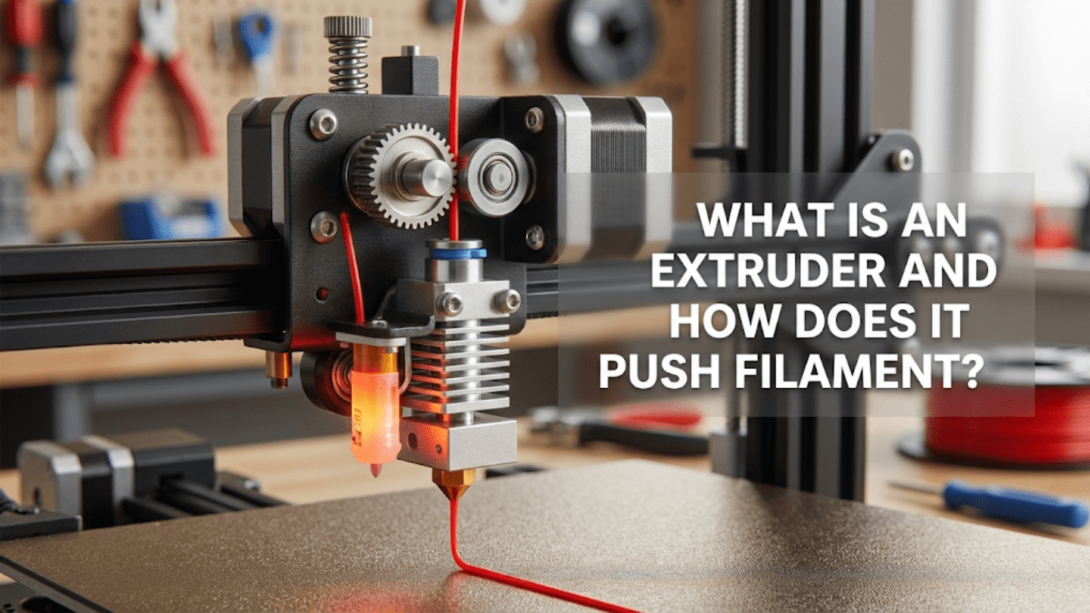
An extruder is the mechanical component in a 3D printer that grips filament with a motorized gear system and pushes it forward at precisely controlled rates into the hotend for melting and deposition. It consists of a stepper motor, drive gear(s) that bite into the filament, an idler or second gear that provides pressure, tension adjustment mechanisms, and a filament path that guides material from the spool through the extruder and onward to the hotend.
Introduction
Among all the components in a 3D printer, the extruder has arguably the most demanding job. It must grip a slippery plastic filament with enough force to push it through the considerable resistance of a molten melt zone and tiny nozzle opening, yet not grip so hard that it deforms or grinds through the filament. It must maintain consistent pressure for hours on end while starting, stopping, reversing, and accelerating thousands of times during a print. It needs to handle materials ranging from rock-hard polycarbonate to squishy flexible TPU, adjusting to their different physical properties seamlessly.
Despite this critical role, many beginners view the extruder as simply “the part that feeds plastic” without understanding the sophisticated engineering that makes consistent extrusion possible. When prints show under-extrusion, grinding noises emerge, or flexible filaments refuse to feed, the extruder often bears responsibility—yet many users don’t know how to diagnose or fix these issues because they don’t understand the mechanism.
In this comprehensive guide, we’ll examine exactly what an extruder is and how it accomplishes its vital function. You’ll learn about the different extruder types, understand the mechanical principles behind filament feeding, discover what makes some extruders better than others, and gain the knowledge needed to optimize your extruder’s performance or make informed upgrade decisions.
The Extruder’s Primary Function: Controlled Filament Feeding
At its most basic level, the extruder’s job is deceptively simple: push filament forward at exactly the rate needed to deposit the correct amount of molten plastic. However, achieving this “simple” task reliably requires solving several engineering challenges simultaneously.
Precision Volume Control
The extruder must deliver exact volumes of plastic. When your slicer calculates that a particular movement needs 0.05 cubic millimeters of material, the extruder must push exactly that amount of filament forward—no more, no less. Too much creates over-extrusion with blobby surfaces and dimensional inaccuracy. Too little produces under-extrusion with weak parts and gaps in the walls.
This precision requirement becomes even more demanding because the extruder doesn’t directly measure plastic volume. Instead, it measures the linear distance that filament travels. The firmware knows the filament diameter (typically 1.75mm or 2.85mm) and calculates how much linear filament movement produces the desired plastic volume. Any variation in actual filament diameter causes corresponding errors in the deposited volume.
The extruder motor typically moves in steps of 0.0125mm or finer, though microstepping can divide these into even smaller increments. This resolution allows extremely precise filament feeding—in theory. In practice, the extruder must overcome various sources of error including filament compression, mechanical flex, and the slippage that inevitably occurs when gripping smooth plastic.
Force Generation and Transmission
Pushing filament through a hotend requires substantial force. The molten plastic creates significant back-pressure as it’s forced through the increasingly restrictive path culminating in the tiny nozzle orifice. Smaller nozzles create more resistance. Higher print speeds demand higher flow rates, increasing resistance further. Some materials flow more easily than others—PLA flows relatively freely, while materials like polycarbonate exhibit much higher viscosity.
The extruder must generate enough force to overcome this resistance reliably. Standard stepper motors produce limited torque, so extruders use mechanical advantage through gearing to multiply the motor’s force. A 3:1 gear ratio means the extruder can apply three times more force than the motor produces directly, though at the cost of requiring three motor rotations to advance filament one effective rotation’s worth.
This force must be transmitted to the filament effectively. The drive gear bites into the relatively soft plastic with sharp teeth, creating a mechanical interlock. Too little gripping pressure and the filament slips without advancing—you’ll hear the motor turning while nothing extrudes. Too much pressure and the teeth grind through the filament, creating plastic dust and eventually grinding a flat spot that prevents any further feeding.
Responsiveness and Control
The extruder must respond instantly to commands. When the printer needs to stop extruding—when moving between features without printing, for example—the extruder must halt immediately. When retraction pulls filament backward to prevent oozing, the extruder must reverse quickly and precisely. When resuming extrusion, it must accelerate smoothly to the commanded flow rate without delay.
This responsiveness challenge becomes particularly acute in Bowden configurations where a long PTFE tube separates the extruder from the hotend. The tube’s springiness absorbs some of the extruder’s movement, creating lag between when the extruder motor moves and when filament actually feeds into the hotend. Direct drive configurations minimize this lag by mounting the extruder immediately above the hotend.
The extruder motor receives step and direction signals hundreds or thousands of times per second during active printing. It must accelerate, maintain speed, and decelerate smoothly while the mechanical system transmits this motion reliably to the filament. Any backlash, flex, or slop in the mechanical linkages introduces errors that compromise print quality.
Extruder Components and Mechanisms
Understanding how extruders work requires examining their constituent parts and how they interact:
The Stepper Motor
Every extruder uses a stepper motor to drive the mechanism. These motors move in discrete steps rather than continuous rotation, allowing precise position control without feedback sensors. The motor receives electrical pulses from the printer’s mainboard—each pulse commands one step of rotation.
Most extruders use NEMA 17 stepper motors, the same standard size used for axis movement. However, extruder motors face different requirements than axis motors. They need more torque to push filament through resistance but don’t need high rotational speed since filament feeding rates are relatively slow compared to axis movement speeds.
Standard NEMA 17 motors measure 42mm x 42mm at the mounting face, but they vary in length and consequently in torque output. Longer motors generally produce more torque—a 40mm long motor might produce 40 N·cm of holding torque, while a 48mm motor produces 48 N·cm or more. Higher torque helps when printing materials with high flow resistance or when using small nozzles.
Some extruders use “pancake” stepper motors—very short NEMA 17 motors only 20-25mm thick. These save weight for direct drive applications where the motor mounts on the moving carriage. However, they produce less torque than standard motors, so they typically require higher gear ratios to achieve adequate filament pushing force.
The motor shaft extends from one end, typically 5mm in diameter with a flat ground on one side to prevent rotation relative to set screws. The drive gear mounts on this shaft, sometimes directly or through additional gear reduction.
Drive Gear Systems
The drive gear transfers motor rotation to filament movement. Several design approaches exist:
Single-Gear (Hobbed Bolt) Design: The original and simplest approach uses a single gear with sharp teeth (called a “hobb”) that bites into the filament. An idler bearing presses the filament against the drive gear, trapping it between the toothed gear and smooth bearing. The motor rotates the drive gear, teeth bite into the filament, and the filament advances.
This design works adequately for rigid materials like PLA and ABS when properly tensioned. However, it has limitations. The contact area between filament and drive gear is relatively small—just one side of the filament contacts the toothed gear. High pressures concentrate at this contact point, which can grind through the filament if resistance becomes too great. The idler bearing provides pressure but doesn’t actively drive the filament.
Dual-Gear (BMG-Style) Design: Modern extruders increasingly use dual-gear designs where two toothed gears mesh together with the filament trapped between them. Both gears bite into the filament from opposite sides, distributing force more evenly and approximately doubling the contact area compared to single-gear designs.
Dual-gear extruders typically incorporate gear reduction as well. One common implementation uses a small motor-driven gear that meshes with a larger compound gear. This compound gear has two sections—a large gear driven by the motor’s pinion, and a smaller toothed section that engages the filament. The opposing filament gear meshes with both the filament and the drive gear.
This arrangement provides two benefits simultaneously: gear reduction that multiplies motor torque, and dual-sided filament gripping that reduces the chance of grinding and allows higher forces when needed. The typical 3:1 gear ratio means the motor rotates three times to advance filament a distance equivalent to one rotation of the filament gears.
Geared vs. Direct Drive Gearing: Don’t confuse “geared extruder” with “direct drive mounting.” The terms refer to different things:
- A geared extruder uses gear reduction between the motor and filament (like BMG-style extruders)
- A direct drive configuration mounts the extruder assembly directly on the hotend carriage (vs. Bowden remote mounting)
You can have geared direct drive extruders, non-geared direct drive extruders, geared Bowden extruders, or non-geared Bowden extruders—the concepts are independent.
Idler Mechanism and Tension Adjustment
The idler provides the opposing force that traps filament against the drive gear. This component must press firmly enough to prevent slipping without crushing the filament or creating excessive friction.
Simple bearing idlers use a smooth bearing that presses against the filament opposite the drive gear. A spring pushes the bearing toward the drive gear, with adjustable tension controlling the pressure. Turning a tension screw compresses the spring more (increasing pressure) or releases it (decreasing pressure).
Dual-gear idlers in BMG-style extruders use a second toothed gear instead of a smooth bearing. This idler gear rotates freely on its shaft but engages the filament with teeth identical to the drive gear. The meshing gears pull filament through with force applied from both sides.
Lever-based systems use lever mechanisms to convert spring compression into filament pressure. The leverage ratio affects how much force reaches the filament for a given spring compression. Some designs include quick-release levers that allow swinging the idler away without adjusting tension—convenient for loading filament.
Proper tension adjustment is crucial but often misunderstood:
Too loose: Filament slips when resistance increases. You’ll see under-extrusion, hear the motor ticking as it tries to push without gaining traction, and might notice ground filament dust around the extruder.
Too tight: Excessive pressure deforms the filament, creating an inconsistent diameter that causes flow variation. Very high pressure can grind completely through the filament, creating a smooth channel where teeth can’t engage. Flexible filaments especially suffer from over-tightening.
Just right: Filament advances smoothly without slipping. The drive gear teeth leave visible marks on the filament but don’t grind through it. You can hold the filament entering the extruder and feel firm but not extreme resistance if you try to prevent its movement.
Most extruders have some adjustment range, but finding optimal tension often requires trial and error. Start with moderate tension, print a test object, and adjust if you see symptoms of slipping (too loose) or grinding (too tight).
Filament Path and Guides
The path filament follows through the extruder affects feeding reliability. Poor design creates binding points where friction increases unnecessarily.
Entry guide: At the point where filament enters the extruder, a guide funnel or tube aligns it properly with the drive gear. Misaligned filament can cause feeding problems as it tries to enter at an odd angle.
Drive section alignment: The drive gear and idler must align precisely. If the gears are offset, filament gets pushed sideways as it passes through, creating friction and wear. Quality extruders use precision-machined parts that align correctly without adjustment.
Exit guide: After passing the drive gear, filament continues to either the hotend (direct drive) or the Bowden tube connection (Bowden systems). Smooth transitions prevent catching and binding.
Some extruders include filament sensors in the path. These detect whether filament is present and moving, allowing the printer to pause automatically if filament runs out or breaks during printing.
Bowden Connector
In Bowden configurations, the extruder connects to a PTFE tube that guides filament to the remotely located hotend. This connection uses pneumatic fittings—quick-connect couplers that grip the tube firmly while allowing easy removal when needed.
The tube must seat fully into the fitting to prevent gaps where filament could catch or buckle. The fitting includes a collet with teeth that bite into the tube’s exterior, an O-ring that seals, and a release collar that spreads the collet teeth to allow tube removal.
Quality fittings matter more than many realize. Cheap fittings can loosen over time, allowing the tube to slip backward. This creates gaps and feeding problems. Better fittings maintain secure grip through thousands of retractions and extrusions.
Bowden vs. Direct Drive: Configuration Comparison
The relationship between the extruder and hotend defines two fundamental configuration types, each with distinct advantages and limitations:
Bowden Extruder Configuration
Bowden systems mount the extruder motor and drive mechanism on the printer’s stationary frame, separated from the hotend. A PTFE tube guides filament from the extruder across the distance to the hotend, which mounts on the moving print head carriage.
Advantages:
Reduced moving mass: Keeping the heavy motor stationary means only the lightweight hotend moves during printing. Less mass to accelerate and decelerate allows faster printing speeds and reduces ringing artifacts caused by inertial forces.
Simpler carriage design: The moving carriage only carries the hotend, cooling fan, and probe if equipped. This simplicity reduces complexity and cost.
Lower frame stress: With less mass moving rapidly, the printer’s frame experiences less dynamic loading. This can improve print quality on printers without extremely rigid frames.
Better speed potential: The reduced moving mass allows aggressive acceleration settings that would cause problems with heavier direct drive systems.
Disadvantages:
Retraction challenges: The PTFE tube compresses slightly under the pressure of pushing filament. When retracting to prevent oozing, the extruder must pull filament back far enough to overcome this compression before filament actually moves at the hotend. This requires longer retraction distances (4-6mm or more) compared to direct drive (0.5-2mm).
Flexible filament problems: Soft materials like TPU tend to buckle inside the tube rather than advancing when the extruder pushes. The lack of complete constraint along the tube’s length allows the filament to bend and compress instead of transmitting force to the hotend.
Reduced precision: The tube’s springiness creates lag between extruder movement and actual filament delivery at the hotend. This affects fine control and makes pressure advance/linear advance algorithms less effective.
Tube friction: Filament sliding through the tube creates friction that the extruder must overcome. Longer tubes or tubes with bends increase this friction.
Tube maintenance: The PTFE tube degrades over time, especially at the hotend connection where heat affects it. The tube requires periodic replacement to maintain performance.
Direct Drive Extruder Configuration
Direct drive configurations mount the extruder motor and mechanism directly on the moving print head carriage, positioning it immediately above the hotend.
Advantages:
Excellent retraction: With the extruder right at the hotend, retraction becomes extremely responsive. Very short retraction distances (0.5-2mm) work effectively because there’s no tube compliance to overcome.
Flexible filament capability: The short, fully constrained path from drive gear to hotend allows reliable printing of soft materials. TPU, TPE, and other flexible filaments that fail completely in Bowden systems work well in direct drive.
Precise control: Immediate response to extruder commands allows better fine control over extrusion. Pressure advance/linear advance algorithms work more effectively.
No tube maintenance: Eliminating the Bowden tube removes one maintenance item and potential failure point.
Better for detailed prints: The precise control benefits fine details, thin walls, and features requiring exact extrusion control.
Disadvantages:
Increased moving mass: The motor adds significant weight to the moving carriage. NEMA 17 motors typically weigh 200-300 grams, plus the extruder mechanism itself adds more.
Slower speed potential: The additional mass requires lower acceleration settings to avoid ringing and other artifacts. Print speeds may need reduction compared to Bowden equivalents.
More complex carriage: Mounting and wiring the motor on the moving carriage increases mechanical complexity.
Higher frame demands: The increased dynamic loads require more rigid frames to maintain quality. Printers with flexible frames may see reduced performance.
Cable management challenges: The motor cables must flex with every movement. Proper cable management becomes critical to prevent wire breakage or interference.
Modern Compromise: Lightweight Direct Drive
Recent innovations address direct drive’s weight disadvantage through careful design:
Pancake motors: Short NEMA 17 motors (20-25mm thick) weigh 100-150 grams instead of 250+ for standard motors. Combined with higher gear ratios to compensate for reduced torque, these enable direct drive without excessive weight.
Compact geared extruders: Designs like the Bondtech BMG use clever gear reduction in compact packages. The 3:1 gearing allows adequate force from lower-torque pancake motors.
Optimized mounting: Lightweight mounting brackets and efficient part cooling duct designs minimize additional weight beyond the essential components.
These improvements allow direct drive’s benefits without the traditional speed and artifact penalties, making modern direct drive competitive with Bowden systems even for speed-oriented printing.
How Extruders Actually Push Filament: The Physics
Understanding the mechanics of filament feeding helps optimize extruder performance:
Grip Mechanics
The drive gear teeth create an interference fit with the filament. When teeth bite into the relatively soft plastic, they form small mechanical interlocks. As the gear rotates, these interlocks pull the filament along.
The depth of tooth penetration determines grip strength. Deeper penetration creates stronger mechanical interlock but removes more material and can eventually grind through the filament. Optimal penetration provides secure grip while minimizing material removal.
Filament hardness affects grip requirements. Hard materials like polycarbonate require higher pressure to achieve adequate tooth penetration. Soft materials like TPU need less pressure—too much simply deforms them without improving grip.
The coefficient of friction between teeth and plastic also matters. Some extruder designs use hardened steel gears with sharp, precisely formed teeth for maximum grip. Others use brass gears that wear faster but cost less.
Force Balance
The extruder must generate enough force to overcome several resistance sources:
Static friction: Getting filament moving from rest requires overcoming static friction in all contact points—the drive gear interface, guide surfaces, tube walls in Bowden systems, and the hotend entry point.
Dynamic friction: Once moving, filament experiences ongoing friction as it slides through guides and tubes.
Hotend back-pressure: The molten plastic creates substantial back-pressure as it’s forced through the increasingly narrow path to the nozzle. This represents the largest resistance component during active extrusion.
Momentum changes: Accelerating or decelerating filament requires force proportional to the rate of speed change. Retractions particularly demand high acceleration to quickly reverse filament direction.
The extruder’s force generation must exceed the sum of these resistances with adequate margin. Insufficient force capability causes skipped steps—the motor reaches its torque limit and stops advancing despite continued attempts to turn. You’ll hear distinct clicking as the motor stalls repeatedly.
Compression and Spring Effects
Filament isn’t perfectly rigid—it compresses slightly under the pushing force. Similarly, Bowden tubes act as springs that compress when filament pushes against hotend resistance.
These compression effects create control challenges. When the extruder starts pushing after a retraction, some initial movement compresses the filament and tube before plastic actually begins flowing from the nozzle. Stopping extrusion doesn’t immediately halt flow—the compressed filament and tube spring back, continuing to push plastic briefly.
Pressure advance (in Marlin firmware) or linear advance (in other firmware variants) addresses this by slightly varying the extrusion rate based on print head acceleration. When accelerating, it briefly extrudes more to pre-compress the system. When decelerating, it reduces extrusion slightly early, allowing the compression to release without over-extruding.
These algorithms work much better with direct drive than Bowden because there’s less compression to compensate for. This explains why direct drive typically produces cleaner corners and better detail in high-acceleration prints.
Extruder Types and Design Variations
Beyond the Bowden vs. direct drive distinction, extruders vary in other design aspects:
By Gear Configuration
Single-gear: One drive gear with smooth idler bearing. Simple, lightweight, adequate for many applications but limited force and easier to grind filament.
Dual-gear: Two toothed gears grip filament from both sides. Higher force capacity, better grip, less grinding tendency. Slightly heavier and more complex.
Geared with reduction: Incorporates gear reduction (commonly 3:1) between motor and filament drive. Multiplies available force, allows use of smaller motors, provides finer control resolution. More complex mechanically.
By Construction Type
Printed extruders: Many printer designs use 3D-printed extruder bodies. These work adequately when well-designed but may flex under high forces. Dimensional accuracy depends on print quality.
Injection-molded: Mass-produced extruders often use injection-molded plastic bodies. Better dimensional consistency than 3D-printed parts, adequate strength for most applications.
Machined metal: Premium extruders use CNC-machined aluminum or steel bodies. Maximum rigidity and precision, minimal flex under load, better heat dissipation. Higher cost.
Hybrid construction: Common approach uses machined metal for critical parts (gear mounting, bearing seats) with plastic for less-stressed components.
By Filament Size
1.75mm extruders: Designed for the now-standard 1.75mm filament diameter. Smaller drive gear diameter, lighter weight, faster retraction capability.
2.85mm/3.0mm extruders: Designed for larger filament. Heavier construction, larger gears, slower retraction but potentially higher volume flow due to larger filament cross-section.
The industry has largely standardized on 1.75mm, with 2.85mm becoming increasingly rare except in specific industrial applications.
Common Extruder Problems and Solutions
Understanding common failure modes helps diagnose and fix issues:
Grinding/Chewing Filament
Symptoms: Motor makes clicking sounds, filament shows deep grooves or flat spots, under-extrusion occurs, plastic dust accumulates around extruder.
Causes and Solutions:
- Tension too high: Reduce idler pressure gradually until grinding stops
- Nozzle partially clogged: Clean or replace nozzle to reduce back-pressure
- Temperature too low: Increase hotend temperature by 5-10°C
- Printing too fast: Reduce print speed to match hotend’s flow capacity
- Cheap filament: Poor quality filament with inconsistent diameter causes problems
Filament Slipping
Symptoms: Motor turns but filament doesn’t advance, under-extrusion, motor may make ticking sound.
Causes and Solutions:
- Tension too low: Increase idler pressure
- Worn drive gear: Replace drive gear when teeth become dull
- Smooth filament: If previous grinding created smooth spots, cut filament and reload
- Excessive resistance: Check for hotend clogs or jams
- Diameter variation: Verify filament diameter consistency with calipers
Inconsistent Extrusion
Symptoms: Flow varies during printing, some sections over-extrude while others under-extrude, surface quality varies.
Causes and Solutions:
- Variable filament diameter: Check diameter at multiple points, use better filament
- Tension variation: Verify consistent spring pressure, replace weakened springs
- Mechanical binding: Check for friction in filament path, ensure smooth movement
- Partial intermittent clogs: Clean hotend thoroughly
- Worn idler bearing: Replace if bearing doesn’t spin freely
Failed Retraction
Symptoms: Stringing between features, oozing during travel moves, blobs at layer transitions.
Causes and Solutions:
- Retraction distance insufficient: Increase retraction (especially Bowden: 4-6mm+)
- Retraction speed too low: Increase retraction speed to 40-60mm/s
- Temperature too high: Lower temperature by 5-10°C
- Worn extruder components: Check drive gear and idler for wear
- Bowden tube gap: Ensure tube seats fully in hotend coupling
Flexible Filament Problems
Symptoms: TPU or other flexible materials won’t feed, buckle in extruder, create grinding or clicking.
Causes and Solutions:
- Bowden configuration: Switch to direct drive or use very short Bowden tubes
- Feed speed too fast: Slow printing and retraction speeds significantly
- Gaps in filament path: Ensure continuous constraint from drive gear to hotend
- Excessive tension: Reduce pressure—flexible materials need gentle gripping
- Loose tube fitting: Secure Bowden tube connections to eliminate gaps
Extruder Comparison Table
| Extruder Type | Force Capacity | Retraction Performance | Flexible Material | Weight | Complexity | Typical Cost |
|---|---|---|---|---|---|---|
| Single-Gear Bowden | Moderate | Fair | Poor | Light | Low | $15-$40 |
| Dual-Gear Bowden | High | Fair | Poor | Medium | Medium | $40-$80 |
| Single-Gear Direct | Moderate | Excellent | Good | Heavy | Medium | $30-$60 |
| Dual-Gear Direct | High | Excellent | Excellent | Heavy | Medium-High | $60-$120 |
| Geared Direct (BMG) | Very High | Excellent | Excellent | Medium | High | $80-$150 |
| Pancake Direct | Moderate | Excellent | Excellent | Medium | Medium | $70-$130 |
Upgrading Your Extruder
Extruder upgrades often provide dramatic improvements:
When to Upgrade
Consider upgrading if you experience:
- Frequent grinding or slipping with standard materials
- Inability to print flexible filaments
- Inconsistent extrusion despite troubleshooting
- Desire for faster print speeds
- Need for more reliable retraction
Popular Upgrade Paths
Bowden to Bowden improvement: Replace basic single-gear with dual-gear Bowden extruder. Improved grip and force without changing to direct drive.
Bowden to direct drive conversion: Adds flexible material capability and improves retraction. Requires carriage redesign and possibly slower speeds.
Basic direct to geared direct: Upgrading to a BMG-style geared extruder increases force and reliability while potentially allowing lighter motor usage.
DIY to commercial: Replacing printed extruders with commercial machined units improves dimensional precision and reduces flex.
Installation Considerations
Extruder upgrades require:
- Firmware updates for new steps/mm values (different gear ratios change how much motor rotation advances filament)
- Possible PID tuning if changing from Bowden to direct drive
- Careful mechanical alignment during installation
- Recalibration of extrusion multiplier after installation
Maintenance and Care
Regular extruder maintenance prevents problems:
Periodic inspection: Check monthly for:
- Filament dust accumulation (clean with compressed air)
- Drive gear wear (replace when teeth dull significantly)
- Idler bearing condition (replace if it binds)
- Tension spring condition (replace if weakened)
- Set screw tightness (verify drive gear doesn’t slip on shaft)
Cleaning: Remove filament dust and debris regularly. Old dust can mix with new filament and cause problems.
Lubrication: Some designs benefit from light dry lubricant on gear teeth. Avoid oil-based lubricants that attract dust.
Calibration: Re-calibrate E-steps (steps per millimeter for the extruder) periodically or when changing extruder components.
Advanced Concepts
E-Steps Calibration
The firmware must know exactly how much motor rotation advances filament by a given distance. This relationship is defined by E-steps/mm—how many motor steps move filament one millimeter.
The calculation involves:
- Motor steps per rotation (typically 200)
- Microstepping setting (typically 16x, making 3200 microsteps per rotation)
- Gear ratio (if present)
- Drive gear diameter
Rather than calculating theoretically, most users calibrate empirically:
- Mark filament 120mm from extruder entry
- Command extrusion of 100mm at slow speed
- Measure actual distance traveled
- Calculate correction factor: (commanded/actual) × current E-steps
- Update firmware with new E-steps value
- Verify with another test
Pressure/Linear Advance
This firmware feature varies extrusion rate slightly based on print head acceleration to compensate for filament compression and pressure dynamics. Proper tuning produces sharper corners and better dimensional accuracy.
The K-factor or advance factor requires calibration for each material and configuration. Test prints generate patterns that show the optimal value—too low leaves artifacts, too high creates gaps.
Extrusion Multiplier/Flow Rate
This final calibration fine-tunes the amount of plastic extruded. After E-steps are correct and pressure advance is tuned, the extrusion multiplier (often called flow rate) allows small percentage adjustments to achieve perfect extrusion.
Calibration involves printing test pieces with known wall thickness and measuring actual results with calipers. Adjust the multiplier until printed dimensions match design dimensions.
Conclusion
The extruder might seem like a straightforward component—just push the filament—but achieving reliable, precise filament feeding requires sophisticated mechanical engineering. From the stepper motor generating rotational force through the gear system multiplying that force, from the careful balance of drive gear pressure to the precise alignment of all components, every aspect affects printing success.
Understanding your extruder transforms you from someone who experiences problems to someone who can diagnose and solve them. When grinding occurs, you know whether to adjust tension, reduce speed, increase temperature, or clean a partial clog. When considering upgrades, you understand the real-world differences between single-gear and dual-gear designs, between Bowden and direct drive configurations, and can make informed decisions based on your actual needs rather than marketing claims.
The extruder works in close partnership with the hotend—together they form the material delivery system that makes 3D printing possible. While the hotend melts plastic, the extruder controls exactly how much melts and when. This precise control over material delivery determines whether your prints have crisp details or blobby corners, strong walls or weak under-extruded shells, clean surfaces or stringy artifacts.
Whether you’re running a basic single-gear Bowden extruder on a budget printer or a sophisticated geared direct drive system on a high-end machine, the fundamental principles remain the same. Master these fundamentals—proper tension, appropriate temperature, clean components, and correct calibration—and your extruder will reliably serve your printing needs for thousands of hours of creative production.
The humble extruder, quietly gripping and pushing filament millions of times during each print, deserves your understanding and respect. It’s not the flashiest component, but it’s absolutely essential to transforming your digital designs into physical reality. Give it the attention it deserves, and it will reward you with consistent, reliable printing success.