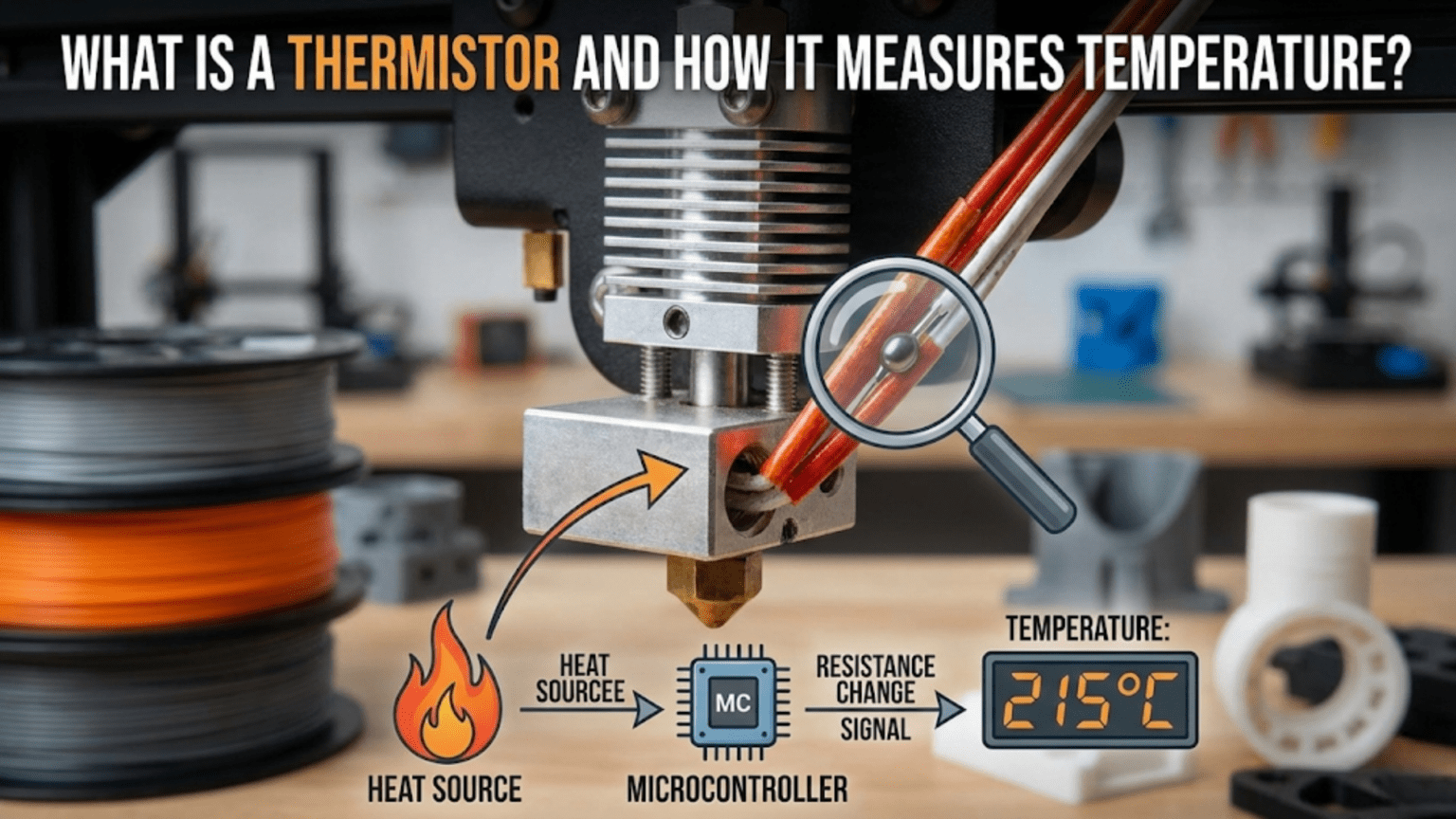
A thermistor is a temperature-dependent resistor that changes its electrical resistance predictably in response to temperature changes, serving as the primary temperature sensing component in 3D printers for both hotends and heated beds. Most 3D printers use NTC (Negative Temperature Coefficient) 100K thermistors that measure 100,000 ohms at 25°C and decrease resistance as temperature increases, with the printer’s mainboard measuring this resistance change and converting it to temperature readings using lookup tables or mathematical formulas, enabling the precise temperature control essential for consistent printing.
Introduction
Every successful 3D print depends on precise temperature control. The plastic must melt at exactly the right temperature—hot enough to flow smoothly but not so hot it degrades. The heated bed must maintain consistent warmth to prevent warping. Even a few degrees of variation can mean the difference between perfect prints and frustrating failures.
Yet temperature itself is invisible. You can’t see whether your hotend is at 200°C or 210°C just by looking. You need a sensor that detects temperature and reports it to the printer’s control system. This is where thermistors come in—tiny glass beads barely visible to the naked eye that change their electrical properties in precise, predictable ways as temperature varies.
These humble temperature sensors might seem like simple components, but they embody sophisticated physics and engineering. Understanding how thermistors work—why resistance changes with temperature, how the printer measures that resistance, and how firmware converts resistance to temperature readings—reveals the foundation of your printer’s thermal control system.
Many users never think about thermistors until they fail. Strange temperature readings appear. PID tuning becomes impossible. Thermal runaway errors trigger mysteriously. Understanding thermistors helps you diagnose these problems, recognize failure symptoms, and maintain this critical component properly.
In this comprehensive guide, we’ll explore exactly what thermistors are, how they detect temperature through resistance changes, why the specific type matters, and how to troubleshoot common thermistor problems. You’ll understand the invisible sensing that makes precise 3D printing possible.
What Is a Thermistor?
The term “thermistor” combines “thermal” and “resistor,” describing exactly what it does:
Basic Principle
A thermistor is a resistor whose resistance varies significantly with temperature. While all resistors show some temperature sensitivity, thermistors are specifically designed and manufactured to have large, predictable resistance changes across useful temperature ranges.
Standard Resistors: Change resistance minimally with temperature—this characteristic is usually undesirable and manufacturers work to minimize it.
Thermistors: Deliberately engineered to maximize the resistance-temperature relationship. The resistance change is the feature, not a bug to eliminate.
This temperature-dependent behavior makes thermistors excellent temperature sensors. By measuring the resistance, you can determine the temperature with high accuracy.
NTC vs. PTC Thermistors
Two main thermistor types exist based on their temperature coefficient:
NTC (Negative Temperature Coefficient): Resistance decreases as temperature increases. These are by far the most common in 3D printing and most temperature sensing applications.
As the thermistor heats up:
- Atomic vibrations increase
- Electrons gain mobility
- Electrical resistance decreases
- Current flows more easily
PTC (Positive Temperature Coefficient): Resistance increases as temperature increases. Less common for temperature sensing, more often used for overcurrent protection or self-regulating heaters.
3D printers universally use NTC thermistors for temperature sensing because they offer:
- High sensitivity (large resistance change per degree)
- Predictable, well-characterized behavior
- Wide useful temperature range
- Low cost and robust construction
The 100K Standard
When 3D printer discussions mention “100K thermistor,” the specification refers to the resistance at a reference temperature:
100K = 100,000 Ohms at 25°C: At exactly 25 degrees Celsius (77°F), the thermistor measures 100,000 ohms of resistance.
This standardization allows interchangeability. Different manufacturers produce 100K thermistors with nearly identical characteristics, enabling replacement and compatibility.
Other Resistance Values: Some applications use different values (10K, 50K thermistors), but 100K dominates 3D printing because it provides:
- Good sensitivity across printing temperatures
- Resistance values easy for electronics to measure accurately
- Standardization across the industry
How Thermistors Work: The Physics
Understanding the underlying physics reveals why thermistors behave as they do:
Semiconductor Material Properties
Thermistors use semiconductor materials—typically metal oxides like manganese, nickel, cobalt, or copper oxides mixed in specific ratios:
Atomic Structure: At the atomic level, these materials have electrons that can potentially conduct electricity, but their availability depends on thermal energy.
Temperature Effects:
- Cold temperatures: Few electrons have sufficient energy to overcome barriers and conduct. High resistance results.
- Hot temperatures: Thermal energy frees more electrons for conduction. Resistance drops significantly.
This relationship is highly nonlinear—resistance doesn’t decrease proportionally with temperature but follows an exponential curve described by the Steinhart-Hart equation (more on this later).
The Physical Construction
A typical NTC thermistor for 3D printing appears as:
The Sensing Element: A tiny bead of sintered semiconductor material, often just 1-2mm in diameter. This small size provides:
- Fast response to temperature changes (low thermal mass)
- Compact installation in tight spaces
- Good thermal contact with the component being measured
Glass Encapsulation: The bead is usually sealed in glass, protecting it from:
- Moisture and contamination
- Mechanical damage
- Chemical exposure
- Electrical shorting
Lead Wires: Two fine wires extend from the bead, connecting to the measurement circuit. These wires are often:
- Very thin (30-36 AWG typically)
- Delicate and prone to breakage if stressed
- Color-coded or unmarked (polarity doesn’t matter for resistive devices)
Insulation: Heat-shrink tubing or similar insulation protects the wires and provides strain relief at connection points.
The Resistance-Temperature Relationship
The relationship between resistance and temperature follows a predictable but complex curve:
Exponential Nature: Resistance changes dramatically at cold temperatures (large ohms-per-degree change) but less dramatically at hot temperatures. The curve isn’t a straight line but an exponential decay.
Steinhart-Hart Equation: Describes the relationship mathematically:
1/T = A + B(ln R) + C(ln R)³
Where:
- T = Temperature in Kelvin
- R = Resistance in ohms
- A, B, C = Constants specific to the thermistor type
- ln = Natural logarithm
This equation allows converting measured resistance to temperature with high accuracy. The firmware or lookup tables use this relationship.
Lookup Tables: Instead of calculating the Steinhart-Hart equation in real-time, most firmware uses pre-calculated lookup tables. These tables contain resistance-to-temperature conversions at regular intervals, with interpolation for values between table entries.
How 3D Printers Measure Thermistor Temperature
The mainboard converts thermistor resistance into a usable temperature reading:
The Voltage Divider Circuit
The thermistor connects to a voltage divider circuit on the mainboard:
Circuit Components:
- Known voltage source (typically 5V or 3.3V)
- Known fixed resistor (often 4.7K ohms)
- Thermistor (unknown resistance that varies with temperature)
- Analog-to-Digital Converter (ADC) measuring the voltage
How It Works:
- Voltage source connects to the series combination of fixed resistor and thermistor
- The voltage divides proportionally based on the resistance ratio
- The voltage between the resistor and thermistor is measured
- This voltage varies with thermistor resistance
- Measuring the voltage reveals the thermistor resistance
Calculation: With known source voltage and fixed resistor value, measuring the voltage at the divider point allows calculating thermistor resistance using Ohm’s law.
From Voltage to Resistance to Temperature
The complete measurement process:
Step 1: ADC Reading: The microcontroller’s ADC (Analog-to-Digital Converter) measures the voltage at the divider point. ADCs typically provide 10-bit or 12-bit resolution, meaning they divide the voltage range into 1024 or 4096 discrete levels.
Step 2: Voltage Calculation: The ADC reading converts to actual voltage: Voltage = (ADC reading / Max ADC value) × Reference voltage
Step 3: Resistance Calculation: Using the voltage divider formula and known fixed resistor value, the thermistor resistance is calculated.
Step 4: Temperature Lookup: The firmware uses the resistance value to look up temperature from its table or calculate it using the Steinhart-Hart equation.
Step 5: Reporting: This temperature value is what you see displayed and what the PID control algorithm uses to regulate heating.
Measurement Frequency
This entire process occurs continuously:
Update Rate: Typical firmware measures thermistor temperature 10-20 times per second. This frequent sampling enables:
- Quick detection of temperature changes
- Responsive PID control
- Fast response to thermal runaway conditions
- Smooth temperature displays
Averaging: Some implementations average multiple readings to reduce noise and provide more stable temperature reports.
Thermistor Types and Specifications
Not all thermistors are identical, even if they’re all “100K NTC”:
Beta Value
The beta value (β) describes the thermistor’s temperature sensitivity:
Definition: Beta represents the material constant in a simplified equation relating resistance and temperature. Higher beta values indicate greater sensitivity.
Common Values: 3950K and 4267K are typical for 3D printer thermistors (the K unit refers to Kelvin, relating to the thermodynamic temperature relationship).
Importance: Thermistors with different beta values have different resistance-temperature curves. Using the wrong beta value in firmware causes temperature reading errors.
Temperature Range
Thermistors have specified operating ranges:
Typical 3D Printer Range: -50°C to 300°C for quality hotend thermistors. Some extend higher for special high-temperature applications.
Accuracy Range: Thermistors perform most accurately in the middle of their range, with decreasing accuracy at extremes.
Beyond Range: Operating outside specified ranges can:
- Reduce accuracy significantly
- Damage the thermistor permanently
- Create safety hazards from inaccurate readings
Response Time
How quickly thermistors respond to temperature changes:
Thermal Time Constant: The time required for the thermistor to reach 63.2% of a step temperature change. Smaller beads respond faster.
Typical Values: 1-3 seconds for small glass bead thermistors in air. Response is faster when mounted in thermally conductive material.
Importance: Fast response enables:
- Quick detection of temperature changes
- More responsive control
- Better thermal runaway protection
Thermistor Installation and Mounting
Proper installation ensures accurate, reliable temperature measurement:
Hotend Installation
Location: The thermistor must sit as close as possible to the melt zone without being in direct contact with the heater cartridge.
Mounting Method:
- Cartridge Style: Some thermistors come in metal cartridges identical in size to heater cartridges. These insert into precision bores in the heater block.
- Bare Bead Style: The glass bead inserts into a smaller precision hole, typically held by a set screw.
Thermal Contact: Critical for accuracy:
- Use thermal paste to fill air gaps between thermistor and heater block
- Ensure the thermistor bead sits firmly in its bore
- Avoid air pockets that insulate the thermistor from actual temperature
Set Screw Caution: When tightening set screws to hold thermistors:
- Apply only gentle pressure
- Excessive force can crack the glass bead
- Crushed thermistor wires cause failures
- Just enough pressure to prevent the thermistor from falling out
Heated Bed Installation
Mounting Options:
- Embedded in PCB heaters: Some heated bed PCBs include integrated thermistors
- Attached to underside: Thermistor taped or glued to the bottom of the aluminum bed
- Mounted in aluminum: Precision hole drilled into bed with thermistor inserted
Thermal Mass Considerations: The bed’s large thermal mass means thermistor location affects readings:
- Center vs edge temperatures can vary significantly
- Distance from heating element affects responsiveness
- Multiple thermistors (if supported) provide better temperature mapping
Adhesion Method: Common approaches include:
- High-temperature tape (Kapton)
- Thermal adhesive or epoxy
- Mechanical retention with clips
- Set screw retention in drilled holes
Thermistor Problems and Troubleshooting
Several failure modes affect thermistors:
Open Circuit (Broken Thermistor)
Symptoms:
- Temperature reading shows maximum (often 999°C, “MAXTEMP” error)
- Temperature won’t rise when heating
- Thermal runaway protection may trigger
- Printer refuses to heat, showing error messages
Causes:
- Broken wire (very common with thin, delicate thermistor wires)
- Disconnected connector
- Cracked or crushed glass bead
- Set screw severing wire
Diagnosis:
- Use multimeter to measure resistance across thermistor leads
- Should read around 100K ohms at room temperature
- Infinite resistance indicates open circuit
Solutions:
- Check connector connections
- Inspect wires for damage, breaks
- Replace thermistor if bead is damaged
- Ensure set screws don’t crush wires
Short Circuit
Symptoms:
- Temperature reading shows minimum (often -15°C or similar, “MINTEMP” error)
- Reading doesn’t change with actual temperature
- Printer won’t heat, reports error
Causes:
- Bare thermistor wires touching each other
- Wires contacting metal heater block
- Damaged insulation
- Moisture intrusion causing conductivity
Diagnosis:
- Multimeter shows zero or very low resistance
- Wiggling wires changes reading erratically
Solutions:
- Inspect insulation for damage
- Ensure wires don’t contact metal components
- Replace thermistor if insulation is compromised
- Check for moisture, dry if necessary
Inaccurate Readings
Symptoms:
- Temperature reading seems wrong (PLA melting at displayed 180°C when set to 200°C)
- PID tuning fails or performs poorly
- Inconsistent behavior between sessions
Causes:
- Wrong thermistor type configured in firmware
- Poor thermal contact (air gaps at thermistor)
- Thermistor near end of life (drifting resistance)
- Electrical interference affecting measurement
Diagnosis:
- Compare displayed temperature to actual melting behavior
- Use infrared thermometer to verify actual temperature
- Check thermistor resistance at room temperature (should be ~100K)
Solutions:
- Verify firmware thermistor type matches actual hardware
- Improve thermal paste application
- Replace aging thermistor
- Route thermistor wires away from heater wires
Intermittent Failures
Symptoms:
- Temperature readings fluctuate erratically
- Occasional MINTEMP or MAXTEMP errors
- Temperature seems to jump randomly
Causes:
- Loose wire connections
- Cracked solder joints
- Damaged wire with intermittent contact
- Vibration causing connector issues
Diagnosis:
- Wiggle wires while watching temperature reading
- Flex connections to trigger intermittent failures
- Check solder joints visually and mechanically
Solutions:
- Secure all connections
- Re-solder questionable joints
- Replace damaged wires
- Add strain relief to prevent wire flexing
Thermistor vs. Thermocouple
Understanding alternative temperature sensors:
Thermocouple Operation
Thermocouples work on different principles:
Construction: Two dissimilar metal wires joined at one end (the sensing junction). When this junction experiences a temperature different from the reference junction, a small voltage is generated.
Voltage Generation: The Seebeck effect creates voltage proportional to temperature difference. Different metal combinations produce different voltage-temperature relationships.
Common Types:
- K-type (Chromel-Alumel): Most common in high-temperature applications
- J-type, T-type: Other standard types for various ranges
Comparison
| Feature | Thermistor (NTC 100K) | Thermocouple (K-type) |
|---|---|---|
| Temperature Range | -50°C to 300°C | -200°C to 1350°C |
| Accuracy | ±1-2°C (with proper calibration) | ±2-5°C |
| Response Time | Fast (1-3 seconds) | Fast (0.5-2 seconds) |
| Cost | Very Low ($1-3) | Low-Moderate ($5-15) |
| Signal Level | High (resistance change) | Low (millivolts) |
| Self-Heating | Minimal with proper circuit | None |
| Linearization | Complex (Steinhart-Hart) | More linear |
| Common Use in 3D Printing | Hotends, heated beds (up to 300°C) | High-temp hotends (>300°C) |
| Durability | Fragile glass bead/wires | More robust |
When to Use Thermocouples:
- Printing materials requiring >300°C (PEEK, Ultem, polycarbonate at high temps)
- Industrial/specialized high-temperature applications
- When extra durability is needed
When to Use Thermistors:
- Standard 3D printing (up to 300°C)
- Cost-sensitive applications
- When simplicity matters
- Standard consumer printers
Firmware Configuration
Thermistors require proper firmware setup:
Thermistor Type Selection
Firmware (Marlin, Klipper, etc.) includes tables for many thermistor types:
Marlin Configuration: Configuration.h includes thermistor type definitions:
#define TEMP_SENSOR_0 1  // Thermistor type for hotend
#define TEMP_SENSOR_BED 1  // Thermistor type for bed
Common Type Numbers:
- 1: Generic 100K thermistor (beta 3950)
- 5: 100K thermistor with beta 4267 (common aftermarket)
- 11: 100K thermistor (beta 3950) for hotends
- Many others for specific manufacturer thermistors
Importance: Using the wrong thermistor type causes temperature reading errors. A few degrees difference might seem minor but affects:
- PLA flowing properly vs being too viscous
- PETG bonding well vs stringing excessively
- Temperature stability and PID control
Custom Thermistor Tables
For non-standard thermistors:
Beta Value Method: If you know the beta value, Marlin can calculate the table from that parameter.
Custom Table Definition: For maximum accuracy, define a custom table with resistance-temperature pairs at known points.
Calibration: Some users calibrate thermistors against known temperature sources, creating custom tables for their specific hardware.
Maintenance and Lifespan
Thermistors require minimal but important care:
Preventive Maintenance
Wire Protection:
- Avoid sharp bends near the glass bead
- Provide strain relief at connections
- Protect wires from heat, abrasion, and tension
- Route away from moving parts that could snag
Connection Security:
- Ensure connectors seat firmly
- Check terminal screw tightness periodically
- Prevent wire movement at connection points
Environmental Protection:
- Keep moisture away from thermistors
- Avoid excessive heat exposure beyond rating
- Protect from mechanical damage
Expected Lifespan
Typical Life: With proper care, thermistors can last years or even the printer’s entire life.
Failure Modes: When they fail, it’s usually:
- Wire breakage from flexing or stress
- Connector corrosion or damage
- Rarely, glass bead degradation or resistance drift
Replacement Timing:
- Preventively when installing new hotends
- Immediately upon any temperature reading anomaly
- After any physical damage to wiring
Cost Consideration: At $1-3 each, thermistors are among the cheapest components. When in doubt, replace rather than troubleshoot extensively.
Advanced Thermistor Concepts
Self-Heating Effects
Passing current through the thermistor to measure resistance generates slight heat:
Phenomenon: The measurement current causes power dissipation (I²R heating) in the thermistor itself, slightly raising its temperature above ambient.
Mitigation: Using high resistance thermistors (100K) with voltage dividers using even higher fixed resistors minimizes current, reducing self-heating to negligible levels (typically <0.1°C error).
Noise and Filtering
Thermistor signals can pick up electrical noise:
Interference Sources:
- Heater switching (high currents turning on/off)
- Motor driver PWM signals
- Radio frequency interference
Filtering: Mainboards typically include capacitor filtering on thermistor inputs to smooth noisy readings.
Wire Routing: Keeping thermistor wires separated from high-power wiring reduces induced noise.
Multi-Point Sensing
Some advanced setups use multiple thermistors:
Bed Temperature Mapping: Multiple bed thermistors reveal temperature gradients, allowing:
- Zone-specific heating control
- Compensation for uneven heating
- Detection of heating element failures
Hotend Redundancy: Dual thermistors provide backup temperature sensing for safety-critical applications.
Conclusion
Thermistors might be tiny, inexpensive components, but they perform the critical function of temperature sensing that enables your printer’s precise thermal control. Understanding how these temperature-dependent resistors work—changing resistance exponentially with temperature in predictable ways governed by semiconductor physics and the Steinhart-Hart equation—reveals the foundation of temperature measurement in 3D printing.
The journey from physical temperature to displayed reading involves sophisticated electronics and firmware: voltage dividers measuring resistance, analog-to-digital conversion, and lookup tables or mathematical formulas translating resistance to temperature. This happens continuously, many times per second, providing the feedback that PID control algorithms use to maintain steady temperatures within a few degrees.
When thermistors fail—and they do fail, usually from broken wires or damaged beads—the symptoms are often obvious: MAXTEMP or MINTEMP errors, impossible temperature readings, or erratic fluctuations. Understanding these failure modes helps you diagnose problems quickly rather than wasting time troubleshooting other components.
Proper installation with good thermal contact, protected wiring, and gentle set screw tightening ensures reliable operation. Correct firmware configuration matching your thermistor’s actual type and beta value provides accurate temperature readings. These simple practices prevent most thermistor problems.
The next time you set your printing temperature and watch the display rise smoothly to your target, appreciate the humble thermistor making it possible. That tiny glass bead with its carefully formulated semiconductor material and delicate wires is silently measuring temperature dozens of times per second, providing the critical feedback that transforms electrical heating into precisely controlled thermal environments where your designs become reality.