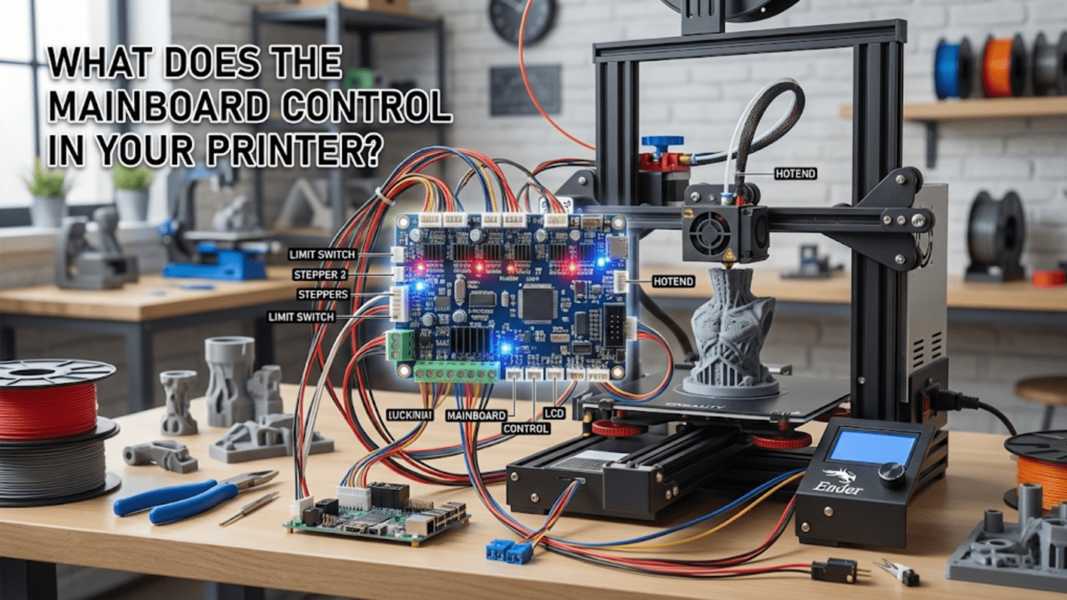
The mainboard (also called the control board or motherboard) serves as the central nervous system of a 3D printer, containing the microcontroller that executes firmware, stepper motor drivers that control precise movements, power regulation circuits, input/output interfaces for sensors and heaters, and communication ports for receiving G-code commands. It orchestrates all printer functions by reading sensor inputs (thermistors, endstops, probes), executing motion control algorithms, regulating temperatures through PWM heater control, managing user interface displays, and coordinating the complex timing required to transform digital designs into physical objects.
Introduction
If you were to identify the brain of your 3D printer, the mainboard would be it. This circuit board—often hidden away in an electronics enclosure beneath or behind the printer—contains the intelligence that transforms G-code instructions into coordinated actions. Every motor movement, every degree of heating, every sensor reading, every user interface interaction flows through this central command center.
Yet the mainboard’s critical role remains invisible during normal operation. You interact with temperature settings, movement commands, and print files, but you rarely think about the circuit board making it all happen. The mainboard silently interprets your commands, coordinates timing across multiple systems, monitors for error conditions, and maintains the precise control that quality printing demands.
Understanding what the mainboard actually does—how it controls stepper motors, regulates temperatures, processes sensor inputs, and manages communication—transforms it from a mysterious black box into a comprehensible control system. You’ll recognize why certain mainboards support features others don’t, understand the symptoms of mainboard problems, and make informed decisions about upgrades or replacements.
In this comprehensive guide, we’ll explore every major function the mainboard performs, examining the components that enable these functions and understanding how they work together to create a functional 3D printer from individual parts.
The Microcontroller: The Brain of Operations
At the heart of every mainboard sits a microcontroller—a small computer on a chip:
What Microcontrollers Do
Processing: The microcontroller executes firmware code, making thousands of decisions per second:
- Interpreting G-code commands
- Calculating motor step timing
- Reading sensor values
- Adjusting heater power
- Updating displays
- Managing communication
Real-Time Operation: Unlike general computers that can delay tasks, microcontrollers operate in real-time. Motor steps must occur at precise intervals measured in microseconds. Temperature must be sampled and controlled continuously. Any delay creates problems.
Resource Constraints: Microcontrollers have limited resources compared to computers:
- Processing speed: Typically 48-180 MHz (vs. GHz in computers)
- Memory: 256-512KB of program storage, 32-256KB of RAM
- No operating system overhead—firmware runs directly on hardware
Common Microcontroller Families
8-bit AVR (Older Printers):
- ATmega2560: Popular in Arduino Mega-based boards
- 16 MHz clock speed
- 256KB program memory, 8KB RAM
- Adequate for basic printing but limited for complex features
- Marlin firmware sometimes fills available memory completely
32-bit ARM Cortex (Modern Printers):
- STM32F103, STM32F4xx series: Most common in current boards
- 72-168 MHz clock speeds
- 512KB-1MB+ program memory, 64-256KB+ RAM
- Much more capable—handles advanced features easily
- Allows faster motion planning and more sophisticated algorithms
Performance Impact: More powerful microcontrollers enable:
- Higher print speeds through better motion planning
- More complex features (linear advance, input shaping in some implementations)
- Smoother operation with less stuttering
- Support for larger G-code buffers
Stepper Motor Control
One of the mainboard’s primary functions is precise motor control:
Motor Driver Integration
The mainboard contains or connects to stepper motor drivers:
Integrated Drivers: Modern boards include drivers soldered directly:
- Common chips: A4988, DRV8825, TMC2208, TMC2209, TMC5160
- Each driver controls one motor
- Typical boards have 4-5 drivers (X, Y, Z, E, sometimes dual Z)
Removable Drivers: Older designs use socketed drivers:
- Drivers plug into standardized sockets
- Allows upgrading drivers independently
- Can replace failed drivers easily
- Less common in modern integrated designs
Step and Direction Signals
The microcontroller sends two critical signals to each driver:
Step Signal: Each pulse tells the driver to advance one step:
- Pulse frequency determines motor speed
- Faster pulses = faster rotation
- Microcontroller generates precisely timed pulse trains
- Can generate thousands of pulses per second per motor
Direction Signal: Indicates which direction to rotate:
- High/low signal determines direction
- Changes when movement reverses
- Held steady during continuous movement in one direction
Current Regulation
Drivers must regulate current to appropriate levels:
Configuration Methods:
- Potentiometer adjustment on driver (older designs)
- Digital configuration via firmware (TMC drivers with UART/SPI)
- Sets maximum current delivered to motor
Importance: Correct current ensures:
- Adequate motor torque
- Prevents overheating
- Avoids skipped steps or motor damage
Current Settings: Typically configured in firmware or via physical adjustment to match motor specifications (often 1.0-1.7A for NEMA 17 motors).
Microstepping Configuration
Drivers divide full steps into smaller microsteps:
Configuration:
- Jumpers on some boards (setting 1/16, 1/32, etc.)
- Firmware configuration on integrated designs
- Common setting: 1/16 microstepping
Benefits:
- Smoother motor operation
- Quieter movement
- Finer positioning resolution
- Reduced resonance issues
Temperature Control Systems
The mainboard manages all thermal aspects of printing:
Heater Control via PWM
Power Switching: The mainboard controls heaters through MOSFETs or relays:
- MOSFET (solid-state switch) for most applications
- Relay for very high-current bed heaters
- External MOSFETs for high-power heaters exceeding board rating
PWM (Pulse Width Modulation):
- Rapidly switches heater power on and off
- Duty cycle (percentage “on”) controls average power
- 100% duty = maximum heating
- 50% duty = half power
- 0% duty = off
Frequency: Typical PWM frequencies:
- Hotend: 10-30 Hz
- Heated bed: 10-30 Hz (some use slower rates)
PID Temperature Regulation
The microcontroller implements PID control algorithms:
Continuous Monitoring:
- Reads thermistor values 10-20 times per second
- Converts resistance to temperature
- Compares to target temperature
PID Calculation:
- Proportional: How far from target?
- Integral: Accumulated error over time
- Derivative: Rate of temperature change
- Calculates optimal PWM duty cycle
Dynamic Adjustment: PID constantly adjusts heater power to:
- Reach target temperature quickly
- Maintain stable temperature (±1-2°C)
- Prevent overshoot
- Respond to changing conditions (filament flow, cooling fan activation)
Multiple Temperature Zones
Modern boards support multiple independent temperature controls:
Standard Configuration:
- Hotend (extruder 0)
- Heated bed
- Each with independent thermistor input and heater output
Multi-Extruder Systems:
- Additional hotend thermistors and heaters
- Independently controlled
- Firmware manages tool changes
Advanced Systems:
- Chamber heating (if supported)
- Multi-zone heated beds
- Separate heating channels for different functions
Safety Features
The mainboard implements critical thermal safety:
Thermal Runaway Protection:
- Monitors whether temperature responds correctly to heating
- Triggers if temperature doesn’t rise when heater activates
- Shuts down if temperature exceeds target excessively
- Prevents fires from thermistor failures or disconnections
Min/Max Temperature Limits:
- Enforces minimum temperatures (prevents detecting disconnected thermistors as valid)
- Enforces maximum safe temperatures
- Immediately shuts down heating if limits exceeded
Temperature Verification:
- Confirms thermistor readings are physically possible
- Detects short circuits (impossibly low readings)
- Detects open circuits (impossibly high readings)
Input/Output Management
The mainboard interfaces with numerous sensors and peripherals:
Endstop and Limit Switch Inputs
Digital Inputs: Read endstop switch states:
- Typically 3-6 endstop inputs (X min/max, Y min/max, Z min/max)
- Detect switch closures during homing
- May include pull-up resistors for reliable reading
- Configured in firmware for normally open or normally closed logic
Debouncing: Software filters out switch bounce to prevent false triggers.
Verification: Firmware verifies endstops function during startup or homing sequences.
Probe and Sensor Inputs
Bed Leveling Probes:
- Inductive, capacitive, or BLTouch-style probes
- Various input types depending on probe (analog or digital)
- May share pins with endstops or use dedicated inputs
Filament Sensors:
- Detect filament presence or motion
- Simple switch-based or optical/encoder types
- Trigger pause when filament runs out or jams
Fan and Peripheral Outputs
Multiple Fan Channels:
- Hotend cooling fan (often always-on)
- Part cooling fan (variable speed, PWM controlled)
- Additional fans for electronics or chamber cooling
- Each with dedicated MOSFET driver
PWM Speed Control:
- Variable speed fans use PWM signals
- Firmware controls duty cycle based on slicer commands or conditions
- Typically 25 kHz PWM for fan control (inaudible frequency)
Other Outputs:
- LED lighting control
- Power switching for accessories
- Additional heater outputs (chamber, etc.)
Communication and Connectivity
The mainboard provides various communication interfaces:
USB/Serial Communication
Computer Connection:
- USB port connects to computer
- Serial protocol (typically Marlin protocol)
- Allows real-time control via host software
- Bidirectional communication (commands in, status out)
Communication Speed:
- Baud rates typically 115200 or 250000
- Higher rates allow faster command transmission
- Must match between printer and host software
Use Cases:
- Sending G-code directly from computer
- Firmware updates
- Real-time control (OctoPrint, Repetier-Host, etc.)
- Diagnostic and configuration access
SD Card Interface
Untethered Printing:
- SD card slot for standalone operation
- Reads G-code files from card
- Allows printing without computer connection
- Typically supports SD and SDHC cards (up to 32GB)
File System:
- FAT32 format most common
- Firmware browses files, displays list on screen
- Handles file reading during printing
Network Connectivity
WiFi (Some Boards):
- ESP8266 or ESP32 module integration
- Enables wireless G-code transmission
- Web interface access
- Remote monitoring
Ethernet (Rare in Consumer Printers):
- Wired network connection
- More stable than WiFi
- Common in industrial/professional machines
Expansion Headers
GPIO (General Purpose Input/Output):
- Additional pins exposed for expansion
- Allows adding custom sensors or outputs
- Typically accessed through JST connectors or pin headers
I²C, SPI Interfaces:
- Serial communication protocols
- Connect additional devices (displays, sensors, expanders)
- Allow modular expansion
Display and User Interface Control
The mainboard manages user interaction:
Display Interfaces
Character LCDs:
- Simple 16×2 or 20×4 character displays
- Controlled via parallel interface or I²C
- Shows temperatures, print progress, menus
Graphic LCDs:
- 128×64 pixel monochrome displays common
- Allows icons, graphics, more information
- Controlled via SPI or parallel interface
Color Touchscreens:
- TFT displays with touch input
- More sophisticated interfaces possible
- May use dedicated serial protocols
- Some use independent processors
Input Devices
- Knob for menu navigation
- Rotation detected by quadrature signals
- Integrated button for selection
- Firmware interprets pulses for menu scrolling
Buttons:
- Simple momentary switches
- Debounced in firmware
- Used for direct functions or menu navigation
Touchscreen Input:
- Resistive or capacitive touch detection
- Coordinates sent to firmware
- Enables graphical interface interaction
Menu Systems
The firmware provides menu structures:
- Navigate settings
- Initiate functions (homing, bed leveling, load filament)
- Adjust parameters (temperatures, speeds, offsets)
- View information (print progress, statistics)
Mainboard Types and Capabilities Comparison
| Board Type | Microcontroller | Drivers | Typical Features | Best For |
|---|---|---|---|---|
| 8-bit Basic | ATmega2560 | Socketed A4988 | Basic printing, limited memory | Budget builds, simple printers |
| 8-bit Advanced | ATmega2560 | Integrated TMC | Better features, still limited | Mid-range 8-bit printers |
| 32-bit Budget | STM32F103 | Integrated TMC2208 | Good performance, affordable | Modern budget printers |
| 32-bit Standard | STM32F4xx | Integrated TMC2209 | Excellent performance, quiet | Quality consumer printers |
| 32-bit Advanced | STM32F4/F7 | TMC5160 or flexible | Maximum features, expandable | Enthusiast/custom builds |
| High-End | STM32H7, LPC | Advanced drivers | Professional features, networking | Professional/industrial |
Common Mainboard Problems
No Power/Dead Board
Symptoms: No lights, no response, completely dead.
Causes:
- Blown fuse on input
- Failed voltage regulator
- Shorted components
- Power supply failure (not board)
Diagnosis:
- Verify power supply outputs correct voltage
- Check board input fuse
- Look for visible damage (burned components, blown capacitors)
- Measure voltage at regulator outputs
Intermittent Operation
Symptoms: Random resets, disconnections, erratic behavior.
Causes:
- Insufficient power supply capacity
- Loose connections
- Overheating components
- Electromagnetic interference
Solutions:
- Verify adequate PSU wattage
- Secure all connections
- Improve cooling
- Add ferrite beads on cables if interference suspected
Motor Issues
Symptoms: Motors not moving, stuttering, skipping steps.
Causes:
- Failed motor driver
- Incorrect current settings
- Loose connections
- Overheating drivers
Diagnosis:
- Swap driver channels (if socketed) to isolate problem
- Measure driver current output
- Check driver heatsink temperature
- Verify motor wiring
Temperature Control Failures
Symptoms: Temperatures not responding, runaway errors, inaccurate readings.
Causes:
- Thermistor failure or disconnection
- Failed MOSFET
- Wrong thermistor type in firmware
- Damaged heater wiring
Diagnosis:
- Test thermistor resistance
- Verify heater resistance
- Check MOSFET continuity
- Confirm firmware thermistor configuration
Upgrading Mainboards
Consider upgrades for enhanced capabilities:
When to Upgrade
Performance Needs:
- Faster printing requiring better motion planning
- Advanced features (linear advance, input shaping)
- Quieter operation (better drivers)
Compatibility Issues:
- Current board doesn’t support needed features
- Insufficient expansion capacity
- Outdated firmware with limited development
Reliability Concerns:
- Aging board with intermittent issues
- Known problems with current board model
- Desire for better safety features
Selection Criteria
Microcontroller: 32-bit ARM recommended for modern capabilities.
Driver Support:
- TMC2209 or better for quiet operation
- Sufficient drivers for all motors (including dual Z if needed)
Expansion:
- Adequate inputs for all sensors
- Sufficient outputs for heaters and fans
- Room for future additions
Form Factor:
- Must fit printer’s electronics enclosure
- Compatible mounting holes
- Accessible connectors
Firmware Support:
- Marlin compatibility (most common)
- Active development community
- Documentation quality
Popular Upgrade Boards
SKR Series (BigTreeTech):
- Various models (Mini E3, 1.4, 2.0, Pro, etc.)
- 32-bit ARM processors
- Integrated TMC drivers common
- Good Marlin support
- Affordable pricing
Duet Boards:
- High-end features
- Excellent RepRapFirmware
- Network connectivity
- Professional quality
- Premium pricing
MKS Boards:
- Wide range of options
- Competitive pricing
- Variable quality (research specific models)
- Marlin compatible
Firmware and Mainboard Relationship
The firmware determines what the hardware can do:
Firmware Compilation
Configuration:
- Firmware must be configured for specific board
- Pin assignments match board layout
- Feature enablement based on hardware capability
- Driver types specified
Compilation Process:
- Source code compiled for specific microcontroller
- Creates firmware binary
- Upload via USB or SD card bootloader
Updating Firmware
When to Update:
- Bug fixes
- New features
- Hardware changes requiring configuration updates
- Performance improvements
Backup First:
- Save current configuration
- Document custom settings
- Export EEPROM values
Testing After Update:
- Verify all functions work
- Check motor directions
- Confirm temperature control
- Test endstops
Conclusion
The mainboard serves as the command center orchestrating every aspect of your 3D printer’s operation. Its microcontroller executes firmware that interprets G-code, calculates precise motor timing, regulates temperatures through sophisticated PID algorithms, monitors sensors for error conditions, and manages user interactions. The motor drivers it controls or contains create the precise movements building your objects layer by layer. The power regulation and switching circuits it provides convert control signals into the current needed to heat elements and drive peripherals.
Understanding what the mainboard does—and how it does it—transforms this circuit board from a mysterious component into a comprehensible control system. You recognize why 32-bit boards outperform older 8-bit designs, understand what TMC drivers provide that older drivers don’t, and appreciate the complex timing and coordination happening thousands of times per second during every print.
When problems arise, this knowledge helps you diagnose whether the issue stems from the mainboard, firmware configuration, or external components. You can evaluate upgrade options based on actual capabilities rather than marketing claims, selecting boards that provide the features you need at quality levels matching your requirements.
The next time you start a print and watch your printer spring to life—motors homing precisely, heaters warming smoothly, display showing status clearly—appreciate the mainboard making it all possible. That circuit board isn’t just a collection of electronic components; it’s the intelligence coordinating dozens of subsystems into a harmonious system that transforms digital dreams into physical reality.