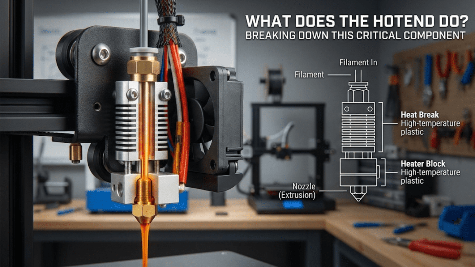
The hotend is the component in a 3D printer that melts solid filament into a viscous liquid state and precisely extrudes it through a small nozzle opening to create printed objects layer by layer. It consists of a heating element, heat break, heat sink, thermistor for temperature sensing, and a nozzle, all working together to create a controlled melting zone that transforms room-temperature plastic into printable material.
Introduction
If you were to identify the single most critical component in an FDM 3D printer, the hotend would be a strong contender. This seemingly simple assembly performs the fundamental transformation that makes 3D printing possible—converting solid plastic filament into precisely controlled molten material that can be deposited layer by layer to create three-dimensional objects.
Yet despite its importance, the hotend remains one of the most misunderstood components for beginners. What exactly happens inside that metal assembly? Why does it have so many parts? How does it melt plastic without jamming? And why do different hotends produce different results?
In this comprehensive guide, we’ll dismantle the hotend piece by piece, examining each component’s role and understanding how they work together. By the end, you’ll have a complete understanding of this critical component, enabling you to troubleshoot problems, make informed upgrade decisions, and optimize your printing results.
The Hotend’s Primary Function: Controlled Melting
At its core, the hotend has one primary job: create a precisely controlled melt zone where solid filament transforms into liquid plastic that can be extruded through a small opening. This sounds simple, but the engineering challenges involved make it remarkably complex.
The hotend must accomplish several competing objectives simultaneously. It needs to melt plastic completely so it flows smoothly through the nozzle. However, it must keep the melting confined to a small zone—if heat travels too far up the filament path, the filament softens prematurely and jams. The hotend must maintain rock-steady temperatures despite constantly introducing cool filament and blowing cooling air on the printed part nearby. It needs to provide enough thermal mass to melt filament at your desired flow rate without cooling down, yet it should heat up quickly when you start printing.
Think of the hotend as a precision heat exchanger. Cold filament enters from above, passes through a thermal transition zone, gets heated to its melting point, becomes fully molten, and exits through a precision orifice—all within a space smaller than your thumb. This process happens continuously during printing, with the extruder motor pushing new filament in at precisely the rate needed to maintain your desired extrusion volume.
The temperature control precision required is substantial. Most plastics have relatively narrow temperature windows where they flow properly. Too cool, and the plastic remains too viscous, creating excessive back-pressure that can cause the extruder to skip steps or grind through the filament. Too hot, and the plastic degrades chemically, creating nozzle clogs from carbonized material and producing weak, brittle prints with poor surface quality.
Different filament materials require vastly different temperatures. PLA typically prints around 190-220°C, while ABS prefers 230-250°C. Specialty materials like polycarbonate demand temperatures above 270°C, and some engineering plastics require 300°C or higher. The hotend must accommodate these varying requirements while maintaining ±2°C temperature stability during active printing.
The Complete Hotend Assembly: Understanding Each Component
The Heat Sink: Creating the Cold Zone
The heat sink represents the top portion of the hotend assembly, and its job is counterintuitive—it actively works to stay cold while attached to a component generating intense heat. This cooling function is critical because the heat sink defines where the cold zone ends and the hot zone begins.
Most heat sinks are machined from aluminum due to its excellent thermal conductivity and light weight. The design features extensive fins or fins arranged in patterns that maximize surface area exposed to airflow. More surface area means more efficient heat dissipation, allowing the heat sink to maintain lower temperatures.
The heat sink geometry typically includes a threaded hole or smooth bore where the heat break (which we’ll discuss next) threads in or presses. The attachment between heat sink and heat break represents a critical junction—it must be mechanically secure while minimizing thermal conduction from the hot zone below.
Some heat sinks incorporate additional features like mounting holes for attaching to the printer’s carriage, threaded holes for securing cooling fans, or integrated mounting points for the cooling duct that directs airflow onto the printed part. The mechanical design must balance cooling efficiency with compact size and low weight, since the hotend assembly moves during printing.
Heat sink orientation affects cooling efficiency. Vertical fins aligned with airflow work better than horizontal fins that create turbulence. The fin spacing represents a compromise—closer fins provide more surface area but can impede airflow, while widely spaced fins allow better airflow but reduce surface area.
The Cooling Fan: Active Temperature Management
The heat sink alone cannot reject enough heat to prevent heat creep (where heat travels up the filament path causing jams). An active cooling fan provides forced airflow that dramatically increases the heat sink’s cooling capacity.
Most hotends use small axial fans, commonly 30mm or 40mm diameter, running continuously whenever the printer operates. Unlike the part cooling fan that blows on the printed object and runs at variable speeds, the hotend cooling fan typically operates at 100% speed at all times.
The fan specification matters. CFM (cubic feet per minute) rating indicates airflow volume—higher values mean more air movement and better cooling. However, higher airflow fans often produce more noise. Static pressure rating becomes relevant when the fan must push air through the heat sink fins, which create resistance.
Fan quality dramatically affects reliability. The hotend cooling fan is one of the few components that runs continuously during printing, potentially accumulating thousands of hours. Cheap fans fail prematurely, and when this fan fails, heat creep causes jams within minutes. Many experienced users replace stock fans with higher-quality alternatives (like Sunon or Noctua models) for reliability and quieter operation.
The fan mounting must direct airflow across the heat sink fins effectively. Some designs use shrouds or ducts to ensure air flows through the fins rather than around them. Poor fan alignment can leave portions of the heat sink inadequately cooled, creating hotspots that allow heat creep.
The Heat Break: Thermal Barrier Engineering
The heat break might be the most critical component in the entire hotend assembly. This small piece of precisely machined metal creates the thermal barrier between the cold zone (where filament must remain solid) and the hot zone (where melting occurs). The engineering challenges it solves are substantial.
Heat breaks are typically manufactured from stainless steel or titanium—materials chosen specifically for their poor thermal conductivity. While this seems counterintuitive (we normally want good heat conduction in mechanical components), poor thermal conductivity is exactly what’s needed here to prevent heat from traveling upward.
The geometry of a heat break features a thin-walled section with minimal cross-sectional area. Heat conduction is proportional to cross-sectional area, so reducing this area minimizes heat transfer. However, the heat break must still provide sufficient mechanical strength to hold the hotend assembly together and withstand the forces involved in pushing filament through a restrictive nozzle.
Inside the heat break, a precisely machined bore allows filament to pass through smoothly. The internal diameter must accommodate the filament (typically 1.75mm or 2.85mm) with minimal clearance to prevent molten plastic from traveling upward, yet enough clearance that solid filament doesn’t bind. Surface finish matters tremendously—any rough spots or steps can catch molten plastic and initiate a jam.
Two main heat break design philosophies exist:
PTFE-lined heat breaks incorporate a PTFE (Teflon) tube running through the entire length. The PTFE provides an extremely slippery surface that prevents molten plastic from sticking. This design enables reliable printing even with less precise manufacturing tolerances. However, PTFE begins degrading above 240°C, limiting the maximum operating temperature and preventing use with high-temperature materials.
All-metal heat breaks eliminate the PTFE, using only precisely machined metal surfaces for the filament path. This allows printing at any temperature the heater and thermistor can achieve—often up to 300°C or beyond. However, the design requires exceptional manufacturing precision since there’s no slippery PTFE to compensate for imperfections. Molten plastic can stick to metal surfaces more readily than PTFE, making all-metal hotends slightly more prone to jamming if not designed and operated correctly.
Some modern heat breaks incorporate additional innovations. Internal grooves increase surface area exposed to cooling airflow passing through the heat sink while maintaining minimal cross-sectional area for heat conduction. Bi-metal designs use different materials for the upper and lower sections, optimizing each for its specific thermal requirements.
The threaded connections where the heat break attaches to the heat sink above and heater block below require careful assembly. Thread engagement must be sufficient for strength, and thermal paste often fills any air gaps to improve heat transfer characteristics. However, you don’t want excessive heat transfer to the heat sink—the goal is creating a sharp temperature gradient across the heat break itself.
The Heater Block: Thermal Mass and Heat Distribution
Below the heat break, the heater block provides the mass necessary to store thermal energy and maintain stable temperatures. Machined from aluminum for its excellent thermal conductivity, the heater block accepts the heating element, thermistor, nozzle, and heat break connection.
Heater block size involves engineering tradeoffs. Larger blocks provide more thermal mass, maintaining temperature stability when cool filament constantly flows through. This prevents temperature fluctuations during printing, especially at higher flow rates. However, larger blocks take longer to heat up initially and cool down when you finish printing. Smaller blocks heat and cool quickly but may struggle to maintain temperature during rapid extrusion.
Standard heater blocks measure approximately 20mm x 20mm x 10mm, though variations exist. The block features precision-drilled bores for:
- Heater cartridge: A cylindrical hole, typically 6mm in diameter, accepts the heating element
- Thermistor: A smaller hole (often 3mm) positions the temperature sensor near the heating element and melt zone
- Nozzle thread: A threaded hole (commonly M6) where the nozzle screws in
- Heat break thread: Another threaded hole where the heat break attaches from above
The positioning of these bores affects performance. The heater cartridge and thermistor should sit as close together as practical, ensuring the temperature sensor accurately measures the temperature in the zone being heated. The nozzle position needs to allow the heat break to seal properly against the nozzle’s interior, creating the melt chamber.
Some heater blocks include additional features:
Silicone socks are removable insulating covers that slip over the heater block. These bright-colored silicone sleeves provide several benefits. They insulate the block, reducing heat loss and improving temperature stability. They protect the block from plastic drips and blobs that inevitably occur, making cleanup easier. They prevent the part cooling fan’s airflow from cooling the heater block itself.
Set screw holes secure the heater cartridge and thermistor in their bores. These tiny threaded holes accept small set screws (typically M3) that clamp the components in place. Proper tightening is critical—too loose and components can slip or fall out during operation, too tight and you might damage delicate thermistor wires or crack the heater cartridge.
Heater block design variations exist for specialized applications:
Volcano heater blocks extend the length of the melt zone, increasing the volume of molten plastic available. This allows higher flow rates for faster printing, though it requires special longer nozzles designed to work with the extended block.
Cyclops and Chimera blocks incorporate multiple heater cartridges, thermistors, and nozzles for multi-material or multi-color printing from a single assembly.
The Heating Element: Power to Temperature Conversion
The heating element converts electrical power into thermal energy. Cartridge heaters represent the standard choice—cylindrical metal cases containing a resistive wire embedded in ceramic insulation. When current flows through the resistive wire, it generates heat according to Joule’s law (power equals current squared times resistance).
Standard cartridge heaters measure 6mm in diameter and 20mm in length, though other sizes exist. Power ratings typically range from 30 to 60 watts for standard applications. The power rating determines how quickly the hotend can heat up and how much thermal load it can sustain during printing.
A 40-watt heater provides adequate performance for most printing scenarios at normal speeds. When you’re printing with standard nozzle sizes (0.4mm) at typical speeds (40-60 mm/s), the heater can easily maintain temperature. However, if you want to print faster or use larger nozzles that extrude more plastic per second, a higher wattage heater helps maintain temperature stability.
The heater cartridge connects to the printer’s mainboard via two wires. These wires must be appropriately gauged for the current they’ll carry—inadequate wire gauge creates resistance that wastes power and generates heat in the wires themselves. Proper strain relief prevents the wires from breaking due to repeated flexing as the hotend moves.
The mainboard controls heater power using PWM (Pulse Width Modulation). Rather than varying voltage, the controller rapidly switches the heater fully on and fully off, varying the percentage of time it’s on. A PID (Proportional-Integral-Derivative) control algorithm calculates the appropriate power level needed to reach and maintain target temperature.
Heater cartridges eventually fail. The resistive wire can break from thermal cycling, the ceramic insulation can crack, or the metal case can corrode. Replacement is straightforward but requires heating the hotend to release the thermal expansion lock between cartridge and heater block.
The Thermistor: Temperature Measurement and Control
Accurate temperature measurement is essential for successful printing. The thermistor provides this measurement—a temperature-dependent resistor whose resistance changes predictably with temperature.
Most 3D printer hotends use NTC (Negative Temperature Coefficient) thermistors, specifically the 100K type. The “100K” indicates the thermistor measures 100,000 ohms resistance at 25°C. As temperature increases, resistance decreases in a well-characterized curve documented in lookup tables.
The thermistor comes as a tiny glass bead (typically 2-3mm diameter) with two extremely fine wires extending from it. This assembly inserts into its precision bore in the heater block, positioned as close as practical to both the heater cartridge and the melt zone. Thermal paste fills any air gaps, ensuring good thermal contact between the thermistor bead and the surrounding aluminum.
The mainboard’s thermistor circuit sends a small reference current through the thermistor and measures the resulting voltage. Using Ohm’s law and the known reference resistance, the firmware calculates the thermistor’s resistance, then uses a lookup table to convert this resistance to temperature. This process occurs hundreds of times per second, providing continuous temperature feedback.
Thermistor accuracy affects print quality significantly. If the thermistor reads too high, the actual temperature will be lower than intended, causing under-extrusion and poor layer adhesion. Reading too low means excessive temperature, potentially degrading the plastic and creating stringing issues.
Several factors can cause thermistor errors:
Poor thermal contact between the thermistor bead and heater block creates a temperature offset. The thermistor reads cooler than the actual nozzle temperature because heat must conduct through an air gap or insufficient thermal paste.
Electrical interference from nearby heater wires can inject noise into the sensitive thermistor signal. Proper wire routing keeps thermistor wires separated from heater wires, and twisted-pair construction helps reject common-mode interference.
Physical damage to the tiny thermistor wires causes intermittent readings or complete failure. The wires are extremely delicate—overtightening the set screw or snagging the wires can break them.
Some high-end hotends use thermocouples instead of thermistors. These devices generate a small voltage proportional to temperature and can measure much higher temperatures (600°C+) than thermistors. However, they cost more and require different mainboard circuitry.
The Nozzle: Precision Extrusion Orifice
The nozzle represents the final component in the hotend assembly where molten plastic exits to form your print. This small brass (or alternative material) component dramatically influences print quality and capabilities.
Nozzle design features several critical dimensions:
Orifice diameter determines the width of extruded plastic. Standard 0.4mm nozzles balance detail capability with reasonable print times. Smaller nozzles (0.2mm, 0.3mm) produce finer detail but print more slowly since each extrusion path is narrower. Larger nozzles (0.6mm, 0.8mm, 1.0mm+) enable faster printing of large objects but sacrifice fine detail.
Thread size and pitch must match the heater block’s threaded hole. M6 threads (6mm diameter) are most common, though some designs use M7 or other sizes. The thread depth determines how far the nozzle extends into the heater block.
Overall length varies by design. Standard nozzles work with regular heater blocks, while Volcano nozzles extend longer to accommodate the extended Volcano heater block design.
Exterior taper angle affects how close the nozzle can get to previously printed features. A more aggressive taper (steeper angle) allows printing steeper overhangs before the nozzle body hits the part.
Inside the nozzle, the geometry transitions from the filament diameter down to the orifice size. This internal profile affects flow resistance and print quality. Better nozzles feature smooth internal transitions without sharp steps that could cause turbulence or create opportunities for plastic to stick.
Nozzle material selection depends on your printing needs:
Brass offers excellent thermal conductivity, machines easily, and costs little. It represents the standard choice for most applications. However, brass wears quickly when printing abrasive filaments containing carbon fiber, metal particles, or other hard additives.
Hardened steel resists wear from abrasive materials, lasting much longer than brass with these filaments. The tradeoff involves lower thermal conductivity—you typically need to increase your printing temperature by 5-10°C when using hardened steel nozzles.
Stainless steel provides some wear resistance while maintaining better thermal conductivity than hardened steel. It represents a middle ground between brass and hardened steel.
Plated nozzles start with brass for thermal conductivity but add surface coatings for wear resistance or release properties. Nickel-plated nozzles resist corrosion and make cleaning easier. Proprietary coatings like “Nozzle X” combine brass’s thermal properties with hardened wear surfaces.
Ruby-tipped nozzles embed an industrial ruby at the orifice. The extremely hard ruby resists wear from even the most abrasive materials while the brass body provides good thermal conductivity. These premium nozzles cost significantly more but last nearly indefinitely.
Nozzle installation requires attention to detail. You must heat the hotend to printing temperature before final tightening—this ensures thermal expansion doesn’t create leaks or loosen the nozzle. The critical seal occurs between the nozzle’s internal shoulder and the heat break’s lower end. The nozzle should bottom out against the heat break inside the heater block, not against the heater block threads. Proper installation creates a sealed melt chamber with no gaps where plastic can leak.
The Melt Zone: Where Transformation Occurs
Understanding what happens inside the hotend helps you optimize performance and troubleshoot problems. Let’s follow filament through its journey:
Stage 1: The Cold Zone
Filament enters the hotend from above at room temperature, pushed by the extruder motor. In the cold zone (heat sink area), the filament must remain solid. The heat break and heat sink cooling work together to ensure the temperature stays well below the filament’s glass transition temperature.
For PLA, the glass transition temperature sits around 60°C. Above this point, the material softens enough to cause problems even though it hasn’t truly melted. The cold zone must stay below this threshold despite sitting immediately above components reaching 200+°C.
Stage 2: The Transition Zone
Within the heat break, filament passes through the thermal gradient. Temperature increases rapidly from the cold zone’s ambient temperature to the hot zone’s printing temperature. This transition happens over just 10-20mm of vertical distance.
In this critical zone, the filament begins softening. If the transition zone extends too far upward (heat creep), the softened filament expands against the heat break’s internal walls, creating friction that eventually causes jamming. Proper cooling fan operation keeps this transition zone confined to the heat break’s intended thermal barrier region.
Stage 3: The Melt Zone
Once past the heat break, filament enters the heater block region where it reaches full melting temperature. The plastic transforms from a solid (or soft solid) into a viscous liquid capable of flowing through the nozzle orifice.
The volume of the melt zone determines maximum flow rate. A larger melt chamber provides more time for plastic to fully melt and more volume of molten material available for extrusion. This explains why Volcano-style hotends with extended melt zones can sustain higher flow rates.
However, the melt zone cannot be infinitely large. Molten plastic degrades with time at temperature—the longer it sits heated, the more thermal degradation occurs. Excessive melt zone volume means plastic dwells at temperature longer, potentially degrading before extrusion.
Stage 4: Extrusion Through the Nozzle
Finally, the extruder motor’s pressure forces molten plastic through the nozzle orifice. This restriction creates significant back-pressure that the extruder must overcome. The pressure drop through the nozzle depends on:
- Orifice diameter: Smaller holes create more resistance
- Plastic viscosity: Different materials flow with different resistance at the same temperature
- Flow rate: Faster extrusion requires higher pressure
- Nozzle internal geometry: Smoother transitions reduce resistance
The exiting plastic takes the shape of the circular orifice, forming a continuous strand. As it contacts the build plate or previous layer, the strand compresses slightly into a more rectangular cross-section. The precise control of how much material exits per unit time creates your printed object layer by layer.
Temperature Control: The PID Algorithm at Work
Maintaining stable hotend temperature requires sophisticated control beyond simply turning the heater on when too cold and off when too hot. This crude on/off control (called bang-bang control) creates temperature oscillations—overshooting the target, then undershooting, then overshooting again.
Instead, 3D printers use PID control—a control algorithm that adjusts heater power based on three factors:
Proportional control adjusts power based on how far current temperature differs from target temperature. Large differences trigger more aggressive heating; small differences use gentler adjustments.
Integral control compensates for accumulated error over time. If the temperature consistently runs slightly cool despite proportional adjustments, integral control gradually increases baseline power to eliminate this persistent offset.
Derivative control responds to the rate of temperature change. If temperature is rapidly approaching the target, derivative control reduces power proactively to prevent overshoot.
The PID algorithm calculates the appropriate heater power level hundreds of times per second, creating extremely stable temperature control. Properly tuned PID parameters typically maintain temperature within ±2°C of the target despite the thermal loads of melting filament and nearby cooling airflow.
Each hotend design requires different PID parameters because thermal mass, heater power, and cooling characteristics vary. Most firmware includes a PID auto-tune routine that automatically determines optimal parameters for your specific setup.
Common Hotend Problems and Their Solutions
Understanding hotend function helps diagnose common problems:
Heat Creep and Jams: If the heat sink cooling fails or becomes insufficient, heat travels upward, softening filament in the cold zone. The expanded filament binds against the heat break walls, eventually jamming solid. Solutions include checking the cooling fan operation, cleaning heat sink fins, improving airflow, or upgrading to a better heat sink design.
Temperature Fluctuations: Unstable temperatures often indicate PID tuning issues. Running the auto-tune procedure usually solves the problem. Persistent instability might indicate failing heater cartridge or thermistor problems.
Oozing and Stringing: Excessive plastic flowing from the nozzle between movements suggests temperature too high or insufficient retraction. Reducing temperature by 5-10°C often helps, as does increasing retraction distance or speed.
Under-Extrusion: Insufficient plastic flow has many potential causes. Partial nozzle clogs restrict flow. Temperature too low increases plastic viscosity. Heater insufficient for the flow rate causes temperature to drop during printing. Heat breaks with internal roughness create excessive friction.
Inconsistent Extrusion: Flow that varies between smooth and rough suggests filament diameter variation, intermittent partial clogs, or temperature oscillation. Check filament quality, run PID tuning, and verify no obstructions exist in the filament path.
Complete Clogs: A totally blocked nozzle prevents all plastic flow. Clogs form when carbonized plastic accumulates (from excessive temperature), incompatible materials mix, or foreign material enters the hotend. Cold pulls or atomic pulls clear many clogs by heating the hotend to just below extrusion temperature, then manually extracting filament that pulls debris out with it.
Hotend Types and Designs
Not all hotends are created equal. Different designs optimize for different priorities:
Budget Hotends: Inexpensive designs like the MK8 or basic V6 clones work adequately for PLA and similar materials. They use PTFE liners for reliability but limit temperature capability. Manufacturing tolerances may be loose, creating potential for inconsistency.
All-Metal Hotends: Designs like the genuine E3D V6 or Slice Engineering Mosquito eliminate PTFE for unlimited temperature capability. Precision manufacturing ensures reliable performance with all materials. These cost more but provide better consistency and material compatibility.
High-Flow Hotends: Volcano and Super Volcano designs extend the melt zone for higher flow rates. These enable much faster printing with large nozzles or very detailed printing with small nozzles at increased speeds. They require special long nozzles matched to the extended heater block.
Direct Drive Optimized: Compact lightweight hotends like the E3D Hemera or Slice Mosquito optimize for direct drive mounting. Reduced weight and compact packaging allow mounting the extruder motor directly on the hotend without excessive moving mass.
High-Temperature Specialty: Hotends designed for exotic materials use all-metal construction, high-power heaters (60W+), and high-temperature thermocouples. These can print materials like PEEK and Ultem that require 360°C+ temperatures.
Hotend Comparison Table
| Feature | Budget PTFE-Lined | Standard All-Metal | High-Flow | High-Temp Specialty |
|---|---|---|---|---|
| Max Temperature | 240-250°C | 285-300°C | 285-300°C | 360-450°C |
| Typical Cost | $15-$30 | $50-$80 | $80-$120 | $150-$300 |
| Heat-Up Time | Fast (1-2 min) | Medium (2-3 min) | Slower (3-4 min) | Slower (4-5 min) |
| Maximum Flow Rate | Standard (10-15 mm³/s) | Standard (10-15 mm³/s) | High (20-40 mm³/s) | Standard to High |
| Material Compatibility | PLA, PETG, ABS (limited) | All common materials | All common materials | Exotic high-temp materials |
| Jamming Tendency | Low (PTFE helps) | Medium (requires quality) | Medium | Low to Medium |
| Maintenance Need | Higher (PTFE degradation) | Lower | Lower | Lower |
| Precision Requirement | Moderate | High | High | Very High |
| Retraction Performance | Good | Excellent | Good | Excellent |
| Weight | Light | Medium | Heavy | Medium to Heavy |
Hotend Maintenance and Care
Proper hotend maintenance extends life and ensures reliable performance:
Regular Cleaning: Heat the hotend to printing temperature, then carefully wipe away any plastic buildup on the exterior. Silicone socks protect against buildup but need periodic replacement when they accumulate too much debris.
Nozzle Changes: Replace nozzles when you notice quality degradation, when switching to significantly different materials, or after printing abrasive materials. Always heat to printing temperature before loosening or tightening nozzles.
Cold Pulls: Periodically perform cold pulls to clean the internal path. Heat to printing temperature, insert cleaning filament or nylon, let it melt thoroughly, reduce temperature to around 90-100°C, then firmly pull the filament out. The cooled plastic grabs debris and pulls it out.
Fan Inspection: Check that the cooling fan runs smoothly without unusual noise. Clean accumulated dust from heat sink fins quarterly or when you notice reduced airflow.
Thermal Paste Renewal: Once yearly or when disassembling the hotend, remove old thermal paste from heat break junctions and apply fresh compound. This maintains good thermal characteristics.
Wire Inspection: Check heater and thermistor wires regularly for damage. Look for cracked insulation, loose connections, or strain at attachment points. Replace damaged wires immediately to prevent failures mid-print.
Thermistor Testing: If you experience temperature control problems, test thermistor accuracy with a thermocouple or infrared thermometer. Significant discrepancies indicate thermistor replacement needed.
Upgrading Your Hotend
Hotend upgrades can dramatically improve printing capability:
When to Upgrade: Consider hotend replacement if your current unit frequently jams, cannot maintain stable temperatures, limits your material choices, or prevents faster printing speeds you want to achieve.
Compatibility Considerations: Ensure the replacement hotend matches your printer’s mounting system, voltage requirements, and thermistor type. Some upgrades require firmware adjustments for new thermistor tables or PID parameters.
Installation Process: Remove the old hotend carefully, noting wire routing and connections. Install the new hotend following manufacturer instructions exactly—proper heat break sealing, correct nozzle tightening sequence, and thermal paste application all affect performance. Run PID auto-tune after installation.
Performance Expectations: A quality hotend upgrade can eliminate jamming issues, enable previously impossible materials, allow faster printing, and improve overall reliability. However, a hotend upgrade won’t fix problems caused by poor bed leveling, extruder issues, or incorrect slicer settings.
The Hotend’s Role in Print Quality
The hotend influences numerous print quality aspects:
Layer Adhesion: Proper temperature ensures plastic melts sufficiently to bond with previous layers. Insufficient temperature creates weak layer bonding that separates easily.
Dimensional Accuracy: Consistent extrusion from stable temperatures produces accurate dimensions. Temperature fluctuations cause over or under-extrusion that translates to dimensional errors.
Surface Finish: Smooth, consistent extrusion creates better surface quality. Partial clogs, temperature instability, or poor plastic flow create visible defects.
Bridging and Overhangs: The hotend’s ability to produce fine, controlled extrusion affects bridging performance. Too much plastic droops; too little breaks the bridge.
Stringing: Temperature and retraction interact with hotend design. All-metal hotends typically retract more effectively than PTFE-lined designs. Proper temperature prevents oozing between moves.
Print Speed Capability: The hotend’s thermal mass and heating power limit maximum print speeds. Higher flow rates require hotends that can deliver more molten plastic without temperature drop.
Advanced Hotend Concepts
For those wanting deeper understanding:
Melt Zone Viscosity: Plastic viscosity decreases exponentially with temperature, following the Arrhenius equation. Small temperature changes create large viscosity changes, explaining why precise temperature control matters.
Pressure Drop Calculation: The pressure required to push plastic through the nozzle follows fluid dynamics principles. Engineers use these calculations to design optimal nozzle internal geometries that minimize resistance.
Thermal Modeling: Computational thermal analysis helps design better heat breaks by modeling heat flow through different geometries and materials. Modern designs result from extensive simulation before prototyping.
Heat Transfer Coefficient: The effectiveness of heat sink cooling depends on the heat transfer coefficient between aluminum and air. Forced convection from fans dramatically improves this compared to passive cooling.
Residence Time: The duration molten plastic remains at temperature affects degradation. Optimized designs balance providing adequate melt volume against minimizing residence time to prevent material degradation.
Conclusion
The hotend stands as the heart of any FDM 3D printer, performing the fundamental transformation from solid filament to precisely deposited molten material. While it might look like a simple assembly of metal parts, the engineering within combines thermal management, fluid dynamics, materials science, and control theory to achieve reliable operation.
Understanding what your hotend does and how it does it transforms you from a passive operator who accepts whatever results the printer produces into an active practitioner who can optimize performance, diagnose problems, and make informed decisions about upgrades or modifications.
Each component within the hotend—from the heat sink managing the cold zone through the heat break creating thermal separation, from the heater block providing thermal mass to the nozzle forming the final orifice—plays its essential role. When all components work together properly with correct temperatures and adequate cooling, the hotend reliably transforms your digital designs into physical reality.
Whether you’re troubleshooting a jamming problem, considering an upgrade to print higher-temperature materials, or simply seeking to understand your printer better, knowledge of hotend function serves as foundational expertise. The hotend isn’t just a component that melts plastic—it’s a precision-engineered system that enables the additive manufacturing revolution, making it possible for you to create objects limited only by your imagination.
As you continue your 3D printing journey, pay attention to your hotend. Listen to how it sounds during printing. Watch how it behaves during heat-up and cool-down. Notice how different materials require different approaches. This awareness, combined with the technical understanding you’ve gained here, will help you achieve better results and overcome challenges that would stymie less informed users. The hotend may be small, but its role in your printing success is enormous.