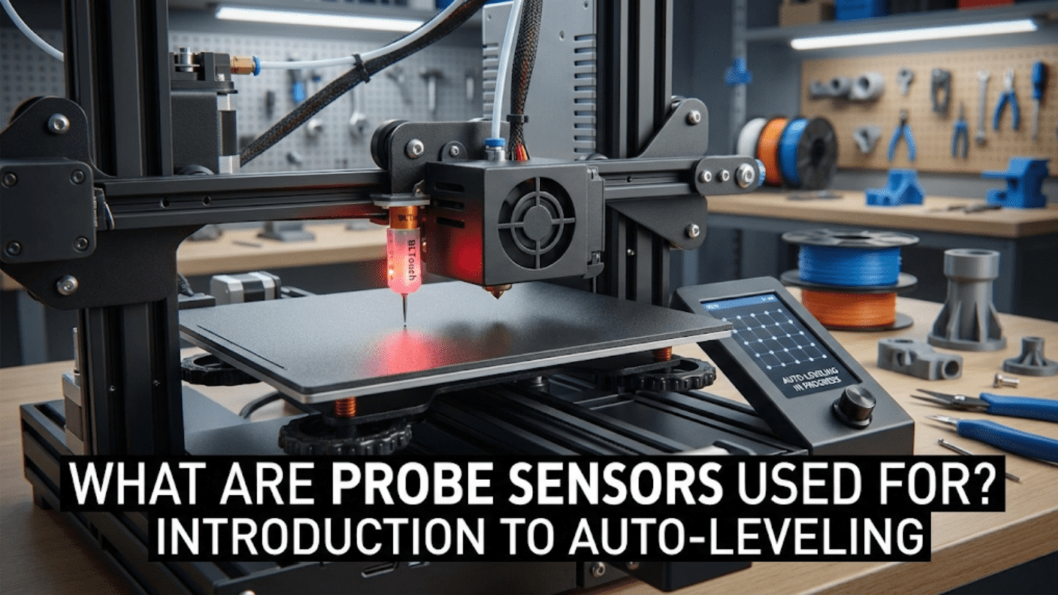
Probe sensors enable automatic bed leveling by detecting the bed surface at multiple points across the build area, creating a height map (mesh) that the firmware uses to compensate for bed irregularities during printing. Common probe types include BLTouch (deployable pin touching the surface), inductive probes (detecting metal beds electromagnetically), capacitive probes (sensing surface proximity), and mechanical touch probes, all serving to eliminate tedious manual bed leveling by automatically measuring and compensating for bed tilt, warping, or height variations.
Introduction
Anyone who has spent time manually leveling a 3D printer bed knows the frustration. You adjust the front-left corner, check front-right, adjust rear-left, return to front-left to find it’s now off again. After multiple iterations, you achieve acceptable leveling, only to find it drifts over time or varies with temperature. The process is tedious, time-consuming, and never quite perfect.
Automatic bed leveling eliminates this frustration by using probe sensors to measure the bed surface automatically. The printer probes multiple points across the bed, creating a detailed map of its actual position in 3D space. The firmware then compensates for any tilt or warping by dynamically adjusting the nozzle height during printing. What was imperfectly flat becomes virtually perfect through software compensation.
Yet probe sensors and auto-leveling systems vary enormously. Simple probes measure just a few points. Sophisticated systems create detailed meshes with dozens of measurements. Some probes work with any surface while others require specific bed materials. Understanding these differences helps you evaluate what your printer offers, decide if upgrading makes sense, and configure the system optimally.
In this comprehensive guide, we’ll explore what probe sensors do, examine different probe technologies, understand how auto-leveling works, and learn to configure and troubleshoot these helpful systems.
What Bed Leveling Probes Do
Before examining specific probe types, understanding their function reveals their value:
The Bed Leveling Problem
Even with careful manual adjustment, beds are never perfectly level:
Manufacturing Tolerances:
- Aluminum beds aren’t perfectly flat (±0.1-0.3mm common)
- Mounting surfaces have irregularities
- Frame components have slight variations
- Assembly introduces additional variance
Thermal Effects:
- Heating causes expansion and warping
- Different areas heat at different rates
- Repeated heating cycles can cause permanent warping
- Thermal stress can shift mounting
Mechanical Shifts:
- Bed movement during printing
- Leveling screw loosening over time
- Frame flex under load
- Bearing wear creating play
The Result: A bed that’s rarely flat within the 0.05-0.1mm tolerance first layers demand.
How Probes Solve This
Probes automate bed measurement:
Probing Sequence:
- Printer homes all axes to establish coordinate system
- Probe deploys (if retractable type)
- Printer moves to first probe point
- Z-axis lowers until probe triggers
- Firmware records Z-height at this XY location
- Probe retracts (if applicable)
- Moves to next point, repeats
- After all points probed, creates height map
Mesh Creation:
- Multiple probe points create a grid of height measurements
- Firmware interpolates between points
- Creates continuous height map across bed
- Stores mesh for use during printing
Compensation During Printing:
- As print head moves to different XY locations
- Firmware looks up mesh height for that position
- Adjusts Z-height dynamically
- Nozzle maintains constant distance from actual bed surface
- Compensates for tilt and warping automatically
Probe Sensor Types
Several technologies detect bed surface position:
BLTouch and Clone Probes
The most popular probe type uses a deployable pin:
Mechanism:
- Servo motor deploys/retracts a metal pin
- Pin extends below nozzle when probing
- Pin physically contacts bed surface
- Optical sensor detects when pin pushed up slightly
- Triggers signal sent to mainboard
- Servo retracts pin after measurement
Advantages:
- Works with any bed surface material
- Very accurate (±0.005mm repeatability claimed)
- Proven, well-supported technology
- Self-testing capability detects probe failures
- Wide temperature operating range
Disadvantages:
- Mechanical complexity (servo, pin mechanism)
- More expensive than simple probes ($30-50)
- Slower probing (deployment/retraction takes time)
- Mechanical parts can fail
- Requires careful mounting and wiring
Installation:
- Mounts beside hotend
- Must be lower than nozzle when deployed
- Higher than nozzle when retracted
- 5-wire connection to mainboard
- Firmware configuration for servo control
Maintenance:
- Verify pin deploys/retracts smoothly
- Clean pin contact surface
- Check mounting security
- Test self-test function periodically
Inductive Proximity Probes
Metal-detecting probes use electromagnetic sensing:
Operation Principle:
- Generates electromagnetic field
- Metal entering field changes field properties
- Electronics detect this change
- Triggers at specific distance from metal
Metal Surface Requirement:
- Only detects metal (aluminum, steel, etc.)
- Does not detect glass, PEI, or BuildTak directly
- Users sometimes add metal squares at probe points
- Or probe aluminum bed through non-metal surface
Advantages:
- No moving parts (solid-state)
- Very reliable and durable
- Inexpensive ($10-25)
- Fast probing (instant trigger)
- No deployment/retraction delay
Disadvantages:
- Requires metal surface or targets
- Sensing distance varies with bed material
- Temperature affects sensing distance
- Different metals trigger at different distances
- May require offset calibration
Types:
- NPN: Output low when triggered (less common)
- PNP: Output high when triggered (more common)
- Must match mainboard input type
Sensitivity Range:
- Typically 2-4mm sensing distance
- Adjustable on some models (potentiometer)
- Must calibrate Z-offset for nozzle-to-bed distance
Capacitive Proximity Probes
These detect surface proximity through capacitance changes:
Operation:
- Creates small electric field
- Any material approaching changes capacitance
- Electronics measure capacitance change
- Triggers at specific distance
Advantages:
- Detects any surface material (metal, glass, plastic)
- No moving parts
- Reliable solid-state operation
- Relatively inexpensive ($15-30)
- Fast probing
Disadvantages:
- Sensitivity affected by surface material
- Moisture can affect readings
- Temperature sensitivity
- May need recalibration for different surfaces
- Less common (less community support)
Adjustment:
- Potentiometer adjusts trigger distance
- Calibration needed for specific bed
- May require recalibration if changing surfaces
Mechanical Touch Probes
Simple switches detect contact:
Design:
- Microswitch or similar contact sensor
- Probe tip extends below nozzle
- Contacts bed, triggers switch
- Very simple, low-cost approach
Advantages:
- Extremely simple and cheap ($5-15)
- Works with any surface
- Easy to understand and repair
- No complex electronics
Disadvantages:
- Less accurate than other types
- Mechanical wear over time
- Slower than solid-state probes
- Can scratch delicate surfaces
- Often DIY/custom implementations
Applications:
- Budget builds
- Learning/experimentation
- Simple auto-leveling implementations
Probe Sensor Comparison Table
| Probe Type | Cost | Surface Compatibility | Accuracy | Speed | Reliability | Complexity | Best For |
|---|---|---|---|---|---|---|---|
| BLTouch | $$$ | Any | Excellent | Moderate | Good | Medium | General use, proven solution |
| Clone BLTouch | $$ | Any | Good | Moderate | Variable | Medium | Budget BLTouch alternative |
| Inductive | $$ | Metal only | Good | Fast | Excellent | Low | Metal beds, durability |
| Capacitive | $$ | Any | Moderate | Fast | Good | Low | Any surface, simplicity |
| Mechanical Touch | $ | Any | Moderate | Slow | Moderate | Very Low | Budget, learning |
How Auto-Leveling Works
Understanding the complete process reveals how probes enable compensation:
Probing Grid Configuration
Grid Size: Firmware defines probe point pattern:
- 3×3 grid (9 points): Basic coverage
- 4×4 grid (16 points): Better detail
- 5×5 grid (25 points): Good detail for most beds
- 7×7 or larger: Very detailed mesh for large/warped beds
Point Distribution:
- Evenly spaced across printable area
- May avoid unmountable areas (bed clips, etc.)
- Denser grids capture more detail but take longer
- Balancing detail vs. probing time
Boundary Limits:
- Probe points must be reachable
- Account for probe offset from nozzle
- Stay within printable bounds
- Avoid collisions with bed hardware
Mesh Bed Leveling Process
Step-by-Step:
- Home: All axes home to establish reference
- Heat: Bed heats to printing temperature (thermal expansion)
- Deploy: Probe deploys if retractable type
- First Point: Move to first probe location
- Probe: Lower Z until trigger, record height
- Next Point: Move to next location, repeat
- Complete Grid: Probe all defined points
- Calculate Mesh: Firmware creates interpolated height map
- Store: Mesh saved to memory (RAM or EEPROM)
- Ready: Printer ready to print with compensation
Timing:
- 3×3 grid: ~1-2 minutes
- 5×5 grid: ~3-5 minutes
- Larger grids: proportionally longer
Compensation During Printing
Dynamic Z Adjustment:
- Firmware knows current XY position during printing
- Looks up mesh height for that position
- Applies Z-offset to maintain constant nozzle-bed distance
- Updates continuously as head moves
Interpolation:
- Between probe points, heights are interpolated
- Bilinear interpolation common (smooth transition)
- More probe points = more accurate interpolation
Limitations:
- Cannot fix extreme warping (>2-3mm)
- First layer adhesion still requires reasonably flat bed
- Probe accuracy limits compensation precision
- Very localized defects between probe points may not compensate well
Probe Offset Configuration
Critical to accurate probing:
X and Y Offset
Physical Offset: Probe mounts beside nozzle, not at same location:
- Measure horizontal distance from nozzle tip to probe trigger point
- X-offset: Left (-) or right (+) of nozzle
- Y-offset: Front (-) or rear (+) of nozzle
- Firmware uses these to compensate during probing
Measurement:
- Mark probe trigger position on bed
- Home printer, note nozzle position
- Measure distances
- Configure in firmware (mm)
Z Offset
Trigger Height: Probe triggers at different height than nozzle touches bed:
- Distance between probe trigger and nozzle tip
- Usually negative value (probe triggers before nozzle reaches bed)
- Critical for first layer height
Calibration Process:
- Run probe sequence to establish reference
- Disable steppers, manually position paper under nozzle
- Adjust Z until proper paper drag
- Note Z-position difference from probe reference
- Set as Z-offset in firmware
- Fine-tune during first layer of test print
Live Adjustment: Many firmwares allow Z-offset adjustment during first layer (babystepping).
Firmware Configuration
Probes require proper firmware setup:
Marlin Configuration
Enable Probing:
#define AUTO_BED_LEVELING_BILINEAR  // or UBL, LINEAR, 3POINT
#define Z_MIN_PROBE_USES_Z_MIN_ENDSTOP_PIN // or dedicated pinProbe Type:
#define BLTOUCH // or FIX_MOUNTED_PROBE, etc.Offsets:
#define NOZZLE_TO_PROBE_OFFSET { -45, -10, -2.5 } // X, Y, ZGrid Configuration:
#define GRID_MAX_POINTS_X 5
#define GRID_MAX_POINTS_Y 5Probe Speeds:
#define Z_PROBE_SPEED_FAST 8  // mm/s
#define Z_PROBE_SPEED_SLOW 4 // mm/sKlipper Configuration
Probe Definition:
[bltouch]
sensor_pin: ^P0.10
control_pin: P2.0
x_offset: -45.0
y_offset: -10.0
z_offset: 2.5Mesh Configuration:
[bed_mesh]
speed: 120
mesh_min: 20, 20
mesh_max: 280, 280
probe_count: 5, 5Using Auto-Leveling Effectively
Getting the most from probe systems:
When to Run Probing
Before Every Print (recommended):
- Bed position can shift between prints
- Temperature changes affect bed geometry
- Only adds 1-5 minutes to print start
- Ensures compensation matches current state
Periodic Updates:
- Some users probe less frequently
- Store mesh, reuse for multiple prints
- Re-probe if first layer problems develop
- Re-probe after bed adjustments or changes
After Events:
- Changing bed surface
- Moving printer
- Significant temperature environment changes
- Any mechanical adjustments to bed
Optimizing Probe Points
Dense vs. Sparse:
- More points = better detail but slower probing
- Start with 5×5, adjust based on results
- Heavily warped beds benefit from denser meshes
- Flat beds work fine with 3×3 or 4×4
Point Placement:
- Ensure even coverage of used print area
- If printing primarily in bed center, focus points there
- Avoid probe points on bed clips or hardware
- Test probe points reachable before starting print
Verifying Compensation
First Layer Observation:
- Watch first layer carefully
- Should show consistent squish across entire area
- Inconsistency indicates probe issues or extreme warping
Test Prints:
- Large first layer test (covering most bed area)
- Should adhere uniformly everywhere
- Thickness should appear consistent
- Gaps or over-squishing indicate problems
Common Probe Problems
Probe Not Triggering
Symptoms: Z-axis crashes into bed, probe never signals.
Causes:
- Probe not deploying (BLTouch)
- Wrong trigger logic in firmware
- Disconnected wiring
- Probe failure
- Out of sensing range (inductive/capacitive)
Solutions:
- Verify probe deployment
- Check firmware trigger configuration
- Test wiring continuity
- Replace failed probe
- Adjust sensing distance
Inconsistent Probing
Symptoms: Probe points vary significantly on repeated measurements.
Causes:
- Mechanical instability (loose mounting)
- Temperature affecting probe
- Surface contamination
- Electromagnetic interference
- Insufficient probe speed (too fast)
Solutions:
- Secure probe mounting firmly
- Allow thermal stabilization before probing
- Clean bed surface
- Improve wiring shielding
- Reduce probe speed in firmware
Incorrect Z-Offset
Symptoms: First layer too high or too low despite probing.
Causes:
- Z-offset not calibrated correctly
- Probe offset misconfigured
- Nozzle height changed (nozzle replacement)
Solutions:
- Recalibrate Z-offset carefully
- Verify probe offsets in firmware
- Adjust offset after nozzle changes
- Use babystepping during first layer to fine-tune
Mesh Not Applied
Symptoms: Probing completes but compensation doesn’t work.
Causes:
- Compensation not enabled in start G-code
- Mesh not loaded from storage
- Firmware bed leveling disabled
Solutions:
- Add
M420 S1after G28 in start G-code (Marlin) - Verify mesh loaded:
M420 Vreports mesh status - Check firmware auto-leveling enabled
Advanced Probing Techniques
Unified Bed Leveling (UBL)
Marlin’s advanced system:
Features:
- Combines probing with manual adjustment
- Stores multiple mesh profiles
- Mesh editing capabilities
- Very detailed compensation possible
Workflow:
- Automatic probe creates base mesh
- Manual point additions refine mesh
- Mesh validated and edited as needed
- Saved profiles for different conditions
Mesh Visualization
Tools:
- OctoPrint plugins display mesh graphically
- Shows bed topology visually
- Identifies warping patterns
- Helps diagnose bed issues
Benefits:
- Visual confirmation of mesh quality
- Easy identification of problem areas
- Verification of probe accuracy
Automatic Tilt Adjustment
Some systems combine probing with motorized adjustment:
Operation:
- Probe measures bed tilt
- Motors automatically adjust leveling screws
- Physically levels bed rather than just compensating
- Results in both mechanical level and mesh compensation
Conclusion
Probe sensors and automatic bed leveling transform one of 3D printing’s most frustrating tasks—manual bed leveling—into an automated process requiring minimal user intervention. Whether using a sophisticated BLTouch with its deployable pin, a simple inductive probe detecting metal surfaces, or a capacitive sensor working with any material, the principle remains the same: measure the bed surface automatically, create a compensation mesh, and maintain constant nozzle-to-bed distance regardless of bed irregularities.
Understanding what probes do—creating detailed height maps through systematic measurement—and how they work with firmware to provide dynamic Z-compensation during printing reveals why they’ve become standard features on quality printers. The small time investment probing before each print pays enormous dividends in reliability, eliminating first layer failures from bed leveling issues.
Proper configuration, including accurate probe offset calibration and appropriate mesh density, ensures probes work effectively. Regular verification that compensation applies correctly and first layers show uniform adhesion confirms the system functions as intended. When problems arise, understanding common failure modes—inconsistent triggering, incorrect offsets, mesh not applied—enables quick diagnosis and resolution.
The next time you start a print and watch your printer automatically probe the bed, creating an invisible height map in memory, appreciate the technology making it possible. Those few minutes of systematic measurement eliminate hours of manual leveling frustration while providing better results than manual adjustment could achieve, ensuring every print starts on a solid foundation regardless of bed imperfections.