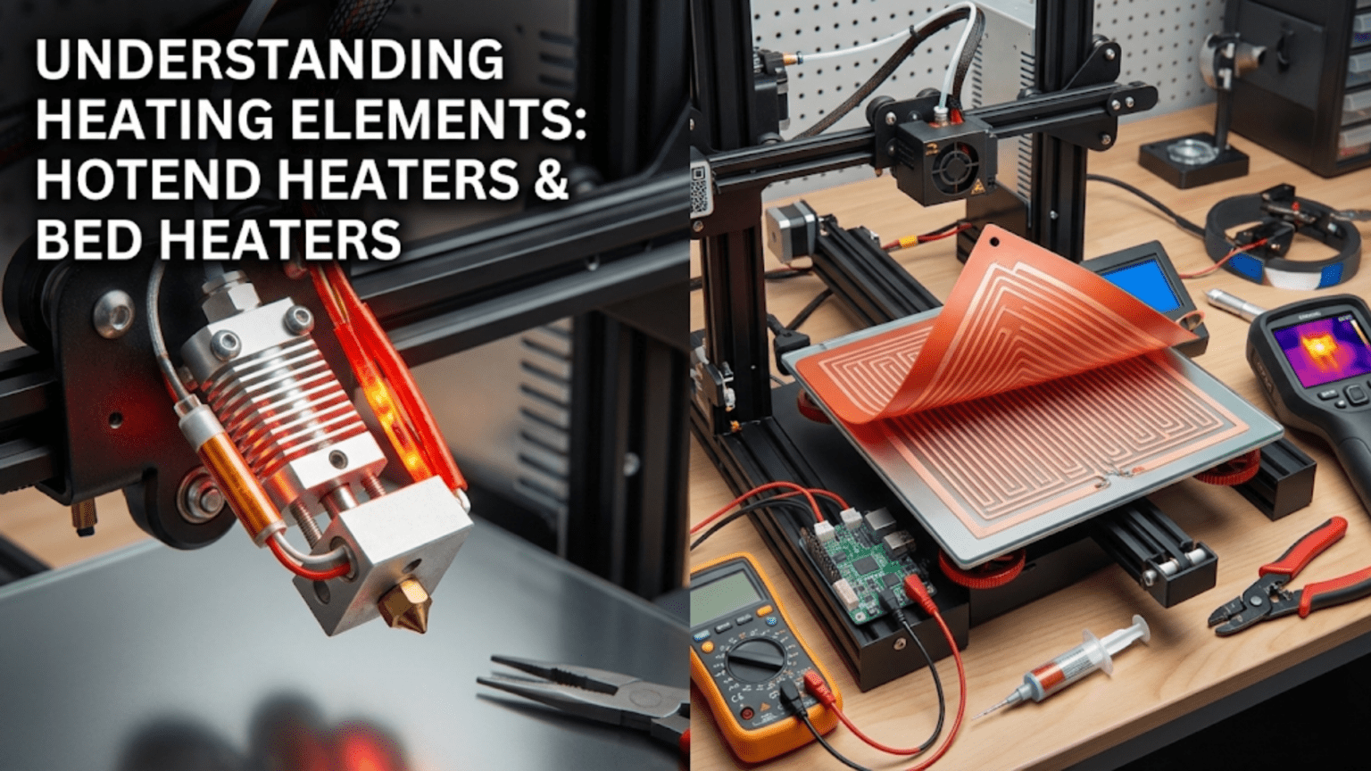
Heating elements in 3D printers convert electrical energy into thermal energy through resistive heating, with hotend cartridge heaters (typically 40-60 watt cylindrical metal tubes containing resistive wire) melting filament in the melt zone, while heated bed elements (either PCB trace heaters or silicone mat heaters ranging from 100-500+ watts) warm the build surface to improve adhesion and reduce warping. Both types work on the principle of electrical resistance generating heat (joule heating), controlled by the mainboard through PWM signals and regulated by PID algorithms based on thermistor feedback to maintain precise target temperatures essential for quality printing.
Introduction
At the heart of every successful 3D print lies controlled heating. Plastic filament must reach precise temperatures to melt into flowing material that can be deposited layer by layer. The build surface must maintain warmth to prevent warping and ensure adhesion. Without heating elements transforming electrical power into thermal energy at exactly the right places and times, 3D printing as we know it couldn’t exist.
Yet these heating components work invisibly, hidden inside hotends and beneath build plates. Most users never see the actual heater cartridge or the PCB traces generating warmth. They interact only with temperature settings in software, unaware of the sophisticated thermal systems making those numbers real.
Understanding heating elements—how they generate heat, why power ratings matter, what differentiates hotend and bed heaters, and how to troubleshoot problems—demystifies a critical aspect of printer operation. You’ll recognize why a 40-watt heater cartridge differs from a 60-watt version, understand what limits heated bed performance, and learn to diagnose heating problems before they ruin prints or damage equipment.
In this comprehensive guide, we’ll explore both hotend and heated bed heating elements, examining their construction, operation principles, power requirements, and maintenance needs. By the end, you’ll understand the thermal foundation enabling the plastic transformation that creates your printed objects.
The Physics of Resistive Heating
All 3D printer heating elements work on the same fundamental principle:
Joule Heating (Resistive Heating)
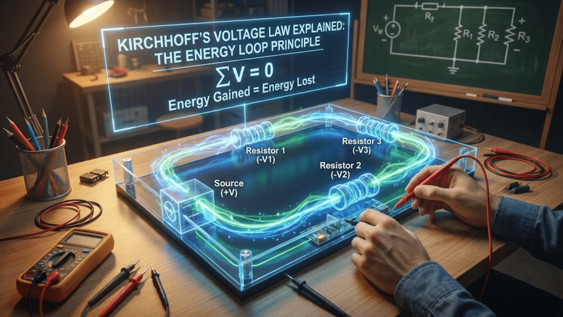
When electrical current flows through a conductor with resistance, energy dissipates as heat:
The Formula: P = I²R or P = V²/R
Where:
- P = Power (watts)
- I = Current (amperes)
- R = Resistance (ohms)
- V = Voltage (volts)
Physical Process: Electrons flowing through the resistive material collide with atoms, transferring kinetic energy that manifests as heat. Higher resistance or higher current creates more collisions, generating more heat.
Intentional Resistance: Unlike normal wiring where we minimize resistance, heating elements deliberately use high-resistance wire or materials to convert maximum electrical energy into heat.
Temperature Control Through Power Modulation
The mainboard controls heating by varying the power supplied:
PWM (Pulse Width Modulation): Rather than varying voltage, the controller rapidly switches power fully on and off:
- 100% duty cycle (always on) = maximum heating
- 50% duty cycle (on half the time) = half power
- 0% duty cycle (always off) = no heating
Frequency: PWM typically operates at 10-30 Hz, fast enough that thermal mass smooths the pulsed power into steady heating.
PID Control: The firmware uses PID (Proportional-Integral-Derivative) algorithms to calculate the appropriate PWM duty cycle based on temperature sensor feedback, maintaining stable temperatures within a few degrees of target.
Heat Transfer Modes
Generated heat transfers to the target (plastic or build plate):
Conduction: Direct contact transfer—the dominant mode in both hotend and bed heating. The heater element touches the heater block or bed surface, conducting heat directly.
Convection: Air movement transfers heat. This is minimized in heating design (we want heat going into components, not air) but factors into cooling and heat loss.
Radiation: Electromagnetic radiation carries heat. At typical printing temperatures, this represents minimal heat transfer but becomes more significant at very high temperatures.
Hotend Cartridge Heaters
The standard hotend heating element is a compact cartridge heater:
Construction and Design
Physical Form: A cylindrical metal tube, typically:
- 6mm diameter × 20mm length (most common)
- Other sizes exist (8mm, 10mm diameter; various lengths)
- Standardized dimensions allow interchangeability
Internal Components:
- Resistive wire: High-resistance alloy wire (nichrome or similar) coiled inside the cartridge
- Ceramic insulation: Surrounds the wire, providing electrical isolation while allowing heat transfer
- Metal sheath: Stainless steel or similar alloy protects internal components and provides structural integrity
- Lead wires: Two wires exit one end, connecting to the mainboard’s heater output
Sealing: The open end where wires exit is sealed to prevent moisture and contamination from entering the cartridge.
Power Ratings
Cartridge heaters come in various wattages:
Common Ratings:
- 30 watts: Lower power, adequate for standard printing at moderate speeds
- 40 watts: Most common, balances performance with electrical requirements
- 50 watts: Higher performance for faster printing or larger hotends
- 60 watts: High-flow applications, rapid printing
Voltage Options:
- 12V versions for 12V printer systems
- 24V versions for 24V systems
- Must match printer voltage—using wrong voltage causes severe under or overheating
Current Draw:
- 40W at 12V = 3.33 amps
- 40W at 24V = 1.67 amps
- 60W at 12V = 5 amps
- 60W at 24V = 2.5 amps
The 24V advantage: half the current for the same power, allowing smaller wire gauges and reducing voltage drop.
Installation and Mounting
Heater Block Bore: The cartridge inserts into a precision-drilled hole in the aluminum heater block:
- 6mm bore for standard 6mm cartridges
- Tight tolerance (6.0-6.1mm) ensures good thermal contact
- Length ensures cartridge seats fully without protruding
Thermal Contact: Critical for efficiency:
- Clean bore before installation
- Apply thermal paste to fill microscopic air gaps
- Push cartridge fully into bore
- Some designs use thermal pads for easier installation
Retention: A set screw secures the cartridge:
- Tighten when heater block is at temperature (thermal expansion ensures proper fit)
- Adequate tightness prevents cartridge from sliding out
- Excessive force can crack ceramic insulation inside cartridge
Wire Routing: The heater wires require careful management:
- Strain relief prevents wire breakage
- High-temperature insulation near heater block
- Route away from moving parts
- Secure without creating tension
Performance Characteristics
Heat-Up Time: How quickly the hotend reaches temperature:
- 30W heater: 2-3 minutes to 200°C
- 40W heater: 1.5-2 minutes to 200°C
- 60W heater: 1-1.5 minutes to 200°C
- Times vary with heater block mass and ambient temperature
Temperature Recovery: How quickly temperature recovers during high-flow printing:
- Melting plastic constantly removes heat
- Higher wattage maintains temperature better during rapid extrusion
- Insufficient wattage causes temperature drop during fast printing
Maximum Temperature: Quality cartridge heaters typically handle:
- Continuous operation to 300°C+
- Brief excursions to 350°C+
- Higher-temperature applications may need specialized heaters
Common Problems and Solutions
Heater Failure:
- Symptom: Temperature won’t rise despite heater activation
- Cause: Broken internal wire, open circuit
- Diagnosis: Measure resistance (should be V²/P, e.g., 12²/40 = 3.6 ohms for 40W 12V heater)
- Solution: Replace heater cartridge
Weak Heating:
- Symptom: Slow heat-up, temperature drops during printing
- Cause: Wrong voltage heater, failing heater, poor thermal contact
- Diagnosis: Verify voltage rating matches system, check resistance
- Solution: Replace with correct heater, improve thermal paste application
Intermittent Operation:
- Symptom: Temperature fluctuates, occasional drops or spikes
- Cause: Loose connections, damaged wires, poor contact
- Diagnosis: Wiggle wires while watching temperature
- Solution: Secure connections, replace damaged wires
Thermal Runaway Errors:
- Symptom: Firmware triggers thermal runaway protection
- Cause: Thermistor failure (not heater), heater undersized, poor PID tuning
- Diagnosis: Verify thermistor function, check heater rating
- Solution: Fix thermistor, upgrade heater if undersized, tune PID
Heated Bed Elements
Heated beds use larger, distributed heating elements:
PCB Trace Heaters
Many heated beds use PCB technology:
Construction:
- Printed circuit board with copper traces forming resistive heating elements
- Traces routed in serpentine or grid patterns across bed area
- Multiple layers sometimes used for higher power density
- Solder mask coating protects traces
Trace Design:
- Carefully calculated width and spacing to achieve target resistance
- Patterns designed for even heat distribution
- Wider traces at edges compensate for greater heat loss
- Multiple parallel paths for reliability
Power Distribution:
- Heavy copper traces carry input power to distributed heating traces
- Terminals or solder pads connect to power supply
- Some designs include integrated thermistor mounting
Advantages:
- Integrated design (heater and structural base in one)
- Good heat distribution with proper design
- Relatively thin profile
- Cost-effective for mass production
Disadvantages:
- Difficult to repair if traces fail
- Power limited by PCB thermal capacity
- May not achieve high temperatures (typically max 120-130°C)
- Quality varies significantly between manufacturers
Silicone Mat Heaters
Flexible silicone heating mats offer alternative construction:
Design:
- Resistive wire embedded in silicone rubber material
- Typically 2-4mm thickness
- Wire routed in patterns for even heating
- Adhesive backing allows attachment to aluminum beds
Construction Options:
- Etched foil: Similar to PCB but on flexible substrate
- Wire elements: Actual resistance wire embedded in silicone
- Hybrid designs combining technologies
Installation:
- Adhesive backing sticks to bottom of aluminum build plate
- Some use mechanical attachment with clips
- Thermal adhesive improves heat transfer
- Insulation foam beneath reduces heat loss downward
Advantages:
- Higher power density possible (500W+ on large beds)
- Can reach higher temperatures (150°C+)
- Separable from bed plate (easier replacement)
- Flexible, conforming to slight bed irregularities
Disadvantages:
- More expensive than PCB heaters
- Requires separate aluminum build plate
- Installation more complex
- Can delaminate if adhesive fails
Heated Bed Power Requirements
Bed heating demands substantial power:
Power Scaling with Size:
- Small bed (200×200mm): 100-150W typical
- Medium bed (250×250mm): 200-250W typical
- Large bed (300×300mm): 300-400W typical
- Extra-large beds: 500-750W or more
Heat Loss Factors:
- Surface area determines total heat loss
- Larger beds lose more heat, need more power
- Insulation significantly improves efficiency
- Ambient temperature affects requirements
Target Temperatures by Material:
- PLA: 50-60°C (lower power demand)
- PETG: 70-80°C (moderate power)
- ABS: 90-110°C (higher power required)
- High-temp materials: 120-150°C (maximum power)
Heat-Up Time Considerations:
- Users prefer quick heat-up (2-5 minutes)
- Faster heating requires higher wattage
- Thermal mass of aluminum bed affects time
- Insulation speeds heat-up by reducing losses
Heated Bed Comparison Table
| Heater Type | Typical Power | Max Temp | Cost | Installation | Replaceability | Heat Distribution |
|---|---|---|---|---|---|---|
| PCB Integrated | 100-200W | 110-130°C | $ | Easy (comes as unit) | Difficult | Good with quality design |
| PCB Separate | 100-200W | 110-130°C | $ | Moderate | Moderate | Good with quality design |
| Silicone Mat Standard | 200-400W | 150°C+ | $$ | Moderate (adhesion) | Easy | Very good |
| Silicone Mat High-Power | 400-750W+ | 150°C+ | $$$ | Moderate (heavy wiring) | Easy | Excellent |
| AC Mains (120/240V) | 500-1000W+ | 150°C+ | $$$ | Complex (dangerous) | Moderate | Excellent with design |
Heating Element Wiring and Electrical Safety
Proper wiring ensures safe, reliable operation:
Wire Gauge Requirements
Current-carrying capacity determines required wire size:
Hotend Heater (40W example):
- 12V system: 3.33A → 18-20 AWG minimum
- 24V system: 1.67A → 20-22 AWG adequate
Heated Bed (200W example):
- 12V system: 16.7A → 14-16 AWG required
- 24V system: 8.3A → 18-20 AWG adequate
Undersized Wires: Create multiple problems:
- Excessive voltage drop reduces delivered power
- Wire overheating (fire hazard)
- Poor temperature control
- Accelerated wire insulation degradation
Safety Margin: Use wire rated for 25% more current than expected maximum draw.
Connection Methods
Screw Terminals: Most common for bed heaters:
- Properly sized for wire gauge
- Tightened adequately (without stripping)
- Use ferrules on stranded wire for reliable contact
- Check periodically—thermal cycling can loosen connections
Crimp Connectors: Common for hotend heaters:
- Quality crimps ensure reliable connection
- Heat-resistant connectors near heater block
- Proper crimp tools essential (avoid pliers)
- Verify crimp integrity by pull-testing
Solder Connections: Sometimes used but challenging:
- High-current connections require substantial solder
- Heat cycles can degrade solder joints
- Not recommended for bed heater power connections
- Acceptable for low-current heater control signals
Insulation and Protection
High-Temperature Insulation: Near heaters:
- Silicone rubber insulation rated for temperature
- PTFE (Teflon) insulation for extreme heat
- Fiberglass sleeving for additional protection
- Keep insulation in good condition
Strain Relief:
- Prevents wire breakage from flexing
- Critical at heater connections
- Cable chains for moving bed wiring
- Secure routing prevents snagging
MOSFET and Relay Control
The mainboard typically uses MOSFETs or relays to control heaters:
MOSFET (Metal-Oxide-Semiconductor Field-Effect Transistor):
- Solid-state switch controlling heater power
- Fast switching for PWM control
- Common in modern boards for both hotend and bed
- Can fail if undersized for current
- Electromechanical switch
- Used for very high-current bed heaters
- Audible clicking during operation
- Limited switching speed (not ideal for fast PWM)
External MOSFET Modules:
- Recommended for high-power heated beds
- Protects mainboard from high current
- Dedicated heatsinking for reliability
- Simple wiring: signal from board, power to heater
Heating Element Maintenance
Regular maintenance ensures reliable operation:
Inspection Schedule
Monthly:
- Visual inspection of wiring condition
- Check connection tightness (when cool)
- Listen for unusual sounds (clicking relays, arcing)
- Verify proper heat-up times haven’t increased
Quarterly:
- Resistance measurement of heaters
- Detailed wire inspection for damage
- Verify insulation integrity
- Check strain relief effectiveness
Annually:
- Consider preventive replacement of hotend heater (cheap insurance)
- Deep inspection of bed heater adhesion
- Verify all electrical connections
- Test ground continuity if applicable
Resistance Testing
Verifying heater resistance ensures proper function:
Expected Resistance: Calculate using R = V²/P
- 40W, 12V heater: 144/40 = 3.6 ohms
- 40W, 24V heater: 576/40 = 14.4 ohms
- 200W, 12V bed: 144/200 = 0.72 ohms
- 200W, 24V bed: 576/200 = 2.88 ohms
Testing Procedure:
- Disconnect heater from power
- Measure resistance across heater terminals with multimeter
- Compare to calculated expected value
- ±10% is typically acceptable
- Open circuit (infinite resistance) = broken heater
- Very low resistance = short circuit
Temperature Coefficient: Resistance increases slightly with temperature, so cold measurements may read slightly lower than calculated values.
Cleaning and Care
Hotend Heater:
- Keep heater block clean (plastic buildup insulates)
- Don’t get thermal paste on wires
- Avoid mechanical shock to cartridge
- Replace when resistance drifts significantly
Heated Bed:
- Clean build surface regularly (protects heater underneath)
- Check adhesive condition on silicone mats
- Ensure insulation remains in place below heater
- Keep area around wiring connections clean
Upgrading Heating Elements
Consider upgrades for improved performance:
Higher Wattage Hotend Heaters
When to Upgrade:
- Frequent temperature drops during fast printing
- Desire for very high print speeds
- Using large nozzles (0.8mm+) or Volcano hotends
- Printing high-temperature materials
Considerations:
- Verify mainboard can handle increased current
- May need external MOSFET if current exceeds board rating
- Confirm power supply capacity
- Higher wattage enables faster heat-up and recovery
Bed Heater Replacement
Upgrade Reasons:
- Inadequate temperature or slow heating
- Failed existing heater
- Upgrading bed size
- Adding heat where none existed
Silicone Mat Advantages:
- Easier replacement than integrated PCB
- Higher power capability
- Better temperature distribution
- Flexibility in mounting
Installation Tips:
- Clean bed surface thoroughly before adhesive application
- Apply evenly without bubbles or wrinkles
- Secure wiring safely
- Add insulation below for efficiency
Bed Insulation
Often-overlooked upgrade with significant impact:
Materials:
- Cork sheet (cheap, effective)
- Ceramic fiber insulation (excellent thermal resistance)
- Foil-faced foam (reflects heat)
- Commercial bed insulation kits
Benefits:
- Faster heat-up times
- Reduced power consumption
- More stable temperature
- Less heat affecting electronics below
Installation:
- Attach to bottom of bed or heater
- Don’t block mounting hardware
- Thickness vs Z-axis clearance tradeoff
- Secure so it doesn’t shift
Safety Considerations
Heating elements involve safety concerns:
Fire Risk
Prevention:
- Use proper wire gauge for current
- Ensure tight connections
- Verify insulation integrity
- Don’t exceed heater temperature ratings
- Keep flammable materials away from printer
Thermal Runaway Protection:
- Essential firmware safety feature
- Detects heating failures and runaways
- Shuts down heating if temperature doesn’t respond correctly
- Never disable this protection
Electrical Hazards
Voltage Safety:
- Low-voltage DC (12V/24V) is relatively safe
- Still requires proper insulation and connections
- Mains voltage AC bed heaters need extreme caution
- Ground metal components properly
Short Circuit Risk:
- Can cause fires or damage
- Fuses/breakers provide protection
- Quality PSUs include short circuit protection
- Regular inspection prevents problems
Burn Hazards
High Temperatures:
- Hotends reach 200-300°C+
- Heated beds reach 100-130°C+
- Both can cause serious burns
- Wait for cool-down before touching
- Use tools, not bare hands, for hot components
Conclusion
Heating elements transform electrical power into the thermal energy that makes 3D printing possible. The hotend’s cartridge heater melts solid filament into flowing plastic ready for deposition. The heated bed’s PCB traces or silicone mat create the warm surface that prevents warping and ensures reliable adhesion. These components work continuously throughout every print, controlled by sophisticated algorithms maintaining precise temperatures despite constantly changing thermal loads.
Understanding how heating elements work—the resistive heating principle converting electrical current into heat, the power ratings determining heating capability, the construction details affecting reliability and performance—demystifies this critical aspect of printer operation. You recognize why a 40-watt cartridge heater might struggle with high-speed printing while a 60-watt version performs flawlessly. You understand what limits heated bed performance and how insulation dramatically improves efficiency.
Proper installation using adequate wire gauges, secure connections, and appropriate strain relief ensures safe, reliable heating. Regular maintenance—inspecting wiring, testing resistance, verifying connections—prevents problems before they cause print failures or safety hazards. When upgrades become necessary, understanding power requirements and compatibility considerations enables informed decisions.
The next time you set a print temperature and watch it rise smoothly to your target, appreciate the heating elements making it happen. Those cartridge heaters and bed heating elements aren’t just resistive wires—they’re precision thermal tools converting electrical power into exactly the heat needed, in exactly the right places, at exactly the right times, enabling the plastic transformation that builds your designs into reality.