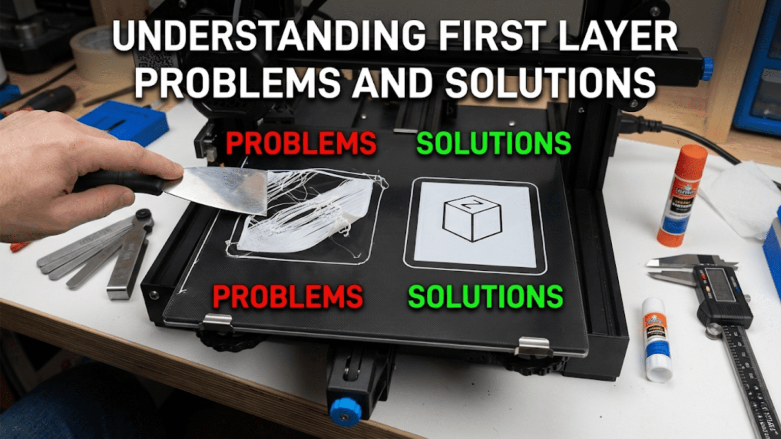
Introduction: Why the First Layer Makes or Breaks Everything
In 3D printing, there’s a saying that captures a fundamental truth: “Get the first layer right, and everything else will follow.” This isn’t hyperbole or oversimplification. The first layer of any print serves as the literal foundation for everything that comes after it, and if that foundation is flawed, the entire structure built upon it becomes compromised or fails entirely. A print can survive minor imperfections in later layers, slight variations in temperature, or occasional cooling issues, but a bad first layer almost always leads to complete print failure within minutes or hours.
The first layer’s critical importance stems from its unique role as the interface between the print and the physical world. Every subsequent layer bonds to the layer below it, plastic to plastic, with compatible materials and similar temperatures. But the first layer must bond to a fundamentally different surface, whether glass, PEI, textured powder coat, or another build surface, often at a different temperature and with different material properties. This interface presents challenges that don’t exist for any other layer in the print.
Beyond just sticking to the bed, the first layer establishes the geometric accuracy for the entire print. If the first layer is slightly too large, that error propagates upward. If corners of the first layer lift from the bed, those lifted corners create geometric distortions that affect every subsequent layer. If the first layer has gaps or inconsistencies in extrusion, those imperfections create weak points in the foundation that can cause failures later. The first layer literally sets the stage, and everything built upon that stage inherits its characteristics.
What makes first layer problems particularly frustrating for beginners is that they manifest in diverse ways with varying symptoms. Sometimes prints don’t stick at all, with the extruded plastic being dragged around by the nozzle instead of adhering to the bed. Sometimes they stick initially but lift partially through the print as stresses accumulate. Sometimes they stick too well, being difficult or impossible to remove without damaging the print or bed. Sometimes adhesion seems perfect but the print develops quality issues that trace back to first layer imperfections. Learning to read these different failure modes and understand their root causes is essential for moving beyond beginner struggles to consistent success.
The complexity of first layer troubleshooting comes from the number of variables involved. Bed leveling, nozzle height, bed temperature, nozzle temperature, print speed, cooling settings, bed surface condition, filament quality, ambient conditions, and even the model design all influence first layer success. A problem in any one of these areas can cause first layer failure, and sometimes multiple factors combine to create issues that single fixes can’t resolve. This interconnected web of causes means effective troubleshooting requires systematic thinking rather than random adjustment of settings hoping something works.
However, the good news is that first layer problems, while initially confusing, follow patterns. Certain symptoms reliably indicate specific causes, and understanding these cause-and-effect relationships transforms troubleshooting from frustrating guesswork into logical problem-solving. Once you’ve learned to recognize what different first layer problems look like and understand what causes them, fixing issues becomes much faster and more predictable. You develop the ability to glance at a failed first layer and immediately know whether the issue is leveling, temperature, adhesion, or something else entirely.
This article serves as your comprehensive guide to first layer mastery. We’ll explore the most common first layer problems in detail, examining what each looks like, what causes it, and most importantly, how to fix it. We’ll discuss the visual signatures that help you quickly diagnose issues, the systematic troubleshooting approaches that efficiently identify root causes, and the preventive measures that reduce first layer failures before they happen. Whether you’re a complete beginner fighting with your first prints or an intermediate user looking to refine your understanding and eliminate remaining issues, this deep dive into first layer problems and solutions will provide knowledge that immediately improves your printing success rate.
The Anatomy of a Perfect First Layer
Before diving into problems, understanding what a perfect first layer looks like provides the reference point against which you’ll compare problematic prints. Knowing what you’re aiming for makes it much easier to recognize when something is wrong and how far you are from the ideal. Let’s examine the characteristics of an excellent first layer in detail.
A perfect first layer has excellent bed adhesion across its entire surface. When you print the first layer and it cools, it should be firmly stuck to the bed without any lifting, curling, or loose edges. You shouldn’t be able to slide a fingernail under any part of the print to lift it. At the same time, the adhesion should be releasable when intended, strong enough to hold during printing but not so extreme that you risk damaging the print or bed surface during removal. This balance of secure yet releasable adhesion is what you’re seeking.
The visual appearance of the first layer provides immediate feedback about quality. Individual extrusion lines should be clearly visible but firmly pressed together with no gaps between adjacent lines. Each line appears slightly flattened and wider than the nozzle diameter due to the plastic being compressed against the bed. This spreading or “squish” is desirable and indicates proper nozzle height. The lines should have a consistent width throughout, not varying from thin to thick or showing gaps and over-extrusion in different areas.
The surface texture of the first layer reveals a lot about quality. With proper squish, the first layer should appear matte or slightly glossy rather than shiny. If individual lines are perfectly round in cross-section and sitting on top of the bed rather than pressed into it, you’re too high. If the lines are so compressed they become translucent or show tearing where excess plastic has been scraped away, you’re too close. The ideal falls between these extremes, with lines that are clearly flattened against the bed but maintain their integrity without being damaged.
The first layer’s thickness should be uniform across the entire print area. If you measure first layer height with calipers at different locations, the measurements should be consistent within a few hundredths of a millimeter. Significant variation indicates bed leveling issues where some areas are squished more than others. This uniformity extends to corners and edges, which are particularly prone to problems. Corners should adhere just as firmly as center regions without lifting or curling.
Looking at the first layer from the side after it’s complete reveals the layer’s profile. The height should match your first layer setting in the slicer, typically around two tenths to three tenths of a millimeter for standard prints. The layer should appear as a uniform thickness across its extent without sudden changes. If the layer appears wavy or uneven when viewed from the side, leveling or Z-axis problems may be present.
The transition from first layer to second layer should be smooth with the second layer bonding well to the first. While second layer issues often reflect cooling or temperature problems rather than first layer problems specifically, the first layer must provide a solid foundation that the second layer can adhere to reliably. If second layers consistently fail or show poor adhesion to the first layer, the first layer’s surface quality may be compromised even if it looks acceptable visually.
Corners and edges of the first layer deserve special attention because they’re most prone to problems. In a perfect first layer, corners remain flat and firmly adhered without any lifting or curling upward. The edges should be crisp and well-defined, following the intended geometry without rounding, warping, or pulling away from the bed. Any deviation from flat, firmly-stuck corners indicates developing problems that will likely worsen as the print continues.
The first layer’s bottom surface, the side that contacts the bed, should be smooth and consistent when you examine it after removing the print. The texture should match the bed surface texture, whether that’s mirror-smooth from glass, lightly textured from PEI, or heavily textured from powder-coated surfaces. You shouldn’t see areas where the plastic didn’t make full contact with the bed or areas with excessive compression creating thin spots. The bottom surface tells the story of how well the first layer process worked.
For large first layers covering significant bed area, warping resistance is part of perfection. A perfect large first layer remains flat and stuck even as it cools and internal stresses develop. Materials prone to warping like ABS present the ultimate test, where keeping large first layers adhered requires not just good bed adhesion but also appropriate temperature management and sometimes environmental control through enclosures. Success with challenging materials on large first layers represents mastery of first layer technique.
Understanding this ideal standard helps you evaluate your own first layers critically. When something goes wrong, you can compare what you’re seeing to this ideal and identify specific deviations that point toward particular problems. The gap between ideal and actual provides diagnostic information that guides your troubleshooting.
Problem: First Layer Not Sticking At All
The most dramatic and frustrating first layer problem is when the plastic simply refuses to stick to the bed, being dragged around by the moving nozzle in a growing ball of spaghetti instead of forming proper layers. This complete adhesion failure stops prints immediately and wastes material until you notice and cancel the print. Understanding the causes helps you address them systematically.
The most common cause of complete adhesion failure is incorrect nozzle-to-bed distance, specifically being too far away. When the nozzle is too high above the bed, the extruded plastic doesn’t get pressed onto the bed surface with enough force to create a bond. The plastic emerges from the nozzle, falls the gap distance to the bed without being compressed, and fails to stick because there’s no squish creating intimate contact. This is fundamentally a bed leveling issue where either the entire bed is too low or specific areas are too low.
Solving nozzle distance problems requires careful bed leveling as discussed in the previous article. If you’re experiencing non-sticking issues across the entire print area, the whole bed needs to be brought closer to the nozzle by adjusting your Z offset or leveling screws. If only certain areas won’t stick, those specific areas are too low and need raising. The paper drag method helps you find the correct distance where the nozzle is close enough for good squish without being so close it scrapes the bed.
Bed temperature being too low represents another frequent cause of adhesion failure. Every material has a temperature range where it adheres properly to bed surfaces. Print PLA at room temperature and adhesion is marginal at best. Print ABS at fifty degrees and it won’t stick reliably. If your bed temperature is below the appropriate range for your material, no amount of perfect leveling will create reliable adhesion. The solution is simply increasing bed temperature to the material’s recommended range, typically sixty to seventy degrees for PLA, eighty to ninety degrees for PETG, and one hundred to one hundred ten degrees for ABS.
However, excessive bed temperature can also cause issues. If the bed is significantly hotter than necessary, the plastic may not cool and solidify properly, remaining too soft and malleable to support subsequent layers. While this typically doesn’t cause complete adhesion failure, it can create other first layer problems. Stay within recommended temperature ranges rather than assuming hotter is always better.
Bed surface contamination is a common but often overlooked cause of adhesion failure. Fingerprint oils, dust, previous print residue, release agents accidentally applied, or general accumulated grime all prevent proper adhesion. Even if you had perfect adhesion yesterday, if you’ve touched the bed surface since then, those fingerprint oils can prevent today’s print from sticking. The solution is cleaning the bed thoroughly with isopropyl alcohol before each print, wiping in one direction rather than circular motions that can spread contamination.
Some materials and surfaces simply don’t adhere well to each other without intervention. Glass beds may not stick PLA reliably without some preparation like glue stick, hairspray, or upgrading to a textured surface. Fresh PEI sheets usually stick everything, but worn PEI may need refreshing with light sanding. Understanding material-surface compatibility helps you choose appropriate surfaces or apply necessary adhesion promoters.
Incorrect first layer settings in your slicer can prevent adhesion even when everything else is right. If your first layer speed is too fast, the plastic doesn’t have time to bond to the bed before the nozzle moves away. Typical first layer speeds should be around twenty to thirty millimeters per second or roughly half normal print speed. If first layer cooling is enabled too early or too aggressively, the plastic may cool too quickly and contract away from the bed. First layer cooling should generally be minimal or zero to maximize adhesion time.
Filament moisture contamination creates poor adhesion in hygroscopic materials like nylon, PETG, or even PLA in humid environments. Wet filament contains water that vaporizes during extrusion, creating tiny bubbles and surface irregularities that prevent good bed contact. If you’ve eliminated other causes and still can’t get adhesion, particularly with known hygroscopic materials, try thoroughly drying your filament before attempting to print.
Poor quality filament with inconsistent diameter or contamination can cause extrusion problems that manifest as adhesion failure. If the filament diameter varies significantly, the extruder may under-extrude on thin sections, depositing insufficient plastic to create proper bed contact. Trying a different, known-good filament helps diagnose whether the filament itself is problematic rather than your printer settings.
Problem: Warping and Corner Lifting
Warping, where corners or edges of the print lift away from the bed during printing, represents one of the most common and frustrating first layer problems. The print may start with perfect adhesion but gradually develop lifting as more layers are added and stresses accumulate. Understanding warping mechanisms helps you prevent and address this issue effectively.
The fundamental cause of warping is differential cooling and thermal contraction. As plastic cools from printing temperature to room temperature, it shrinks. Different parts of the print cool at different rates, with perimeters exposed to air cooling faster than interior sections surrounded by other plastic. This uneven cooling creates internal stresses as the faster-cooling sections try to shrink while still connected to slower-cooling sections. These stresses concentrate at corners and edges where the print attaches to the bed, and if stresses exceed adhesion strength, corners lift.
Materials differ dramatically in their warping tendency based on their thermal expansion coefficient and glass transition temperature. ABS is notoriously prone to warping because it shrinks significantly during cooling and has a high glass transition temperature. PLA is relatively warp-resistant thanks to low shrinkage and low glass transition temperature. PETG falls between these extremes. Understanding your material’s warping characteristics helps you implement appropriate countermeasures.
The most effective warping prevention is maintaining high bed temperature throughout the print, keeping the first layer warm and reducing thermal gradients between the bottom of the print and upper layers. For ABS, bed temperatures around one hundred to one hundred ten degrees are standard. Some users print ABS even hotter when warping is severe. Higher bed temperatures keep the bottom of the print at temperatures where the plastic remains compliant and internal stresses don’t build up as dramatically.
Enclosed printing environments dramatically reduce warping by keeping the entire print at elevated temperature rather than just the bottom. When the ambient air around the print is warm, perhaps forty to sixty degrees Celsius, the top surfaces don’t cool as rapidly and thermal gradients remain moderate. This is why serious ABS printing often requires enclosures. You can create effective enclosures using cardboard boxes, acrylic panels, or purpose-built enclosure kits. Even a simple enclosure significantly improves warping resistance.
Bed adhesion promoters like glue stick, hairspray, or specialized products increase adhesion strength, giving the bed a better chance of holding corners down despite warping forces. A thin, even layer of glue stick on the bed surface before printing creates a sticky interface that resists lifting. These promoters shouldn’t be necessary with perfect settings, but they provide useful insurance against warping, particularly with difficult materials or large prints.
Brims and rafts increase the first layer’s footprint, spreading adhesion across a larger area and providing more resistance to warping forces. A brim adds several additional perimeter lines around the print’s base, typically five to ten millimeters wide, that help anchor corners. Rafts create a complete platform layer underneath the print. Both increase material usage and print time but dramatically improve warping resistance for problematic prints. Many users default to using brims for all ABS prints as cheap insurance.
Print orientation affects warping susceptibility because orientation determines which surfaces form corners on the first layer. Long thin features oriented so their long dimension runs parallel to the bed create minimal corner area prone to warping. The same feature oriented perpendicular creates large flat surfaces with multiple corners that catch air and develop stresses. When possible, orient prints to minimize flat first layer area and corner count.
Reducing part cooling for early layers, particularly for warp-prone materials, helps prevent thermal shock that exacerbates warping. While cooling eventually needs to turn on for overhangs and bridges, keeping it off for the first ten to twenty layers gives the bottom of the print time to bond and cool gradually rather than experiencing sudden temperature changes that induce stress. Many slicer profiles disable or minimize cooling for initial layers specifically to reduce warping.
Cooling gradients from uneven airflow can induce asymmetric warping where one side lifts but not the other. If cooling air blows more on one side of the print, that side cools faster and contracts more, pulling that edge upward. Ensuring cooling fans provide relatively uniform airflow or reducing cooling intensity reduces this asymmetric warping. Enclosures also help by blocking external airflow that might hit one side of the print preferentially.
Model design influences warping with sharp external corners being most susceptible. Rounded corners instead of square ninety-degree corners reduce stress concentration and warping tendency. Including chamfers on first layer corners or adding small “mouse ears,” tiny circular disks at corners that increase adhesion area, are design techniques for warping-prone parts. These modifications don’t change the part’s function but significantly improve printability.
For severe warping cases where standard solutions aren’t sufficient, heating the chamber air with dedicated heaters or even using the printer’s heated bed before starting prints to preheat the enclosure can help. Some users add insulation to enclosures to maintain higher stable temperatures. These advanced approaches require care to avoid damaging printer components with excessive heat but can enable printing materials or sizes that would otherwise warp uncontrollably.
Problem: Elephant’s Foot and Over-Squish
Elephant’s foot describes the characteristic bulging at the very bottom of prints where the first few layers are wider than the rest of the print, creating a flared profile resembling an elephant’s foot. While this doesn’t usually cause print failure, it affects dimensional accuracy and aesthetics, particularly for parts requiring precise fit. Understanding and correcting elephant’s foot improves print quality.
The primary cause of elephant’s foot is excessive first layer squish where the nozzle is too close to the bed. When the nozzle compresses plastic more than intended, the plastic has nowhere to go except sideways, spreading laterally beyond the intended perimeter. This creates lines wider than designed, and the effect accumulates over the first few layers before subsequent layers at correct height establish proper dimensions. The solution is raising the nozzle very slightly, perhaps zero point zero five millimeters, reducing first layer compression.
However, you need to balance correcting elephant’s foot against maintaining adequate adhesion. If you raise the nozzle too much trying to eliminate all bulging, you may sacrifice adhesion and introduce new problems. A slight elephant’s foot is often acceptable for functional parts and is preferable to adhesion failures. Only for parts requiring precise dimensions or fitted assemblies does eliminating elephant’s foot become critical enough to risk reducing adhesion.
First layer over-extrusion also contributes to elephant’s foot by depositing more plastic than the space between nozzle and bed can accommodate. If your extrusion multiplier is too high or your filament diameter is undersized causing over-extrusion, excess plastic spreads laterally creating bulging. Calibrating extrusion multiplier and measuring filament diameter ensures you’re extruding the intended amount. Flow calibration for the first layer specifically can help, with some users reducing first layer flow to ninety-five or ninety percent to compensate for extra squish.
Bed temperature affects elephant’s foot because hotter first layers remain soft longer, allowing more spreading under the weight of upper layers. Reducing bed temperature slightly can help the first layer solidify faster before too much spreading occurs. This is another balance between competing requirements since lower bed temperature may reduce adhesion. Experimenting with five or ten degree reductions helps identify whether temperature adjustment addresses your specific elephant’s foot situation.
First layer height settings influence elephant’s foot magnitude. If your first layer is set significantly thicker than subsequent layers, say two hundred percent of normal layer height, the extra plastic creates more spreading opportunity. Reducing first layer height toward normal layer height, perhaps to one hundred twenty or one hundred thirty percent instead of one hundred fifty percent, reduces elephant’s foot while maintaining adequate adhesion. This requires your bed leveling to be excellent since closer layer heights reduce margin for error.
Some slicers include specific “elephant’s foot compensation” settings that intentionally reduce the first layer’s XY dimensions by a small amount, typically one tenth to two tenths of a millimeter. This pre-compensates for spreading by making the first layer smaller such that after spreading it matches the intended size. This software compensation doesn’t address the root cause but effectively hides the symptom by building the planned spreading into the model dimensions.
Horizontal expansion settings in slicers allow adjusting part dimensions globally or layer-by-layer. Applying negative expansion to just the first layer shrinks it inward slightly, counteracting elephant’s foot without modifying the model file. This is similar to elephant’s foot compensation but gives more granular control over the adjustment amount. The challenge is determining the right amount of compensation, which requires test prints and measurement.
Chamfering the bottom edge of parts in your CAD software represents a design solution where you intentionally model a small forty-five degree chamfer on the first layer perimeter. After printing with elephant’s foot, the chamfer compensates for the spreading and the part ends up with a clean ninety-degree edge. This requires knowing your printer’s typical elephant’s foot magnitude to design the appropriate chamfer angle and depth.
For parts where the bottom surface doesn’t need precision but vertical walls do, accepting elephant’s foot as inevitable and focusing on ensuring it doesn’t extend more than one or two layers represents pragmatic compromise. The first layer or two might be oversized but if subsequent layers achieve correct dimensions, the part remains functional. Understanding which dimensions truly matter helps you decide when elephant’s foot is acceptable versus when it requires correction.
Problem: First Layer Surface Quality Issues
Sometimes the first layer adheres acceptably and doesn’t warp, but the surface quality shows problems like roughness, gaps, blobs, or inconsistent extrusion. These quality issues can affect adhesion of subsequent layers, create visual defects on the bottom surface, and indicate problems that may worsen higher in the print. Addressing first layer surface quality requires identifying specific defects and their causes.
Gaps between first layer lines indicate the nozzle is too far from the bed or under-extrusion is occurring. When lines don’t spread enough to touch adjacent lines, gaps remain visible between them. These gaps weaken the first layer and create poor surface finish. If the gaps are consistent across the bed, the entire bed needs to be moved closer. If gaps appear only in certain regions, those regions are too low and need leveling adjustment. If gaps appear despite good leveling, increase first layer flow slightly or decrease first layer speed to improve deposition.
Over-extrusion on the first layer creates excessive material that forms blobs, rough texture, or oozing between intended lines. This typically results from flow calibration issues where the extrusion multiplier is set too high. Calibrating flow properly addresses this systematically. Some users intentionally over-extrude the first layer slightly for improved adhesion, but excessive over-extrusion does more harm than good by creating surface defects and dimensional inaccuracy.
Inconsistent line width across the first layer points to leveling problems even if overall adhesion is acceptable. If some lines appear properly squished while others are thin and barely sticking, bed leveling isn’t uniform and needs adjustment. This manifests as visual variation where the first layer looks perfect in some areas but rough or thin in others. Careful releveling addressing the specific low or high regions corrects this.
Surface roughness or waviness in first layer lines can result from inconsistent extrusion flow caused by partial clogs, inconsistent filament diameter, or extruder issues. If roughness persists despite good leveling and appropriate nozzle distance, examine the extruder for proper tension and verify the filament path is smooth. Cleaning the nozzle or doing cold pulls removes partial clogs affecting flow consistency.
Visible Z-seams or blobs where layers start and stop on the first layer result from retraction and pressure management issues. While Z-seam optimization is typically discussed for vertical surfaces, seams on the first layer indicate problems with pressure control during direction changes. Tuning retraction settings or enabling coasting reduces excess plastic accumulation at direction changes. Some slicers allow aligning first layer seams to less visible locations.
Stringing or thin wisps of plastic connecting separate first layer features indicates inadequate retraction or too high temperature. While stringing is usually discussed in the context of travel moves between features higher in prints, first layer stringing shows the same root causes. Verify retraction is enabled and properly configured, and consider reducing temperature slightly if stringing persists.
Pattern artifacts showing regular spacing, like waves or ridges in first layer lines, often indicate mechanical issues with the Z-axis or bed motion system. Binding, wobbly lead screws, or worn bearings create regular patterns as mechanical imperfections repeat with each rotation or movement cycle. These require mechanical inspection and correction rather than settings adjustments. Lubricating linear rails, tightening loose components, or replacing worn parts addresses mechanical artifacts.
Temperature fluctuations during the first layer create variations in line appearance where hotter plastic flows more smoothly while cooler plastic appears rougher. If PID temperature control isn’t well tuned or if ambient conditions affect temperature stability, you may see inconsistent first layer appearance even with good mechanical setup. Tuning PID and improving temperature stability creates more consistent first layer extrusion.
Insufficient or excessive cooling during the first layer affects surface finish. While cooling should generally be minimal for the first layer to maximize adhesion, some materials and situations benefit from gentle cooling to help the plastic solidify in shape. Too much cooling causes premature solidification creating rough texture, while too little allows excessive spreading creating blobs. Finding the right cooling balance for first layers requires material-specific testing.
Problem: Print Pops Off During Printing
This frustrating scenario involves prints that initially stick perfectly but then spontaneously release from the bed partway through printing, sometimes with an audible pop. The failed print might shift position or curl up completely. Understanding why apparently successful initial adhesion fails helps prevent these mid-print disasters.
Inadequate initial adhesion that seems acceptable at first but can’t withstand accumulated stresses represents the most common cause. If first layer adhesion is marginal, barely sufficient to hold during first layer deposition, the forces from subsequent layers might exceed that marginal adhesion. Each layer adds weight, thermal stress from cooling contraction, and mechanical stress from nozzle movements. Eventually these accumulated stresses overcome insufficient adhesion and the print releases. The solution is improving initial adhesion through better leveling, higher bed temperature, cleaner surfaces, or adhesion promoters.
Warping forces developing over time can cause delayed adhesion failure. A print might stick well initially but as upper layers cool and contract, internal stresses build. If these warping forces exceed adhesion strength, corners lift. This might progress slowly with corners gradually peeling up, or it might happen suddenly when stress reaches a critical threshold and the entire print releases. Warping prevention through enclosures, higher bed temperature, brims, or material changes addresses this delayed failure mode.
Bed cooling during extended prints can cause adhesion failure if the heated bed’s temperature drops over time. This might happen if the printer’s temperature control is inadequate, if power supply limitations prevent maintaining temperature under load, or if environmental conditions change during the print. Monitoring bed temperature throughout prints and verifying it remains constant helps diagnose this issue. Improving heating system capacity or reducing heat loss addresses bed cooling problems.
Mechanical impacts from print head movement can knock prints loose, particularly tall narrow prints with small footprints. As the print grows taller, it becomes increasingly vulnerable to being struck and knocked over. This is more common on printers with heavy, fast-moving print heads or with reduced acceleration settings that cause more movement forces. Reducing print speed, enabling Z-hop to avoid collisions, or adding brim to increase footprint stability helps prevent mechanical knock-offs.
Build plate surface degradation causes adhesion to work initially but fail as the print progresses. Worn PEI develops reduced surface energy and adhesion drops with age and use. Contamination that isn’t immediately obvious might not prevent initial stick but creates weak bonds that fail under stress. Regular surface cleaning and periodic surface refreshing through light sanding or cleaning maintains consistent adhesion over the print area.
Thermal expansion of the bed creating dimensional changes can cause prints to pop off. As the heated bed expands during warm-up, it changes dimensions slightly. If a print adheres during bed heat-up and the bed continues expanding afterward, those dimensional changes can introduce stress that overcomes adhesion. Allowing the bed to fully heat and thermally stabilize before starting prints ensures bed dimensions are stable during printing.
Large prints with significant first layer area are more prone to mid-print release because larger area means more accumulated thermal stress. The center of a large print might be firmly stuck while edges are under significant stress from cooling contraction. If edge adhesion fails, the release can propagate rapidly across the print. Using rafts that distribute stress across an even larger area, ensuring uniform bed temperature, and minimizing part cooling helps large prints remain adhered.
Ambient environmental changes during long prints can affect adhesion. If room temperature drops significantly overnight or if airflow patterns change, the thermal environment around the print changes. These environmental shifts can tip marginally adequate adhesion into failure. Printing in temperature-stable environments or using enclosures provides more consistent conditions throughout print duration.
Systematic First Layer Troubleshooting Approach
When facing first layer problems, a systematic diagnostic approach identifies root causes efficiently rather than randomly adjusting settings. Following a structured troubleshooting process saves time and helps you understand your specific situation rather than blindly copying solutions that worked for others.
Start with visual observation of the first layer as it’s being deposited. Watch the first few lines closely to see how the plastic behaves. Does it stick immediately or get dragged by the nozzle? Do the lines spread and flatten against the bed or remain round and uncompressed? Are the lines consistent width or do they vary? This real-time observation provides immediate feedback about nozzle distance, bed temperature, and adhesion quality before you’ve wasted material on a complete failed print.
The paper drag test during bed leveling provides baseline information about nozzle-to-bed distance. If paper slides freely with no drag, the bed is too far away. If paper tears or won’t move at all, the bed is too close. Proper drag feeling consistent across all leveling points indicates good mechanical leveling. This quick manual test catches gross leveling errors before attempting to print.
Test prints specifically designed for first layer diagnosis help identify problems objectively. Single-layer squares at different locations across the bed show leveling uniformity. Large single-layer rectangles reveal warping tendencies. First layer calibration patterns with varying Z offsets help find optimal nozzle height. These diagnostic prints take only minutes and provide concrete evidence about what’s wrong.
Process of elimination troubleshooting systematically rules out potential causes. Start with bed leveling verification, then check bed temperature, then verify surface cleanliness, then examine nozzle condition. Address one variable at a time and retest after each change. This methodical approach prevents changing multiple variables simultaneously which makes it impossible to know what actually fixed the problem.
Establishing baseline known-good conditions helps diagnose current problems. If the printer worked fine last week and fails today, what changed? Did you modify settings, update firmware, change materials, or disturb the printer mechanically? Identifying what changed narrows the search for root causes. Maintaining notes about successful prints and their settings creates reference points for troubleshooting.
Comparing first layer appearance to reference images of good and bad first layers calibrates your ability to visually diagnose issues. Many online guides include photos showing various first layer problems with descriptions of causes. Building your mental library of what different problems look like accelerates diagnosis. Initially you might need to reference these guides, but eventually pattern recognition becomes automatic.
Material-specific troubleshooting acknowledges that different materials require different approaches. PLA troubleshooting focuses on bed adhesion and leveling since PLA is relatively forgiving thermally. ABS troubleshooting emphasizes warping prevention and temperature management. PETG sits between these extremes. When switching materials, remember to adjust your diagnostic expectations for that material’s characteristics.
Environmental factors deserve consideration when standard troubleshooting doesn’t resolve issues. Room temperature, humidity, airflow from HVAC systems, and even seasonal changes affect printing. If problems appear or worsen in summer versus winter, or if they correlate with weather changes, environmental factors may be contributing. While you might not be able to control room conditions completely, understanding environmental effects helps you adapt printing strategies.
Systematic documentation of problems and solutions builds institutional knowledge. Keeping a log of what problems you encountered, what symptoms they showed, and what fixes worked helps you resolve similar issues faster next time. Over time, you develop a personal troubleshooting database specific to your printer, materials, and environment. This accumulated knowledge becomes increasingly valuable as your printing experience grows.
Prevention: Establishing Reliable First Layer Routines
The best first layer problem solution is preventing problems from occurring in the first place through consistent routines and good practices. Establishing habits that maintain printer readiness and catch issues early reduces troubleshooting time and increases success rates dramatically.
Regular bed cleaning before each print prevents contamination from gradually accumulating and degrading adhesion. A quick wipe with isopropyl alcohol takes thirty seconds and eliminates oils, dust, and residues. Making this automatic habit ensures you always start with clean surfaces. For materials prone to leaving residue, occasionally using soap and water provides deeper cleaning than alcohol alone achieves.
Periodic bed leveling checks, perhaps weekly or every ten prints, catch drift before it causes failures. Even if the previous print looked perfect, five minutes verifying leveling maintains the foundation of success. This proactive leveling prevents frustration from sudden failures due to gradual leveling drift. Many experienced users level before every print simply because the time investment is minimal compared to reprinting failed parts.
Standard first layer settings templates for each material you commonly print provide reliable starting points. Instead of adjusting from scratch each time you switch materials, loading pre-tested settings appropriate for that material ensures known-good configurations. These templates encode your accumulated knowledge about what works, preventing the need to rediscover optimal settings repeatedly.
First layer observation discipline involves watching the first layer complete before walking away. Print failures during the first layer are obvious and easy to catch early. Watching allows immediate intervention if problems appear, saving material and time compared to returning hours later to discover a failed print. The first layer tells you if the print will succeed, so investing attention at this critical phase pays off.
Consistent material handling including proper storage in dry environments, consistent printing temperatures, and using material from reliable sources ensures filament consistency. Variable filament quality creates variable first layer performance, making it hard to maintain reliable settings. Investing in quality materials from known manufacturers reduces troubleshooting caused by filament inconsistencies.
Bed surface maintenance extends surface lifetime and maintains consistent adhesion. For PEI sheets, periodic light sanding with fine grit sandpaper restores surface texture. For glass beds, ensuring complete cleanliness without scratches maintains performance. For textured powder-coated surfaces, avoiding excessive force during print removal prevents degradation. Understanding each surface type’s maintenance requirements keeps it performing optimally.
Environmental consistency in your printing space through temperature stability and airflow control creates predictable conditions. If possible, print in spaces with stable temperatures away from direct airflow from windows or HVAC vents. For materials sensitive to ambient conditions, simple enclosures or cardboard boxes around printers moderate environmental effects.
Test prints with new materials or after significant changes verify settings before committing to important prints. A small test piece taking ten minutes reveals whether first layer conditions are adequate, preventing wasted time on large prints that fail. This testing mindset treats first layer success as something requiring verification rather than assuming it will work.
Building a mental database of what first layer success looks and sounds like helps you recognize problems immediately. The sound of good adhesion differs from adhesion failure. The appearance of proper squish is distinctive once you’ve seen it enough times. This intuition develops with experience but conscious attention to these signals accelerates learning.
Conclusion: Mastering the Critical Foundation
First layer mastery represents the single most important skill in 3D printing, the foundation that determines whether ambitious projects succeed or never get past the first millimeter. Every minute spent understanding first layer problems, learning to diagnose them accurately, and developing prevention strategies pays dividends through higher success rates, less wasted time and material, and reduced frustration. The first layer isn’t just the beginning of the print, it’s the determinant of whether there will be a print at all.
Understanding what a perfect first layer looks like provides the reference standard against which you evaluate all actual first layers. The visual signatures of proper squish, uniform adhesion, consistent line width, and secure attachment become your diagnostic tools. When you can look at a first layer and immediately know whether it will support a successful print, you’ve developed expertise that accelerates everything else in your printing journey.
The various first layer problems we’ve explored, from complete adhesion failure to subtle quality issues, each have characteristic appearances and specific causes. Learning to read these symptoms and trace them to root causes transforms frustrating mystery failures into solvable problems. The print that won’t stick needs leveling adjustment. The corners lifting show warping requiring temperature and environmental management. The rough first layer surface indicates flow or mechanical issues. This diagnostic ability develops through experience but understanding the cause-and-effect relationships accelerates that learning curve dramatically.
Systematic troubleshooting approaches prevent the random setting adjustment death spiral where you change multiple variables without clear direction, making the problem worse rather than better. Following structured diagnostic processes isolating one variable at a time, testing after each change, and building from known-good baselines efficiently identifies actual problems rather than symptoms or red herrings. This methodical approach builds understanding rather than just accidentally fixing problems without knowing why.
Prevention through established routines, consistent practices, and proactive maintenance reduces first layer problems before they occur. The printer that gets regular bed leveling checks, bed cleaning before each print, and attention to first layer observation rarely suffers catastrophic adhesion failures. These simple habits transform printing from constant crisis management into smooth, predictable workflow. The few minutes invested in prevention saves hours in troubleshooting and reprinting.
Material understanding helps set appropriate expectations and strategies for first layer success. PLA’s forgiving nature allows focus on basic adhesion and leveling. ABS demands thermal management and warping prevention. PETG requires balanced cooling and moderate bed temperatures. Each material has its personality, and first layer strategies must adapt accordingly. Trying to print ABS with PLA strategies guarantees failure, while understanding material-specific requirements enables consistent success.
Environmental factors that affect first layer success remind us that 3D printing operates in the physical world where temperature, humidity, and airflow all matter. Prints that work perfectly in controlled conditions may struggle in harsh environments. Understanding these effects helps you adapt strategies to your specific printing environment or make improvements to that environment when necessary.
The journey from beginner struggling with first layer failures to expert who rarely sees adhesion problems is one of accumulating knowledge and developing intuition. Every failed first layer teaches lessons if you take time to understand what went wrong and why. Every successful first layer reinforces what’s working and should be maintained. This continuous learning process gradually builds expertise that becomes second nature.
Looking forward, as your 3D printing skills advance into more complex projects with challenging materials and demanding applications, first layer fundamentals remain critical. The advanced techniques and exotic materials still require solid first layers. The understanding you build now through careful attention to first layer success scales upward to support more sophisticated printing challenges. First layer mastery isn’t beginner knowledge you outgrow, it’s foundational expertise that underpins everything else.
The satisfaction of watching a first layer go down perfectly, with every line adhering firmly and spreading properly, knowing the print will almost certainly succeed, represents one of 3D printing’s small but significant pleasures. That confidence comes from understanding what makes first layers work, recognizing when problems develop, and knowing how to fix them. The time you invest in truly mastering first layers pays back through countless successful prints and through the deeper understanding of 3D printing fundamentals that first layer expertise provides.