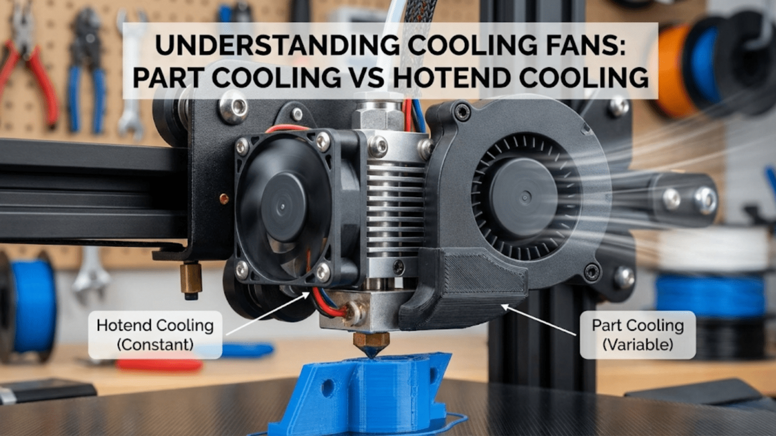
3D printers use two distinct cooling systems serving different purposes: the hotend cooling fan runs continuously at full speed to cool the heat sink and prevent heat creep from softening filament prematurely in the cold zone, while the part cooling fan blows variable-speed air onto freshly extruded plastic to rapidly solidify it, improving overhangs, bridges, and fine details. Both fans are essential but serve opposite functions—one keeps specific areas hot while the other cools the printed part.
Introduction
Air movement plays a paradoxical role in 3D printing. You’re working with molten plastic that needs to stay hot enough to flow and bond properly, yet that same plastic must cool and solidify quickly in the right places to maintain its shape. Managing this thermal dance requires two completely different cooling systems, each with its own fan, airflow pattern, control scheme, and purpose.
Many beginners don’t understand why their printer has multiple fans or what each one does. They might disable all cooling trying to solve warping, inadvertently causing heat creep jams. Or they might blast maximum cooling on everything, wondering why their ABS prints warp catastrophically. Understanding which fan does what—and why—transforms cooling from a mysterious setting you randomly adjust into a powerful tool you control strategically.
The hotend cooling fan and part cooling fan work in opposition yet both are essential. The hotend fan fights to keep heat where you want it—in the melt zone—while preventing it from migrating upward. The part cooling fan fights to remove heat from where you don’t want it—the freshly deposited plastic—allowing it to solidify into the correct shape. Both fans running simultaneously, one keeping things hot while the other makes things cold, might seem contradictory, but this delicate balance enables quality prints across diverse materials.
In this comprehensive guide, we’ll dissect both cooling systems, understanding their functions, configurations, and how to optimize them. You’ll learn why one fan never turns off while the other varies constantly, how cooling affects different materials differently, and when too much or too little cooling causes specific problems.
The Hotend Cooling System: Preventing Heat Creep
The hotend cooling fan serves a critical but often misunderstood purpose—maintaining the thermal gradient that keeps the melt zone precisely defined:
The Heat Creep Problem
Inside your hotend, a deliberate thermal gradient exists. The heater block maintains molten temperatures (190-300°C depending on material), while the area above—the heat break and heat sink—must stay much cooler. Solid filament enters from above, traveling through this cooler zone before reaching the melt zone.
If heat migrates upward from the melt zone (heat creep), it softens filament before it reaches the intended melting area. This softened filament expands slightly, creating friction against the heat break walls. As heating continues, the filament becomes increasingly soft and sticky, eventually jamming completely in the thermal transition zone.
Heat creep happens through conduction up the heat break and radiation warming the surrounding components. Without active cooling removing this migrating heat, the cold zone gradually warms until it’s no longer cold enough.
How Hotend Cooling Works
The hotend cooling fan addresses heat creep through forced convection:
Heat Sink Design: The heat sink—aluminum fins mounted above the heat break—provides large surface area for heat dissipation. The fins extend outward, creating pathways for airflow while maximizing exposure to moving air.
Continuous Airflow: A small axial fan (typically 30mm or 40mm) mounts to blow air across these fins continuously. Unlike the part cooling fan which varies speed, the hotend fan runs at 100% speed whenever the printer operates.
Thermal Gradient Maintenance: The constant airflow removes heat from the heat sink faster than conduction brings it upward from the melt zone. This maintains the sharp temperature gradient—hot below the heat break, cool above it—that prevents heat creep.
Heat Sink Effectiveness: The combination of large surface area fins and forced airflow creates efficient heat rejection. Even with the heater block just 20-30mm away maintaining 200+°C, the heat sink stays cool enough to touch (40-50°C) thanks to this active cooling.
Fan Specifications and Mounting
Hotend cooling fans have specific characteristics:
Size: Most use 30mm x 30mm x 10mm or 40mm x 40mm x 10mm axial fans. The compact size fits the space constraints around the hotend while providing adequate airflow.
Voltage: Typically 12V or 24V DC to match the printer’s power system. The fan receives constant voltage for continuous full-speed operation.
Airflow (CFM): Modest airflow requirements—usually 3-7 CFM (cubic feet per minute) suffices. Higher airflow helps but isn’t critical since the heat load is relatively small.
Static Pressure: More important than raw CFM for hotend fans. The fins create flow restriction, so the fan needs adequate static pressure to push air through the heat sink effectively.
Noise: Since this fan runs constantly at full speed, noise matters significantly. Quality fans (Sunon, Noctua) cost more but run much quieter than cheap alternatives.
Mounting: The fan mounts directly to the heat sink or to a bracket positioning it to blow across the fins. Proper alignment ensures airflow passes through the fin channels rather than around them.
Hotend Cooling Failure Modes
When hotend cooling fails, specific symptoms appear:
Heat Creep Jams: The most common consequence. Prints fail partway through as filament jams in the heat break. The jam typically occurs after printing for 20-30 minutes as heat gradually accumulates.
Inconsistent Extrusion: Before complete jamming, partial softening in the cold zone causes variable resistance. Extrusion becomes inconsistent—sometimes smooth, sometimes requiring extra motor force.
Temperature Fluctuations: Inadequate heat sink cooling can cause hotend temperature oscillations as heat from the block affects the thermistor reading despite the heater’s PID control.
Thermal Damage: Extended operation without cooling can degrade the heat break’s PTFE liner (if present), damage thermistor or heater cartridge insulation, or weaken the heat sink’s mounting.
Optimizing Hotend Cooling
Ensuring effective hotend cooling:
Verify Fan Operation: Check that the hotend fan spins freely and runs at proper speed. Listen for unusual bearing noise indicating impending failure.
Clean Heat Sink: Dust accumulation between fins reduces airflow effectiveness. Blow out dust monthly with compressed air.
Upgrade Fan Quality: Cheap fans fail prematurely. Replace stock fans with quality alternatives (Sunon, Noctua) for reliability and quieter operation.
Check Airflow Direction: Ensure the fan blows air through the heat sink fins, not just across the exterior. Some designs use ducting to channel airflow optimally.
Monitor Heat Sink Temperature: The heat sink should stay warm but not hot during printing. If it’s too hot to hold comfortably (>60°C), cooling may be inadequate.
The Part Cooling System: Solidifying Extruded Plastic
While hotend cooling maintains the thermal gradient inside the hotend, part cooling solidifies plastic after extrusion:
Why Part Cooling Matters
When molten plastic exits the nozzle, it must solidify quickly enough to maintain the intended shape:
Overhangs: Plastic deposited at angles greater than about 45° from vertical has limited support from previous layers. Without rapid cooling, gravity pulls this unsupported plastic downward before it solidifies, creating drooping, sagging overhangs.
Bridges: When printing must span empty space between two support points, the extruded plastic forms a bridge. Rapid cooling allows the plastic to stiffen quickly, preventing sagging in the middle of the span.
Fine Details: Small features like thin walls, sharp corners, and intricate details benefit from quick solidification. Plastic that stays molten too long can deform, round off corners, or blur fine details.
Layer Adhesion: Paradoxically, while we want layers to bond firmly, we also need each layer to solidify before the next layer deposits on top. The cooling rate affects this balance.
Dimensional Accuracy: Parts that cool too slowly can sag, warp, or deform, affecting dimensional accuracy. Controlled cooling maintains shapes better.
Part Cooling Fan Configuration
Part cooling systems differ significantly from hotend cooling:
Variable Speed Control: Unlike the always-on hotend fan, the part cooling fan speed varies during printing. The slicer controls fan speed based on layer time, feature size, and material-specific settings.
Typical Speeds:
- 0% for first layers (improving bed adhesion)
- Ramping up over layers 2-5
- 50-100% for most PLA printing
- 0-30% for ABS (high cooling causes warping)
- Material and feature-dependent for other plastics
Larger Fan Sizes: Part cooling often uses larger fans (40mm, 50mm, or even radial blowers) because they need to move more air across a larger area (the printed part) than hotend cooling’s focused heat sink.
Duct Systems: Unlike hotend fans that blow directly on fins, part cooling requires ducting to direct airflow precisely onto the nozzle area where plastic is being deposited.
Duct Design Principles
The duct channels airflow from the fan to the print zone effectively:
Directional Focusing: Ducts concentrate diffuse fan airflow into a stream directed at the area immediately surrounding the nozzle tip. This focuses cooling where freshly extruded plastic exists.
Multi-Directional Coverage: Quality ducts provide airflow from multiple directions (ideally 360° around the nozzle). This ensures consistent cooling regardless of print head direction or feature orientation.
Clearance: Ducts must direct air close to the nozzle without interfering with the printed part or limiting build volume. Compact designs balance airflow effectiveness with collision avoidance.
Heater Block Shielding: Good ducts minimize airflow hitting the heater block. Cooling the block wastes energy and can cause temperature instability.
Common Designs:
- Single-side ducts (basic, uneven cooling)
- Dual-side ducts (better than single, still directional bias)
- Ring ducts (excellent 360° coverage, more complex)
- Radial blower ducts (powerful airflow, efficient designs)
Radial Blowers vs. Axial Fans
Two fan types serve part cooling:
Axial Fans:
- Air enters and exits in the same direction (along the fan’s axis)
- Common sizes: 40mm, 50mm square fans
- Moderate airflow, lower static pressure
- Simpler, cheaper, quieter
- Work well with efficient duct designs
Radial Blowers (Centrifugal Fans):
- Air enters axially, exits radially (perpendicular to rotation)
- Common size: 40mm x 40mm x 20mm or 50mm x 50mm x 15mm “blower” style
- Higher static pressure, more focused airflow
- More efficient for ducted applications
- Louder operation, more expensive
- Better performance for demanding cooling needs
Most modern printer designs use radial blowers for part cooling because their higher pressure overcomes duct resistance more effectively, delivering stronger airflow where needed.
Material-Specific Cooling Requirements
Different materials demand different cooling approaches:
PLA:
- Benefits greatly from aggressive cooling
- 50-100% fan speed for most features
- Improves overhangs, bridges, details dramatically
- Minimal warping risk even with maximum cooling
- First layer: 0% (bed adhesion)
- Small features: 100% (prevent melting together)
PETG:
- Moderate cooling works best
- 20-50% fan speed typical
- Too much cooling reduces layer adhesion
- Too little causes stringing and poor overhangs
- Balance between bond strength and shape retention
ABS:
- Minimal cooling required
- 0-20% fan speed, often 0%
- High cooling causes severe warping and layer delamination
- Natural cooling from ambient air usually sufficient
- Enclosures help maintain warm environment
TPU/Flexible Filaments:
- Minimal to moderate cooling
- 0-40% depending on print speed and feature size
- Too much cooling can cause layer adhesion issues
- Benefits details and overhangs but risks weak prints
Nylon:
- Very minimal cooling, often none
- 0-10% maximum
- Extremely prone to warping with cooling
- Requires controlled temperature environment
High-Temperature Materials (Polycarbonate, etc.):
- Minimal or no part cooling
- 0-15% maximum
- Warping and layer adhesion concerns dominate
- Heated chambers preferred over forced cooling
Cooling Balance and Interaction
Understanding how both cooling systems interact reveals optimization strategies:
The Thermal Management Balance
Both cooling systems work simultaneously but serve opposite purposes:
Hotend Cooling: Maintains 100% output constantly, fighting heat migration upward, keeping the cold zone cold.
Part Cooling: Varies from 0-100%, rapidly cooling deposited plastic, removing heat from the printed part.
These systems operate in close proximity—separated by just 20-40mm—yet target different areas. Good printer design ensures part cooling airflow doesn’t blow directly on the hotend heat sink (wasting part cooling capacity) or heater block (destabilizing temperature control).
Layer Time and Cooling
The slicer considers layer time when setting part cooling fan speed:
Short Layer Times: Small features and top layers print quickly, meaning each layer has little time to cool before the next layer deposits. The slicer increases fan speed for these short layers to ensure adequate solidification.
Long Layer Times: Large layers take many seconds or minutes to complete, allowing natural cooling. The slicer may reduce fan speed since excessive cooling isn’t needed and might harm layer adhesion.
Minimum Layer Time: Some slicers include minimum layer time settings. If a layer would print too quickly, the slicer either slows down printing speed, increases cooling, or both to ensure proper solidification.
First Layer Cooling Strategy
First layers require special cooling consideration:
Bed Adhesion Priority: The first layer must stick firmly to the bed. Excessive cooling shrinks the plastic, creating stresses that lift corners and edges (warping).
Cooling Disabled: Most materials print the first layer with 0% part cooling to maximize bed adhesion and minimize warping risk.
Gradual Ramp-Up: Layers 2-5 gradually increase cooling from 0% to normal levels. This prevents sudden thermal shock while maintaining good bed adhesion.
Material Exceptions: Some materials (like PLA on PEI) may tolerate or even benefit from modest first-layer cooling (10-20%) without adhesion problems.
Cooling System Problems and Solutions
Various issues stem from cooling system malfunctions or incorrect configuration:
Hotend Cooling Problems
Heat Creep Jams:
- Symptom: Prints fail partway through with jams
- Cause: Hotend fan not running or inadequate airflow
- Solution: Verify fan operation, clean heat sink, upgrade fan
Temperature Instability:
- Symptom: Hotend temperature oscillates during printing
- Cause: Part cooling fan blowing on heater block
- Solution: Redesign duct to shield heater block, reduce part cooling
Premature Fan Failure:
- Symptom: Fan stops working after limited use
- Cause: Cheap fan quality
- Solution: Replace with quality fan (Sunon, Noctua)
Part Cooling Problems
Poor Overhangs/Bridges:
- Symptom: Drooping, sagging on angles and bridges
- Cause: Insufficient part cooling
- Solution: Increase fan speed, improve duct design, verify fan works
Warping:
- Symptom: Corners lifting, parts curling
- Cause: Excessive cooling for the material
- Solution: Reduce fan speed, disable for first layers, use enclosure
Weak Layer Adhesion:
- Symptom: Layers separate easily, weak parts
- Cause: Too much cooling preventing proper bonding
- Solution: Reduce fan speed, increase temperature slightly
Stringing and Oozing:
- Symptom: Fine strings between features, blobs
- Cause: Insufficient cooling allowing plastic to stay molten too long
- Solution: Increase fan speed, improve retraction settings
Melted Small Features:
- Symptom: Fine details melting, loss of definition
- Cause: Insufficient cooling for small features
- Solution: Increase fan speed, enable minimum layer time
Duct Problems
Uneven Cooling:
- Symptom: Quality varies by print direction
- Cause: Asymmetric duct providing cooling from only one side
- Solution: Upgrade to dual-side or 360° ring duct
Insufficient Airflow:
- Symptom: Fan runs but cooling inadequate
- Cause: Poor duct design creating excessive restriction
- Solution: Redesign with larger internal passages, shorter paths
Heater Block Cooling:
- Symptom: Temperature drops during high fan speeds
- Cause: Duct allows airflow onto heater block
- Solution: Add shielding, redesign duct
Cooling System Comparison Table
| Feature | Hotend Cooling Fan | Part Cooling Fan |
|---|---|---|
| Purpose | Prevent heat creep in heat sink | Solidify extruded plastic quickly |
| Operation | Continuous at 100% | Variable speed (0-100%) |
| Control | Always on when printer operates | Controlled by slicer per layer/feature |
| Typical Size | 30mm or 40mm axial | 40-50mm axial or radial blower |
| Airflow Target | Heat sink fins | Freshly deposited plastic near nozzle |
| Failure Impact | Heat creep jams | Poor quality, warping, or weak parts |
| Material Variation | Same for all materials | Highly material-dependent |
| Upgrade Priority | Medium (if failing or noisy) | High (major quality impact) |
| Critical Function | Yes (prevents jamming) | Yes (enables quality features) |
Optimizing Cooling for Quality
Strategic cooling optimization improves print quality:
Tuning Part Cooling Speed
Finding optimal cooling for your setup:
Start with Material Defaults: Slicer profiles provide reasonable starting points for each material.
Print Calibration Parts:
- Overhang test (stepped overhangs at 30°, 45°, 60°, 70°)
- Bridge test (spanning various distances)
- Detail test (fine features, thin walls)
Adjust and Compare:
- Print tests at different fan speeds (0%, 25%, 50%, 75%, 100%)
- Evaluate overhang quality, bridge sagging, detail definition
- Note layer adhesion (bend tests on thin samples)
Material-Specific Tuning: Create profiles for each material with appropriate cooling based on testing.
Duct Upgrades
Improving part cooling effectiveness:
Evaluate Current Performance: Identify cooling weaknesses:
- Do overhangs sag on one side but not others? (Asymmetric cooling)
- Generally poor bridges despite high fan speed? (Insufficient airflow)
- Temperature instability? (Heater block cooling)
Select Upgrade Path:
- Single-side to dual-side (moderate improvement)
- Dual-side to ring duct (substantial improvement)
- Axial fan to radial blower (airflow boost)
- Custom designed for specific hotend (optimal fit)
Installation and Testing: After installing new ducts, retest cooling performance and verify temperature stability.
Environmental Cooling Control
Managing ambient conditions:
Enclosures for ABS/Nylon: Trapping heat reduces warping. The enclosure maintains elevated ambient temperature, reducing thermal gradients that cause warping.
Controlled Drafts: Eliminate air currents from HVAC vents, windows, or doors. Uncontrolled drafts cool unevenly, causing warping and quality issues.
Chamber Heating: Advanced setups actively heat print chambers for high-temperature materials, completely controlling the thermal environment.
Advanced Cooling Concepts
Dynamic Cooling Algorithms
Modern slicers implement sophisticated cooling control:
Layer Time-Based: Automatically adjusts fan speed based on layer print time. Short layers get more cooling; long layers need less.
Feature-Based: Different fan speeds for:
- External perimeters (full cooling for quality)
- Internal perimeters (moderate cooling for strength)
- Infill (minimal cooling, speed priority)
- Bridges and overhangs (maximum cooling)
Gradual Transitions: Smoothly ramping fan speed prevents sudden thermal shocks that cause artifacts.
Directed Cooling Strategies
Some advanced systems allow asymmetric cooling:
Directional Ducts: Independently controlled ducts cool different sides separately. This enables:
- Stronger cooling on overhang sides
- Reduced cooling on sides needing layer adhesion
- Directional control based on print geometry
Multiple Fans: Some printers use multiple independently controlled part cooling fans for precise thermal management.
Active Temperature Monitoring
Advanced printers monitor part temperature:
IR Sensors: Measure actual part surface temperature during printing, allowing closed-loop cooling control.
Thermal Cameras: Visualize temperature distribution, identifying hot spots and optimizing cooling patterns.
Adaptive Control: Adjust cooling in real-time based on measured temperatures rather than preset speeds.
Maintenance and Reliability
Keeping cooling systems working optimally:
Regular Maintenance Schedule
Monthly:
- Clean dust from heat sink fins
- Verify both fans spin freely
- Check duct alignment and security
- Listen for bearing noise indicating wear
Quarterly:
- Deep clean heat sink with compressed air
- Inspect fan blades for damage
- Test part cooling effectiveness with test prints
- Verify secure wire connections
Annually:
- Consider preventive fan replacement (especially hotend fan)
- Evaluate duct design for potential upgrades
- Deep clean entire cooling system
Fan Replacement Guidelines
When to Replace:
- Bearing noise develops (grinding, clicking)
- Fan doesn’t reach full speed
- Visible blade damage
- After 2000-3000 operating hours preventively
Quality Matters: Invest in quality fans:
- Sunon, Noctua for quiet, reliable operation
- Proper voltage rating (12V or 24V matching system)
- Adequate CFM/static pressure specs
- Appropriate physical dimensions
Conclusion
The cooling systems in your 3D printer—both the continuous hotend fan and variable part cooling fan—work together to manage the complex thermal requirements of additive manufacturing. Understanding that one keeps specific areas appropriately hot while the other strategically cools deposited plastic reveals why both are essential and how they must be optimized differently.
The hotend cooling fan might seem simple—it just runs at 100% all the time—but its continuous operation prevents heat creep jams that would otherwise ruin prints hours into their creation. This fan deserves quality investment and regular maintenance because its failure stops printing completely.
The part cooling fan requires more sophisticated understanding because its optimal settings vary dramatically by material, feature size, and quality priorities. Too much cooling causes warping and weak layer adhesion; too little results in sagging overhangs and poor details. Finding the right balance for each material transforms print quality.
Together, these cooling systems enable the thermal control necessary for successful 3D printing. The hotend fan maintains the precise temperature gradient inside the hotend while the part cooling fan solidifies plastic into the correct shapes. Both running simultaneously, managing heat in opposite ways, creates the delicate thermal balance that makes quality prints possible.
Whether you’re troubleshooting cooling problems, upgrading ducts for better performance, or simply trying to understand why your printer has so many fans, knowledge of these systems empowers better printing. The next time you hear those fans spinning—one constantly, one varying—appreciate the sophisticated thermal management happening right before your eyes, enabling the transformation of molten plastic into the precise objects you design.