Introduction: Why Position Matters More Than You Think
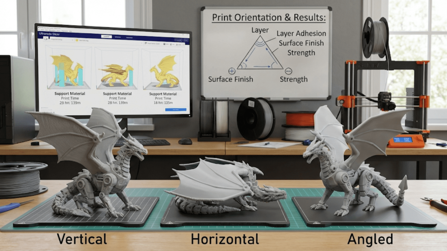
When beginners first start 3D printing, there’s often an assumption that once you’ve loaded a model into your slicing software, the hard part is over. You just click print and wait for your object to materialize, right? In reality, one of the most consequential decisions you’ll make for any print happens before you ever send it to the printer. That decision is how you orient your model on the virtual build plate. The way you position and rotate your model in three-dimensional space before slicing has profound effects on print quality, structural strength, print time, material usage, and even whether the print succeeds at all.
Think about building a brick wall. You could stack bricks the normal way, with each brick lying flat and the layers running horizontally, creating a strong, stable structure. Or you could try standing the bricks on end, creating vertical columns of bricks balanced on their edges. Both arrangements use the same bricks, but one is obviously much stronger and more stable than the other. The same principle applies to 3D printing, where the orientation of your model determines how the layers stack up to form the final object.
The fundamental reason orientation matters so much comes from the layer-by-layer nature of FDM printing. Unlike a solid piece of metal or injection-molded plastic that has uniform properties in all directions, a 3D printed object is inherently anisotropic, meaning its properties differ depending on direction. The bonds between layers are typically weaker than the bonds within layers, creating a grain-like structure similar to wood. Just as wood splits more easily along the grain than across it, 3D prints are weaker in certain directions based on how the layers are oriented.
Beyond strength considerations, orientation affects how surfaces appear. The top surface of a print, built up layer by layer, looks dramatically different from a side surface that’s perpendicular to the build plate. Curved surfaces show more or less pronounced layer stepping depending on their angle. Features that require support material to print successfully can be minimized or eliminated entirely by clever orientation choices. The time required to complete a print can vary by a factor of two or three just by changing orientation, even when printing the exact same model.
Understanding print orientation transforms you from someone who just accepts whatever default position the model loads in to someone who can strategically position models to achieve specific goals. Whether you’re prioritizing strength for a functional part, minimizing visible layer lines on a display piece, reducing print time for a prototype, or maximizing the likelihood of print success, orientation is one of your most powerful tools. This article explores all the factors that should influence your orientation decisions and provides practical strategies for positioning models to achieve your specific objectives.
Understanding Layer Lines and Surface Quality
The most immediately visible effect of print orientation is how it influences the appearance of different surfaces on your finished print. Layer lines, those characteristic horizontal ridges that mark where each layer of plastic was deposited, are the signature of FDM printing. Their prominence and visibility depend entirely on which way the model was oriented during printing, and understanding this relationship is fundamental to controlling the appearance of your prints.
When a surface is perfectly horizontal and parallel to the build plate, it’s built up one complete layer at a time. The top surface, in particular, consists of the final few layers of the print where the slicer generates solid infill to cap off the internal structure. This creates a relatively smooth surface with a pattern determined by the direction and strategy the nozzle follows while depositing those top layers. Most slicers create a rectilinear pattern for top surfaces, with lines running back and forth in alternating directions on each layer. This creates a characteristic surface texture, but it’s generally much smoother than the stepped appearance of layer lines on angled surfaces.
The bottom surface of a print, the one that sits on the build plate, has its own unique characteristics. The first layer is typically printed slightly thicker and more slowly than subsequent layers to ensure good adhesion to the build surface. This first layer gets squished down against the bed, creating a smooth but slightly different texture than upper surfaces. If you’re using a textured build plate, that texture will be imprinted onto the bottom surface. If you’re using a smooth glass bed, the bottom will be glossy and quite smooth. This means that keeping important visible surfaces as either top or bottom faces during printing can produce superior surface quality compared to having them on the sides.
Side surfaces that are perpendicular to the build plate tell a completely different story. These surfaces are formed by the edges of each successive layer stacking up like a staircase. Each layer creates a small step, and these steps are the layer lines you see on vertical surfaces. The height of each step is determined by your layer height setting. A print with zero point one millimeter layer heights will have finer, less noticeable layer lines than a print with zero point three millimeter layer heights. But regardless of layer height, those lines will be visible on vertical surfaces in a way they’re not on horizontal surfaces.
Angled surfaces present the most interesting challenge for surface quality. When a surface is at an angle between horizontal and vertical, each layer still creates a step, but the visibility and prominence of that step depends on the angle. A surface at a very shallow angle, nearly horizontal, will show relatively smooth results because each layer only extends slightly beyond the previous one. The steps are small and gradual. A surface at a steep angle, close to vertical, will show more pronounced stepping because each layer must extend farther to follow the angled contour. The worst case scenario is typically surfaces angled around thirty to sixty degrees from horizontal, where layer lines are most visible and create the most pronounced stair-stepping effect.
Curved surfaces deserve special consideration. A sphere or cylinder, when printed vertically, will have smooth sides formed by vertical layers but may show slight polygonal faceting in circular cross-sections due to the discrete nature of the toolpath. The same sphere printed horizontally will show pronounced layer lines across its curved surface, creating a ridged appearance. However, the circular profile itself will be perfectly smooth since it’s formed within a single layer. This means that for cylindrical objects like wheels, pins, or shafts, orienting them horizontally often produces the smoothest, most circular cross-section, even though the length will show layer lines.
The strategic lesson here is to orient your model so that the most important visible surfaces are either perfectly horizontal or at angles that minimize the visibility of layer stepping. If you’re printing a decorative object that will be displayed from a particular viewing angle, position it so that the surfaces facing the viewer are as close to horizontal as possible. If you’re printing something functional where one surface needs to be particularly smooth for mechanical reasons, like a sliding surface or sealing surface, try to make that surface either a top or bottom surface during printing.
For objects where all surfaces are equally important and visible, you may need to make compromises. Sometimes this means accepting some layer lines as inevitable. Other times it means using post-processing techniques like sanding or filling to improve surfaces that couldn’t be optimized through orientation alone. And sometimes it means splitting a complex model into multiple parts that can each be oriented optimally for their respective surfaces, then assembling them after printing. Understanding how orientation affects surface appearance gives you the knowledge to make these informed decisions.
The Critical Importance of Layer Orientation for Strength
If surface appearance were the only consideration, print orientation would be important but relatively straightforward. However, mechanical strength considerations often dominate orientation decisions for functional parts, and the strength differences between different orientations can be dramatic. Understanding why layer orientation affects strength so profoundly is essential for anyone printing parts that will bear loads or experience stress during use.
The fundamental issue is that bonds between layers are significantly weaker than the material within each layer. When the printer deposits a layer of hot plastic onto the previous layer, the two layers fuse together as the new plastic partially melts the surface of the old layer. This fusion creates a bond, but it’s not as strong as the continuous material within each layer. The degree of bonding depends on many factors including material type, printing temperature, cooling rate, and the cleanliness of the previous layer’s surface, but in virtually all cases, the interlayer bond is the weakest link.
To understand the practical implications, imagine a simple printed hook designed to hang from a rod and support weight below it. If you print this hook standing upright with the curve going vertically, the layers will run horizontally through the hook. When you hang weight from this hook, the forces will try to pull the layers apart, putting stress directly on those weaker interlayer bonds. The hook is likely to fail by delaminating, with layers separating from each other. This is the weakest possible orientation for this application.
Now imagine printing the same hook lying on its side, so the curve of the hook runs horizontally and the layers go through it vertically. In this orientation, the forces from the suspended weight are trying to bend the hook, creating tension on one side and compression on the other, but these stresses are within the layers rather than between them. The hook takes advantage of the continuous material within each layer and is dramatically stronger. It might still eventually break, but it will likely bend significantly before failing and will support far more weight than the first orientation.
This principle extends to all functional parts. Whenever possible, you want loads to be carried within layers rather than between layers. Tension forces pulling on a part should run along the layer direction, not perpendicular to layers. Bending forces should be oriented so that the tension and compression zones are within layers. Impact forces should hit surfaces that are perpendicular to layers rather than parallel to them, as layers are more resistant to compression than to being pulled apart.
The anisotropic nature of 3D printed parts means you need to think about the stress the part will experience during use and orient it accordingly during printing. For a bracket that will be bolted to a wall and support weight below it, you want the layers to run vertically through the bracket so the weight hangs from continuous layers rather than trying to pull layers apart. For a lever that will be pushed or pulled during use, you want layers oriented so the force runs along the layers. For a gear that will transmit torque, you want layers running through the gear teeth so the forces from meshing with other gears don’t try to shear layers apart.
Complex parts with loads in multiple directions present challenges. You can’t always orient a part optimally for every possible stress it might encounter. In these cases, you need to identify the critical load, the force that’s most likely to cause failure or that’s most important for the part’s function, and orient for that load primarily. Secondary concerns can be addressed through design changes like increasing wall thickness, adding ribs or gussets, or choosing stronger infill patterns. The key is that orientation should be driven by understanding what stresses the part will face in actual use.
Some parts benefit from being split into multiple components, each printed in its optimal orientation, then assembled. A T-shaped bracket, for example, might be strongest if the vertical post and horizontal arm are printed as separate pieces, each with layers running along their length, then joined with mechanical fasteners or adhesive. While this adds assembly work, it can create parts that are far stronger than a single-piece print could achieve. The decision to split parts should balance the strength improvement against the added complexity and the strength characteristics of whatever joining method you use.
Material selection interacts with orientation in important ways. Some materials have better interlayer bonding than others. PETG, for example, typically produces better layer adhesion than PLA, meaning the strength difference between orientations may be less dramatic. Materials like nylon or polycarbonate, when printed at high temperatures, can achieve excellent layer bonding. Materials like ABS that are prone to warping and layer separation may show more pronounced anisotropy. Understanding your material’s characteristics helps you assess how critical orientation will be for strength in any particular application.
Minimizing and Managing Support Structures
Support structures represent wasted material, added print time, and post-processing work. They also leave marks on surfaces where they contact the model, degrading surface quality. One of the most powerful benefits of thoughtful orientation is the ability to minimize or eliminate the need for supports entirely. Understanding how overhangs work and how orientation affects support requirements is essential for efficient printing.
The basic physics of overhang is straightforward. When the printer deposits a layer of molten plastic, that plastic needs something beneath it to support its weight while it cools and solidifies. If the previous layer extends directly under the new material, that’s perfect support. If the previous layer is offset slightly inward, the new layer can still bridge out over it to some degree, with cooling helping solidify the plastic before it has time to droop significantly. But if the offset becomes too large, the plastic will sag or droop before solidifying, ruining the print.
The maximum angle at which plastic can successfully overhang without support is typically between forty-five and sixty degrees from vertical, depending on material, cooling, and print settings. Surfaces shallower than this angle need support, while surfaces steeper than this angle can print without it. A perfectly vertical wall needs no support. A perfectly horizontal ceiling needs complete support underneath. Surfaces at intermediate angles fall somewhere between these extremes, and whether they need support depends on the specific angle and your printer’s capabilities.
Orientation can transform a print that requires extensive support into one that needs minimal or no support. Consider a simple shelf bracket with a horizontal arm extending from a vertical back plate. If printed with the back plate down on the bed and the arm extending horizontally, the underside of the arm is a large horizontal surface requiring support across its entire area. But if you rotate the bracket ninety degrees so both the back plate and arm are at forty-five degrees from the build plate, no surfaces exceed the maximum overhang angle and no supports are needed. The print takes slightly longer due to the increased height, but eliminating supports often more than makes up for this.
Strategic orientation decisions can isolate support requirements to less critical surfaces. If supports are unavoidable, try to orient the model so supports contact surfaces that won’t be visible in the final application or where surface quality doesn’t matter. The bottom surface sitting on the build plate will have perfect quality with no support marks, so that’s the ideal place for your visible surface. Any supports needed for overhangs on other parts of the model can be positioned where they’re less problematic.
Some models can be split into sections printed separately, each in an orientation minimizing supports, then assembled. A complex organic shape like a figurine might have significant overhangs no matter how you orient it. But if you separate the arms from the body, each piece can be oriented optimally to minimize its individual support needs. After printing, the pieces are glued or mechanically fastened together. While this requires more work than a single print, the improved surface quality and reduced material waste often justify the effort.
Understanding bridging, the printer’s ability to span gaps between supported points, helps you minimize supports for certain geometries. Small holes and gaps can often be bridged successfully without support, even when they technically violate the overhang angle rule. The key is that bridging works across relatively short distances where the plastic can span from one supported point to another before sagging. Orienting your model to turn what would be large unsupported areas into series of shorter bridges can eliminate support needs. For example, a part with multiple holes might need supports if oriented one way, but if rotated so the plastic can bridge across each hole individually, the supports become unnecessary.
Some slicing software offers options for support placement and density that should inform your orientation decisions. Tree supports, which grow up from the build plate and branch out to contact only the areas that truly need support, can be much easier to remove than traditional grid-style supports. If your slicer offers tree supports, you might accept some support requirements knowing they’ll be relatively easy to remove. Support interface layers, thin sacrificial layers between supports and the model, improve surface quality where supports contact the model. Understanding these options helps you make orientation decisions with full knowledge of the consequences.
There are cases where adding supports is the better choice despite the drawbacks. If achieving necessary strength requires a particular orientation that happens to need supports, accept the supports and plan for the surface finishing work. If rotating to eliminate supports would triple the print height and quadruple the time, supports might be the more efficient choice. Orientation decisions involve weighing multiple factors, and minimizing supports is just one consideration among many. The goal is making informed decisions that optimize for your specific priorities, which will vary from print to print.
Print Time Optimization Through Orientation
Print time may not seem like something that orientation would affect significantly, but the way you position your model can easily change print duration by a factor of two or more. Understanding the mechanisms by which orientation influences print time helps you make strategic choices when speed is a priority, such as for prototypes or when you need parts urgently.
The most direct effect comes from the number of layers required to build the model. A model printed with its shortest dimension vertical will complete faster than the same model printed with its longest dimension vertical, simply because fewer layers are needed. Consider a rectangular box that’s one hundred millimeters long, fifty millimeters wide, and twenty millimeters tall. Printed standing upright on the fifty by one hundred millimeter face, it’s twenty millimeters tall and might need one hundred to two hundred layers depending on your layer height. Rotate it to stand on the twenty by fifty millimeter end, and it becomes one hundred millimeters tall, requiring five hundred to one thousand layers. The print could take five times longer just from this change.
However, layer count isn’t the only factor. Travel moves, where the print head moves without extruding material, also consume time. A tall, thin print requires the print head to move up a tiny amount after completing each layer, potentially traveling back to the starting point, then printing the next layer. For very small layers, the actual printing might be quick, but the accumulation of travel moves adds up. A short, wide print might have more complex geometry within each layer, requiring more intrusion moves and more travel between features, but there are fewer layers overall. The balance between these factors determines actual print time.
Layer time minimums also come into play. Many slicing programs include minimum layer time settings to ensure each layer has adequate time to cool before the next layer is added. For tiny layers that would complete very quickly, the printer slows down or pauses to ensure this minimum time is met. This prevents the problem of adding new layers before previous layers have solidified, which would cause the print to become a melted mess. Tall, thin prints with small layer cross-sections may spend significant time waiting for cooling, even though the actual printing is fast. Reorienting to create larger layers that naturally take longer to print can actually reduce total time by eliminating this forced delay.
Infill generation can interact with orientation in ways that affect print time. Some infill patterns are optimized for layers of certain shapes or sizes. A long, narrow layer might generate infill more efficiently than a small, complex layer. The slicer’s algorithm for determining infill patterns may make different choices based on layer geometry, and these choices can influence print time. Additionally, the interaction between infill and perimeters changes based on the shape of each layer, potentially creating more or fewer separate regions that need individual processing.
Support structures add time proportional to their volume and complexity. An orientation that eliminates supports entirely can save substantial time compared to an orientation requiring extensive support, even if the support-free orientation results in more layers. Supports take time to print and time to remove, so factoring in the complete workflow rather than just the printing time proper provides a more accurate comparison. A print that finishes faster but requires thirty minutes of careful support removal might not actually be the quickest path to a completed part compared to a longer print that needs no post-processing.
For parts being printed in quantity, orientation decisions can dramatically affect production throughput. Being able to fit more parts onto the build plate by orienting them compactly means fewer total print jobs to complete a batch. A part that’s one hundred millimeters tall when printed vertically but only twenty millimeters tall when printed horizontally might allow five times as many copies to fit on the build plate when horizontal, turning five separate print jobs into one. The per-part time is longer, but the total time to produce the batch is much less.
Strategic time optimization recognizes that not every print has the same priorities. Prototypes and test fits often prioritize speed, accepting compromises in surface quality or strength to get results quickly. Reorienting for minimum height and eliminating supports makes sense for these applications. Final production parts may prioritize quality or strength, accepting longer print times. Understanding your priorities for each specific print guides appropriate orientation choices.
The Build Plate Adhesion Factor
Getting your print to stick properly to the build plate for the duration of the print is fundamental to success. Orientation affects the contact area between the model and build plate, the shape of that contact area, and the forces trying to pull the print loose. Understanding these relationships helps you orient models to maximize adhesion and minimize the risk of print failure from detachment.
The first layer’s contact with the build plate creates the foundation for the entire print. A larger contact area generally means better adhesion, all else being equal. More surface area means more bonds between the plastic and the build surface, creating stronger attachment. A model with a large, flat bottom surface oriented against the build plate will adhere well. A model balanced on a small point or thin edge will have poor adhesion and likely fail during printing.
However, contact area alone doesn’t tell the complete story. The shape of the contact area matters for resisting the forces that try to dislodge the print. Warping forces, where plastic contracts as it cools and tries to curl upward from the edges, create powerful stresses. A wide, flat base with long edges exposes more perimeter that can warp. A more compact, circular base might have less overall area but also less perimeter prone to warping and might actually be more reliable. For materials like ABS that are highly prone to warping, orientation choices that minimize the perimeter-to-area ratio of the first layer can significantly improve success rates.
Center of gravity and stability during printing influence adhesion requirements. A tall print with a small base is top-heavy and can be knocked over by the force of the print head moving rapidly past it, even if the initial adhesion was adequate. Orienting prints to be shorter and wider creates more stable geometry. If a tall, narrow orientation is necessary for other reasons like strength or surface quality, you might need to add a brim or raft to increase the base size and improve stability.
Brims and rafts are supportive structures that the slicer can add to improve adhesion, and the need for them depends partly on orientation. A brim is a thin, flat skirt of material printed around the base of the model, increasing the contact area without affecting the model itself. A raft is a thick platform printed beneath the entire model, providing a large, stable base. Prints oriented with small base areas often benefit from brims or rafts, while prints with large, flat bases may not need them. Choosing an orientation with adequate base area can eliminate the need for these features, saving time and material.
Different areas of the build plate sometimes have different adhesion characteristics. The center of the bed may be more level or at slightly different temperature than the edges. If your printer has adhesion challenges in certain regions, orienting your model to place its footprint in the most reliable area of the bed can improve success. Understanding your specific printer’s characteristics through experience guides these placement decisions.
The material being printed affects how orientation and adhesion interact. PLA generally adheres well and is not particularly prone to warping, so orientation choices for PLA can prioritize other factors with reasonable confidence in adhesion. PETG can stick too well, sometimes bonding so strongly to build surfaces that it damages them upon removal, so orientations that minimize contact area might actually be preferable. ABS requires careful attention to warping, making orientation choices that minimize warp-prone geometry critical. Each material has its own adhesion personality that should influence orientation decisions.
Some models can be oriented to take advantage of the build plate for functional purposes. If you need one surface of your part to be perfectly flat, orienting that surface against the build plate ensures flatness, as the bed itself serves as a reference surface. The first layer pressed against the bed will be as flat as the bed itself. This can be useful for parts that need to sit flush against other surfaces or that need a datum surface for mounting.
Dealing with Tall, Unstable Orientations
Sometimes the optimal orientation for strength or surface quality produces a tall, narrow print that seems precarious. These prints present special challenges because they can fail in ways that shorter, more stable orientations don’t. Understanding the specific risks and mitigation strategies for tall prints allows you to use these orientations when their benefits outweigh the risks.
The primary risk with tall, narrow prints is mechanical instability during the printing process. As the print head moves back and forth, especially during rapid travel moves, it can strike the growing print with sufficient force to knock it loose from the build plate or even tip it over. This is particularly problematic once the print gets taller, as the lever arm effect means a force near the top of the print creates significant moment at the base. A print that adhered perfectly initially can still fail hours into the printing process if it grows too tall and unstable.
Adhesion becomes more critical for tall prints. The base attachment must be strong enough to resist not just the print’s weight but the lateral forces from the print head’s movement. Ensuring perfect bed leveling, using adhesion aids like glue stick or hairspray if appropriate for your surface and material, and potentially adding a brim become more important. The first layer must be absolutely perfect because any weakness will be amplified as the print grows taller.
Print speed reduction helps mitigate risks for tall prints. Slower movements of the print head reduce the forces imparted when it changes direction or travels past the print. Many users create special printer profiles for tall, narrow prints that reduce all speeds by twenty to thirty percent. The print takes longer, but the success rate improves dramatically. The time investment is worthwhile because a failed print wastes all the time already invested plus the material used.
Strategic use of support structures can stabilize tall prints even when supports aren’t strictly needed for overhangs. Adding support material that connects the model to the build plate in multiple places or that creates a wider base can significantly improve stability. These aren’t supports in the traditional sense of holding up overhanging material, but rather structural reinforcement to prevent the print from tipping. The supports are removed after printing just like traditional supports, but their presence during printing makes success much more likely.
Retraction settings interact with tall print stability in important ways. If your retraction settings cause the nozzle to lift during travel moves, called Z-hop, the nozzle is less likely to collide with the print during travel. However, aggressive Z-hop with tall prints can sometimes cause problems if the print is unstable enough that the nozzle actually catches on it during the hop-up movement. Tuning retraction and Z-hop settings for tall prints requires finding a balance that avoids both collision during travel and catching during hop.
Environmental factors affect tall prints disproportionately. Air currents from windows, air conditioning, or fans can cause uneven cooling that leads to warping, particularly problematic with materials like ABS. A tall print presents more surface area to these currents and is more likely to warp. Enclosures that protect the print from drafts become more important for tall prints than for squat, stable ones. Temperature variation throughout the print’s height can also cause issues, with the top of a very tall print being noticeably cooler than the bottom.
Multi-part printing strategies can avoid the challenges of very tall single-piece prints. If a design can be split horizontally into two or three shorter sections that are printed separately then assembled, each section can be printed in a more stable orientation. The final assembled part is as tall as needed, but the printing process never requires building an unstable tower. This approach trades assembly work for improved print reliability and may be the pragmatic choice for designs that would otherwise require exceptionally tall prints.
Circular and Cylindrical Parts: Special Considerations
Parts with circular cross-sections or cylindrical features present unique orientation challenges because the way you orient them dramatically affects different aspects of the final part. Understanding these specific considerations helps you make informed choices when printing wheels, pins, shafts, pulleys, and other round features.
Orienting a cylinder horizontally, with its axis parallel to the build plate, produces the most accurate circular cross-section. Each layer represents a slice through the cylinder, and the slicer generates a circular perimeter for each layer. The resulting cross-section is as perfectly circular as your printer’s XY resolution allows, limited only by the discrete nature of the toolpath. If you need a pin or shaft that fits into a hole with tight tolerances, horizontal orientation typically produces the most accurate diameter. The trade-off is that the length of the cylinder will show layer lines, and those lines run perpendicular to the axis, potentially affecting surface finish in ways that matter for some applications.
Vertical orientation of cylinders, with the axis perpendicular to the build plate, produces smooth sides without visible layer lines running along the length. For applications where the side surface is important, like a wheel that rolls or a decorative cylinder, vertical orientation creates superior surface finish along the sides. However, the circular cross-section becomes approximated by the polygonal toolpath within a single layer, which may show slight flattening or faceting. The degree of faceting depends on the cylinder’s diameter and the printer’s resolution, with larger diameters generally producing better circles than small ones.
Internal holes and cylinders face similar considerations but with additional complications. A vertically-oriented cylinder means printing layers that have circular holes in them, which the printer must bridge across in small segments. The bottom of the hole, unless it’s a straight hole through the entire part, will require support material. A horizontally-oriented internal cylinder means each layer has a different shaped hole as you progress through the part, with the bottom of the hole being an overhang that may sag or require support. For through-holes, horizontal orientation often produces the most accurate diameter, though the hole’s interior surface will show layer lines.
Threaded features like bolts or nuts represent a special case of cylindrical parts with critical functional requirements. The threads must be accurately sized and shaped to engage properly with mating parts. Orienting threaded parts with the axis horizontal generally produces the most accurate thread profile because the threads are formed within each layer’s perimeter. Vertical orientation means the threads are formed by layer steps, which can create weak points where layers might separate under load. For functional threaded parts that will bear significant force, horizontal orientation despite its longer print time and potential need for supports often provides more reliable results.
Wheels and gears that need to spin smoothly on axles or mesh with other gears require careful orientation decisions. A wheel printed vertically will have a smooth outer circumference but may have an imperfect central hole. A wheel printed horizontally will have an accurate central hole but may show layer lines on the rim. For wheels that roll freely, vertical orientation might be preferable. For gears where the teeth must mesh precisely, horizontal orientation often provides better results because the teeth are formed by the XY resolution rather than by layer stepping.
Concentricity, the alignment of multiple circular features sharing a common axis, can be affected by orientation. If a part has a larger outer cylinder and a smaller inner hole that must be perfectly concentric, orienting the axis horizontally ensures both circles are formed within the same layers, maintaining concentricity as accurately as the printer can manage. Vertical orientation might accumulate slight errors between layers that cause the inner and outer circles to drift out of alignment over the part’s height.
Split-orientation strategies can sometimes provide the best of both approaches for cylindrical parts. If a pulley needs both a smooth outer rim and an accurate inner hole, you might print the rim and hub separately in their optimal orientations then join them mechanically or with adhesive. The added complexity may be worthwhile for parts with demanding requirements that can’t be fully satisfied by any single orientation.
When Orientation Conflicts: Prioritizing Your Requirements
In an ideal world, you could orient every model perfectly for strength, surface quality, print time, and adhesion simultaneously. In reality, these factors often pull in different directions, and choosing an orientation means prioritizing which factors matter most for the specific part you’re printing. Developing a systematic approach to these trade-offs helps you make consistent, rational decisions.
Start by clearly identifying the part’s function and critical requirements. Is this a structural part that must bear loads without failing? Then strength is paramount, and orientation should primarily serve that goal even if it means accepting longer print times or rougher surfaces. Is this a display piece where appearance is everything? Surface quality becomes the priority, and you’ll accept some compromises in strength or print time. Is this a quick prototype for testing a design concept? Print time optimization moves to the top of the priority list, and you’ll accept compromises everywhere else to get results quickly.
For functional parts, load analysis drives orientation decisions. Identify the primary forces the part will experience and orient to make the layers perpendicular to those forces when possible. If multiple significant loads exist, identify which is most likely to cause failure or is most critical to the application. Orient for that critical load and address secondary concerns through design modifications like increased wall thickness or reinforcement features. Document your reasoning so you can revisit the decision if the part doesn’t perform as expected.
For aesthetic parts, identify which surfaces will be most visible and prioritize their quality. The back side of a wall-mounted decoration doesn’t matter as much as the front face. The bottom of a display piece sitting on a shelf is less important than the top and sides. Orient to make the most critical surfaces either perfectly horizontal or at angles that minimize visible layer lines. If certain features need to be particularly sharp or detailed, orient so those features are formed by the XY resolution rather than by layer stacking.
When requirements truly conflict and no orientation satisfies all needs, consider whether the part can be split into multiple components. A bracket that needs strength in one direction and smooth surfaces in another might be impossible to optimize as a single piece but could be split into parts that are each printed in their optimal orientation then assembled. The joints between parts become considerations in themselves, but for demanding applications, this approach can be the only way to meet all requirements.
Create a mental or written checklist of orientation considerations for each print. Does this need to be strong? In what direction? Does surface quality matter? On which surfaces? Are there overhangs that need support? Can orientation eliminate them? Is print time a concern? How tall will the print be in different orientations? Working through these questions systematically ensures you consider all relevant factors before committing to a choice.
Experience builds intuition about these trade-offs. Early in your 3D printing journey, you might print test pieces in multiple orientations to understand the differences. As you gain experience, you’ll develop pattern recognition that helps you quickly assess orientations without needing to test every possibility. You’ll recognize that certain types of parts almost always benefit from specific orientations based on their geometry and requirements. This accumulated knowledge accelerates decision-making while still allowing you to think carefully about unusual cases.
Don’t be afraid to iterate. If your first orientation choice doesn’t produce satisfactory results, analyze what went wrong and choose a different orientation for the second attempt. Part of the 3D printing learning process is developing judgment about orientations, and that judgment comes partly from seeing what works and what doesn’t. Failed prints provide valuable lessons if you take time to understand why they failed and what different choices might have prevented the failure.
Advanced Orientation Techniques: Rotation and Angles
Beyond the basic choice of which face sits on the build plate, subtle rotations and precise angles can sometimes provide benefits for specific situations. These advanced orientation techniques require more careful thought but can solve problems that basic orientations can’t address.
Angling a part at forty-five degrees to the build plate can sometimes eliminate support requirements that would be needed at zero or ninety degrees. This works because forty-five degrees is often right at the threshold of what the printer can bridge successfully. A surface that would need support if horizontal might print successfully at forty-five degrees. A surface that would be too shallow if angled only thirty degrees might work at forty-five. While this orientation isn’t optimal for either strength or surface quality compared to purely horizontal or vertical, the elimination of supports and their associated quality problems might make it the best overall choice.
Rotating parts around the vertical Z-axis affects how the slicer generates toolpaths and where it places seam lines. The seam is the point where the nozzle completes each layer’s perimeter and starts the next layer, often visible as a vertical line on the print. Different rotational orientations place this seam on different parts of the model. You can strategically rotate to place the seam on the least visible surface or even on a sharp corner where it’s naturally camouflaged. While this doesn’t change the fundamental orientation of up versus down, it affects aesthetic quality.
Multiple parts arranged on the build plate benefit from strategic rotation to maximize plate utilization. Parts that would conflict if all placed at the same angle might fit together efficiently if rotated relative to each other. This optimization puzzle resembles packing boxes, where rotation and positioning work together to fit the maximum number of parts in the available space. Efficient plate usage means fewer print jobs to complete a batch and more productivity.
Spiral or helical parts sometimes benefit from orienting the central axis at an angle rather than purely vertical or horizontal. This creates layers that follow the helical path more naturally, potentially producing better results than either pure orientation. Springs, augers, helical gears, and similar parts might print more accurately or with better strength when angled appropriately. The optimal angle depends on the helix angle of the part itself and requires some experimentation.
Parts with multiple cylindrical features at different angles present orientation puzzles where no single orientation optimizes all features. In these cases, you might choose an orientation that compromises between the ideal angles for different features, accepting that none will be perfect but all will be adequate. Alternatively, recognizing that the part can’t be optimally printed as a single piece might drive a decision to split it into subassemblies, each oriented for its specific geometry.
Creating custom supports through geometry modifications represents an advanced technique where you add material to the model itself that serves a support function, then is removed after printing like traditional supports but with better control over placement and removal. These geometric supports can be oriented optimally because they’re part of the model, not generated by the slicer. This is particularly useful for complex organic shapes where traditional support algorithms struggle to provide adequate support without excessive material use.
Test prints at multiple orientations provide empirical data when the optimal orientation isn’t clear from analysis alone. For critical parts where success is paramount, printing the same model at two or three different orientations and comparing the results provides definitive information about which orientation works best for your specific combination of printer, material, and requirements. The material investment in multiple test prints is often justified when it prevents a larger batch of parts from being printed in a suboptimal orientation.
Learning from Failures: Orientation Post-Mortem Analysis
Failed prints provide valuable lessons about orientation choices, but only if you take time to analyze what went wrong and why. Developing the habit of post-mortem analysis after failures accelerates your learning and helps you avoid repeating mistakes. Understanding the specific failure modes associated with orientation problems makes future orientation decisions more informed.
Layer delamination or splitting, where the print separates along layer lines during or after printing, almost always indicates that forces were oriented perpendicular to layers. If you see this failure mode, revisit your orientation choice with a focus on layer direction relative to the loads the part experienced. The solution is typically to reorient so layers are parallel to the primary stress rather than perpendicular to it. This might mean sacrificing surface quality or increasing print time, but if delamination caused failure, those compromises are necessary.
Warping or detachment from the build plate suggests the contact area was inadequate for the adhesion forces or that the part’s geometry was particularly prone to warping in that orientation. Analyze whether a different orientation would provide more contact area or a more compact footprint. Consider whether adding a brim or changing bed preparation might help, or whether the orientation itself should change. Sometimes rotating a part by ninety degrees dramatically changes its warping behavior by altering which edges are prone to curling.
Support-related surface defects indicate that supports were needed and contacting critical surfaces. The question is whether better support settings could have improved the situation or whether a different orientation might have eliminated or relocated the supports. If the surface quality problems are on the most visible or functional surfaces, reorienting to move those surfaces away from support contact points should be a priority for the next attempt.
Dimensional accuracy problems where certain features consistently print wrong might relate to orientation. Features formed by layering might print oversized, while features formed within a single layer might be more accurate. Holes that are too small when printed vertically might be correctly sized when printed horizontally. Understanding which dimensions are off and by how much guides orientation adjustments. Sometimes the solution involves both orientation changes and dimensional compensation in the model design.
Visible layer lines on critical surfaces suggest that those surfaces should be oriented differently to minimize stepping. If a display piece shows unacceptable layer texture on its most visible face, reorienting to make that face more horizontal or at a shallower angle should improve results. Document which orientations produced unacceptable surface quality so you can avoid them for similar parts in the future.
Prints that knocked loose during printing due to instability need obvious corrections, but the lesson extends beyond just that specific print. Tall, narrow orientations are inherently risky and should be avoided unless their benefits clearly outweigh the reliability concerns. Building intuition about when tall orientations are worth the risk versus when choosing a more stable orientation is pragmatic comes from seeing what fails and what succeeds.
Keeping records of orientation choices and outcomes, even informally, helps build your knowledge base. Photos of failed prints with notes about the orientation and failure mode create a personal reference library. Over time, patterns emerge that inform future decisions. You’ll notice that certain types of parts always fail in specific orientations but succeed in others. This pattern recognition becomes an invaluable part of your orientation decision-making process.
Conclusion: Making Orientation Decisions with Confidence
Print orientation represents one of the most impactful decisions you make for every 3D print, yet it’s often given less attention than it deserves, particularly by beginners. Understanding how orientation affects strength, surface quality, print time, adhesion, and success rate transforms this from a casual decision into a strategic choice that significantly influences outcomes. The investment in learning to evaluate orientations systematically and make informed choices pays dividends in the form of stronger parts, better looking surfaces, more efficient prints, and fewer failures.
The key insight is that no single orientation is universally best. Each print has its own requirements, and the optimal orientation balances multiple competing factors based on what matters most for that specific application. Developing a systematic approach to orientation decisions ensures you consider all relevant factors rather than defaulting to whatever orientation the model loads in or arbitrarily choosing based on a single consideration like print time. This systematic thinking becomes faster with experience but starts with consciously working through the considerations for each print.
The anisotropic nature of FDM printing, where layer bonds are weaker than material within layers, is fundamental to understanding orientation’s effect on strength. Internalizing this concept helps you quickly assess whether an orientation will produce parts strong enough for their intended use. The ability to look at a part, understand the forces it will experience, and orient it so layers are perpendicular to those forces becomes intuitive with practice but starts with conscious application of the principle.
Surface quality considerations require understanding how layer lines appear on different surfaces and recognizing that horizontal surfaces print differently than vertical or angled surfaces. The ability to identify which surfaces matter most for appearance and orient the part to optimize those surfaces while accepting compromises on less critical surfaces demonstrates mature orientation decision-making. Sometimes this means accepting longer print times or dealing with supports, but the result is parts that look right where it matters.
The relationship between orientation and supports is often the most immediately obvious benefit of careful positioning. The ability to eliminate or minimize supports through clever orientation saves time, material, and post-processing work while improving surface quality. Developing the spatial reasoning to mentally rotate parts and visualize how overhangs change with different orientations is a valuable skill that grows stronger with deliberate practice.
As you gain experience, you’ll build a mental library of orientation patterns for common part types. Brackets typically orient one way for strength, decorative plaques another way for surface quality, and cylindrical parts in yet another way for accuracy. This accumulated knowledge accelerates decision-making while remaining flexible enough to handle unusual cases that don’t fit established patterns. The goal isn’t rigid rules but informed judgment that considers each part’s specific needs.
The willingness to iterate and learn from failures is perhaps the most important aspect of mastering orientation decisions. No amount of theoretical knowledge eliminates the need to sometimes try different approaches and see what works. The printer is your ultimate teacher, and failed prints provide lessons that successful prints can’t. Taking time to understand why failures occurred and how different orientations might have prevented them builds expertise more effectively than any amount of reading or theorizing alone.
Looking forward, as your 3D printing journey progresses, orientation decisions become more nuanced and sophisticated. You’ll begin considering factors like how to orient parts for specific post-processing techniques, how orientation affects color in multi-color prints, or how to position parts to minimize filament changes in multi-material prints. The foundational understanding of how orientation affects strength, surface quality, and printability remains central, but additional layers of consideration build on that foundation.
The ultimate goal is making orientation decisions with confidence born from understanding rather than hoping for the best. When you position a model on the virtual build plate, you should be able to articulate why that orientation serves your goals, what trade-offs you’re accepting, and what you expect the results to be. This confidence comes from understanding the principles discussed in this article and from the experience of seeing those principles play out in practice. Every print is an opportunity to refine your orientation decision-making, building toward mastery of this fundamental 3D printing skill.