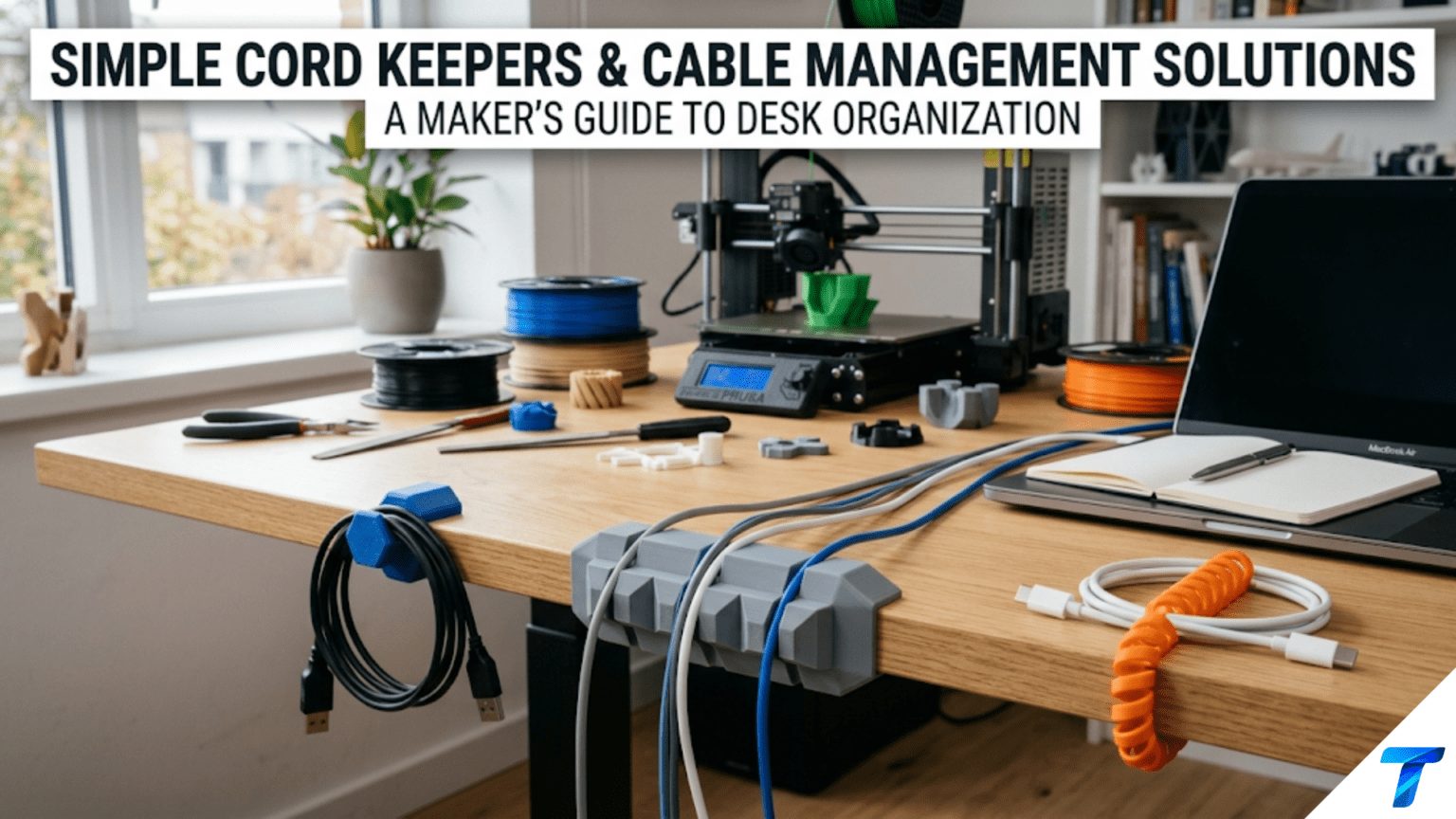
3D printed cord keepers and cable management solutions are custom-designed clips, wraps, organizers, and channels that keep charging cables, headphone cords, power cables, and other wiring neatly organized, tangle-free, and accessible. They are among the most immediately useful beginner printing projects because cable clutter is a universal household problem, the individual pieces print in 5–20 minutes, and the accumulated effect of a complete cable management system — desk, entertainment center, bedside table — is a dramatically tidier space achieved for a few grams of filament.
Introduction: The Invisible Problem That’s Everywhere
Cable clutter is one of those problems that people stop noticing precisely because it’s everywhere. The tangle of charging cables on the bedside table. The mess of power bricks under the desk. The headphone cord that inevitably wraps itself around the chair leg. The television power strip with six cables radiating in different directions. The kitchen counter where three device chargers compete for the same outlet and their cables cross in a Gordian knot.
These tangles are not merely aesthetic problems, though they are certainly that. Tangled and improperly managed cables wear faster at stress points, create tripping hazards, make it difficult to identify which cable belongs to which device, and generate a low-level visual chaos that research consistently links to reduced focus and increased stress in work environments.
The commercial cable management market exists precisely because these problems are universal — but commercial solutions are generic. A cable clip designed for an “average” cable diameter fits many cables and none of them perfectly. A cable organizer box accommodates “most” power bricks and creates dead space around the ones it doesn’t fit. A cord keeper wraps “standard” headphone cables but is too small for thicker cables and too large for earphone cords.
Your printer solves cable management with specificity. A clip designed for the exact diameter of your specific charging cable. A keeper sized to the exact cord length that needs to be coiled. A cable channel custom-fitted to the exact gap between your desk and the wall. These solutions eliminate the compromise that generic products require — they work perfectly because they were designed for the specific cables, spaces, and use patterns of your specific setup.
This guide covers the complete range of cable management printing: the types of solutions worth making, the dimensions that matter for each cable type, materials for different environments, slicer settings for small functional pieces, mounting approaches, and a systematic method for auditing and solving the cable management problems in every room of your home.
Understanding Your Cable Management Problem
Before printing anything, spend five minutes auditing the cable situations you want to solve. Cable management printing is most effective when targeted at specific, understood problems rather than printed speculatively.
The Cable Management Audit
Walk through your home and photograph or note every cable management problem:
Problem types to identify:
- Tangle zones: Where cables for multiple devices cross and tangle (bedside tables, desk surfaces, entertainment centers)
- Loose trailing cables: Cables that run across floor or desk surfaces without being routed or secured
- Drop points: Where cables fall off desks or table edges when devices are disconnected, requiring retrieval from behind furniture
- Length excess: Cables that are longer than needed and bunch up or coil messily
- Identification problems: Cables that are identical and indistinguishable from each other
For each problem, note:
- The cable diameter (measure with calipers or look up the cable type)
- The cable length and the distance it needs to travel
- The surface it needs to attach to (wood, plastic, drywall, tile)
- How frequently the cable needs to be disconnected and reconnected
This audit takes 10–15 minutes but guides the entire cable management project, ensuring you print solutions that actually match the problems you have.
Standard Cable Diameters
Different cable types have standard diameter ranges:
| Cable Type | Typical Diameter | Notes |
|---|---|---|
| USB-C charging cable (standard) | 3.5–4.5mm | Varies by brand |
| USB-A cable | 4–5mm | Standard USB-A |
| Lightning cable | 3.5–4mm | Apple devices |
| Headphone cable (full size) | 3.5–5mm | Varies by quality |
| Earphone cable (in-ear) | 1.5–2.5mm | Very thin |
| Power brick cable | 5–8mm | Thicker insulation |
| Ethernet cable | 6–7mm | Standard Cat5e/Cat6 |
| HDMI cable | 8–12mm | Significant variation |
| Extension cord | 10–14mm | Much thicker |
| USB-C fast charging cable | 5–7mm | Thicker for current capacity |
Measure your specific cables with digital calipers for the most accurate clip sizing — published standards have real-world variation, and a clip designed for 4mm that encounters a 5mm cable won’t work.
Types of Cord Keepers and Cable Management Solutions
Type 1: Cable Drop Clips (Desk Edge Clips)
The most immediately useful cable management piece: a clip that attaches to the edge of a desk and holds a cable at the desk edge, preventing it from dropping off the desk when a device is disconnected.
Without a cable drop clip, every time you pick up your phone or laptop from your desk, the charging cable falls behind the desk. With a cable drop clip, the cable hangs neatly at the desk edge, ready to reconnect without retrieval.
Design specifications:
- Desk edge grip: The clip must grip the desk edge securely. Measure your desk thickness (typically 18–25mm for most desks). The clip opening should be desk thickness + 0.5mm for a firm grip.
- Cable channel: A circular channel on the clip face that holds the cable. Inner diameter = cable diameter + 0.5–1mm clearance.
- Cable retention: The channel opening should be slightly narrower than the cable diameter (by 0.3–0.5mm) so the cable snaps in with a slight resistance but stays in place.
Design in Tinkercad:
- Create a C-shaped clamp body (the desk edge grip section): Two horizontal arms with the opening sized for desk thickness
- Add a cable channel ring on the front face of the clamp: a partial torus or cylinder with the cable-snap opening at the front
Print orientation: Print with the desk-edge opening facing upward. This puts the layer lines parallel to the grip arms, in the direction of compression when the clip is on the desk.
Material: PETG recommended. The desk-edge grip experiences repeated flex (opening and closing as the clip is put on and removed). PLA can develop fatigue cracks at the clip opening after repeated flex cycles.
Type 2: Cable Wrap / Cord Keeper
A spool or figure-eight wrap that stores excess cable length neatly. Rather than allowing a long cable to coil randomly, the cord keeper provides an organized wrap.
Types of cord keepers:
Figure-eight keeper: Two loops in a figure-eight pattern. The cable wraps in a figure-eight around the two posts, eliminating the memory-coil tangling that round coils develop over time. Minimal material, elegant solution.
Spool-style keeper: A simple flat spool with a center hub and two side flanges. The cable winds around the hub between the flanges. Works well for longer cables that need more wrapping length. The flanges prevent the cable from unwinding accidentally.
Yoyo-style keeper: A cylindrical keeper with a slot that the cable loads into tangentially. The cable wraps inside the cylinder and the connector end emerges through the slot. More complex to design but produces a very tidy result.
Design specifications for figure-eight keeper:
- Post diameter: 12–15mm (large enough not to create a kink in the cable)
- Post height: 8–12mm (tall enough to hold multiple wraps without spilling over)
- Post spacing: 25–35mm center-to-center
- Base thickness: 3–4mm
- Overall dimensions: approximately 65–80mm × 25mm × 10–15mm
Cable length capacity: Each complete figure-eight wrap consumes approximately (post spacing × 2 + post circumference × 2)mm of cable. For posts 30mm apart: (60mm + ~40mm) × number of wraps. A 1.5m cable can typically wrap 8–12 times around a standard figure-eight keeper.
Type 3: Wall Cable Clips
Flat clips with a cable channel that attach to a wall surface, routing cables neatly along wall edges, behind furniture, or from outlet to device.
Design specifications:
- Body: A flat rectangular base (25–40mm × 20–30mm × 5–8mm) with a circular cable channel on the front face
- Cable channel: Same snap-in design as desk edge clips
- Mounting: Either a single screw hole through the center, or an adhesive-backed mounting flange
Cable clip varieties worth printing:
- Single cable clip: Holds one cable. Most common type.
- Dual cable clip: Two channels side by side for routing two cables together along the same path.
- Corner cable clip: Angled at 90° for routing cables around corners without kinking.
- Under-desk clip: A clamp or adhesive clip for mounting under a desk surface, keeping cables routed along the underside and out of sight.
Wall adhesive options:
- Command adhesive strips for drywall (follow weight limits — cable clips are very light)
- 3M VHB foam tape for harder surfaces
- A single small screw for permanent installation
Type 4: Cable Box / Power Strip Organizer
An enclosure for a power strip and power bricks that hides the mess of multiple cables and bricks in a single, organized container.
Design specifications:
- Interior: Sized to fit your specific power strip (measure carefully — leave 5–10mm clearance on all sides for ventilation)
- Cable exit slots: Openings sized for the number and types of cables exiting the box
- Ventilation: The box must not trap heat from power bricks — include ventilation slots or holes on top and sides (minimum 20–30% open area)
- Access: A removable lid or door for accessing the strip if needed
- Material: PETG or ASA for better heat resistance near power bricks. Do not use PLA near heat sources.
Safety note: Power strips and power bricks generate heat. Any enclosure must allow adequate ventilation. Never fully enclose power electronics in a sealed container. If an enclosure causes any components to feel warmer than normal, add ventilation immediately.
Type 5: Cable Identification Tags
Small tags that attach to cables (either around the cable or sliding over the plug) identifying what each cable belongs to. In a tangle of identical black USB cables, identification tags eliminate the “which one is which?” problem entirely.
Design approaches:
- Ring tags: A ring that slides over the cable (design the ring ID slightly larger than the cable diameter + 1mm). Ring is embossed or debossed with an identifier: “PHONE,” “TABLET,” “DESK LAMP,” etc.
- Wrap tags: A flat tag with a loop that wraps around the cable and clips to itself (snap-fit closure).
- Plug end tags: A flag-style tag that attaches to the USB plug end, dangling beside the plug.
Batch printing: Print cable tags in batches for all cables in a given area. A set of 10 labeled tags for all the cables in a home office takes about 45 minutes to print and completely eliminates cable identification confusion.
Type 6: Velcro / Cable Tie Holders
Cable tie alternatives: printed holders that keep cables organized using printed snap-fit straps rather than disposable zip ties.
Design: A flat strap with snap-fit closure — one end has a tab, the other has a socket. The strap wraps around a coiled cable or bundle and clicks shut. Unlike zip ties, these can be opened and reused indefinitely.
Specifications:
- Strap width: 10–12mm
- Strap thickness: 1.5–2mm (flexible enough to wrap around cable bundles)
- Snap closure: 0.5–0.8mm overhang on the snap tab
- Material: TPU for maximum flexibility and durability, or PETG for adequate flex without TPU’s printing challenges
Design Principles for Cable Management Pieces
The Cable Snap-In Principle
For any clip that holds a cable by snapping it in rather than permanently enclosing it, the snap opening geometry is critical. The opening should be:
- Narrower than the cable by 0.3–0.5mm (so the cable requires slight force to snap in but stays once in)
- Rounded edges at the opening to prevent abrasion of the cable insulation
- Flexible enough in the clip arm material to allow the cable to snap in without fracturing the clip
Material matters here: PLA will eventually crack at the snap opening edges after enough insertions and removals. PETG’s better flexibility makes it the right choice for any cable clip that will be used frequently.
The Mounting Adhesion Problem
Many cable clips mount to surfaces using adhesive. The common failure mode: the adhesive bond fails and the clip falls off, usually taking the cable with it and potentially damaging the cable or the surface.
Design for better adhesion:
- Maximize the mounting face area (larger footprint = larger adhesive area)
- Keep the mounting face as flat as possible — any warp in the print reduces effective adhesive contact area
- Print at 0.15mm layer height for the mounting face to ensure maximum flatness
- Use proper mounting adhesive for the surface type (Command strips are designed for drywall; 3M VHB foam tape is better for smooth plastic and metal surfaces)
Alternative to adhesive: Design clips with a magnetic mounting option — a recess in the back of the clip for a small neodymium magnet, pairing with a magnetic strip on the desk or wall. Magnetic mounting is repositionable and stronger than adhesive for light loads like cable clips.
Cable Stress Points
Cables fail at stress points — places where the cable is bent repeatedly or where force concentrates. Good cable management avoids creating stress points:
- Don’t design clips that force cables into tight bends. The cable routing radius at any clip should be at least 5× the cable diameter. For a 4mm cable: minimum 20mm bend radius.
- Route cables to avoid repeated flexing. A cable that flexes every time a device is moved will fail faster than one routed to flex in a controlled, consistent way.
- Anchor cables near their plug ends. The highest-stress point on a cable is where it exits the connector housing. Clips that hold the cable close to the plug end protect this critical stress point.
Slicer Settings for Cable Management Pieces
Cable management clips are small, functional parts. The priorities are dimensional accuracy (clips must fit specific cable and surface dimensions) and durability (snapping in and out repeatedly).
| Setting | Recommended Value | Notes |
|---|---|---|
| Layer Height | 0.15–0.2mm | 0.15mm for better snap geometry accuracy |
| Print Speed | 40–50 mm/s | Moderate |
| Outer Wall Speed | 20–25 mm/s | Accurate outer walls for precise cable fit |
| Perimeters/Walls | 3–4 | Adequate for small functional clips |
| Infill | 25–35% | Grid; clips don’t need high structural infill |
| Top/Bottom Layers | 4 | Standard |
| Support | None | Design clips to print without support |
| Bed Adhesion | Brim (3mm) | Small brim for small parts |
| Minimum Layer Time | 8 seconds | Small parts benefit from cooling time |
| Cooling | 90–100% | Maximum for dimensional accuracy |
| Seam Position | Rear or least visible | Seam away from functional surfaces |
Batch Printing Cable Clips
Cable management is solved systems, not individual clips. You need multiple clips per cable run, multiple cable runs per room, multiple rooms per house. Batch printing is the efficient approach.
For a standard build plate (220mm × 220mm), you can typically fit:
- 12–16 small desk edge clips
- 8–12 wall cable clips
- 6–10 cord keepers
- 20–30 cable identification tags
Print clips in large batches — a full plate of 16 desk edge clips takes only slightly longer than printing 4 individually, and you have a complete supply for all the cables on your desk.
Spacing for batch printing: Space small cable clips 20–25mm apart. Set minimum layer time to 8 seconds to prevent heat accumulation in the small parts.
Step-by-Step: Building a Complete Desk Cable Management System
Let’s build a complete cable management system for a typical home office desk with 6 cables.
Step 1: Audit the Desk
Identify and measure all cables on the desk:
- Laptop power cable: 7mm diameter, runs from left side of desk to power strip under desk
- USB-C phone charger: 4mm diameter, needs to stay accessible at desk edge
- USB-C tablet charger: 4mm diameter, same requirement as phone
- Headphone cable: 4.5mm diameter, tends to tangle around chair
- Ethernet cable: 6.5mm diameter, runs from router to computer
- Monitor power cable: 8mm diameter, runs from monitor to power strip
Problems identified:
- Phone and tablet chargers fall behind desk when disconnected (need desk edge drop clips)
- Headphone cable tangles (needs cord keeper)
- Laptop, ethernet, and monitor cables run loosely across desk surface (need wall routing clips)
Step 2: Design or Source Clips
For each problem type, find or design appropriate clips:
- Phone and tablet charger drop clips: Desk edge clip for 4mm cable, desk thickness 22mm. Design clip opening: 22.5mm. Cable channel: 4.5mm inner diameter.
- Headphone cord keeper: Figure-eight keeper. Post diameter: 14mm; post spacing: 30mm.
- Cable routing clips: Wall clips for 7mm, 6.5mm, and 8mm cables. Design three variants. Single screw mounting.
Step 3: Slice All Parts Together
Import all clip files into one slicer session:
- 2 desk edge clips (one for phone, one for tablet)
- 1 headphone cord keeper
- 3 wall routing clips (different sizes)
Arrange on build plate. Apply settings:
- 0.15mm layer height
- 3 perimeters
- 30% Grid infill
- 8-second minimum layer time
- PETG at 237°C / 80°C bed
Estimated print time: 1.5–2 hours for all pieces.
Step 4: Print and Test Fit
Before mounting anything, test each clip with its target cable:
- Snap each desk edge clip onto the desk edge — should grip firmly, not too tight
- Snap each cable into the desk edge clip — should snap in with moderate force, stay in place
- Test the cord keeper with the headphone cable
- Test each wall clip with its cable
Adjust any clips that are too tight or too loose before mounting.
Step 5: Mount the System
Desk edge clips: Press onto the desk edge at the chosen positions. No adhesive needed for desk-edge clips — the grip mechanism holds them in place.
Wall cable clips: Use Command adhesive strips on the underside of the desk for routing clips, or single small screws for permanent wall-mounted clips. Route each cable to its clip, press cable into channel.
Cord keeper: Keep in a desk drawer or mount to the desk leg — use when storing headphones.
Step 6: Dress the Cables
Route each cable through its clips in sequence. Ensure no tight bends at any clip. Bundle excess cable length with a printed cable strap. The result: a desk where each cable has a defined path, charger cables are always accessible at the desk edge, and the headphone cable has a dedicated keeper.
Room-by-Room Cable Management
Bedroom / Bedside Table
Typically holds: phone charger, tablet charger, lamp cable, alarm clock cable, possibly earphone cable and headphone cable.
Key solutions:
- Desk-edge drop clips for phone and tablet cables (prevent the midnight fumble for a fallen cable)
- Nightstand side routing for lamp cable
- Small cord keeper for earphone cable
- Cable identification tags for all chargers
Entertainment Center / TV Area
Typically the most complex cable management situation: TV, streaming device, game console, soundbar, power strip, router — each with multiple cables.
Key solutions:
- Cable box for the power strip and associated power bricks
- Wall cable channels routing cables along the wall edge or behind the TV stand
- Cable identification tags for all HDMI and device cables
- Cable anchors at device locations to prevent cables from moving when devices are accessed
Kitchen
Typically holds: phone charger, device charger, small appliance cables.
Key solutions:
- Counter cable clips for cables that run along the counter backsplash
- Cabinet-mounted cord keepers for appliance cables when appliances are stored
- Drawer cable organizer for spare cables
Home Office
Addressed in the step-by-step above. The home office typically has the highest cable density and benefits most from systematic management.
Creative Cable Management Projects
Under-Desk Cable Spine
A complete cable spine system for the underside of a desk — a series of printed clips and channels that route all desk cables in a unified channel running along the underside of the desk from devices to the power strip. All cables disappear from view, managed in a single organized spine.
Design: A central channel clip (mounted with 3M VHB tape or screws under the desk) that accommodates 4–6 cables together, with branches where individual cables diverge to their devices. The system can be as simple (clips at regular intervals) or sophisticated (fully enclosed channel with removable top) as the use case requires.
Modular Cable Management System
A Gridfinity-inspired modular cable management system where each module handles one aspect — one cable type, one routing direction, one organization function — and modules connect to each other with a standardized interface. The system can be built up incrementally as needs change.
Magnetic Cable Anchor
A cable holder with an embedded magnet that sticks to the metal frame of a desk, workbench, or appliance. The cable snaps into the holder, and the holder moves freely on any magnetic surface. Repositionable without adhesive, without tools, without damage to surfaces.
Cable Identification Color System
Rather than labeling cables with text, use a color-coded system: print identification rings in different colors and slip them over cables at both ends — red for phone, blue for tablet, yellow for laptop, green for headphones. The color coding is faster to read than text and works even when cables are tangled.
Troubleshooting Common Cable Management Print Issues
Clip Is Too Tight — Cable Won’t Snap In
Cause: Cable channel inner diameter is too small; FDM dimensional variation made the channel smaller than designed.
Solution: Increase inner diameter by 0.5mm and reprint. For existing clips, carefully enlarge the channel with a round file or sandpaper wrapped around the appropriate diameter dowel.
Clip Is Too Loose — Cable Falls Out
Cause: Channel inner diameter is too large; cable is thinner than expected; snap opening is too wide.
Solution: Reduce inner diameter by 0.3mm. Reduce snap opening by the same amount. For existing loose clips, apply a thin strip of foam tape inside the channel to reduce effective diameter.
Desk Edge Clip Doesn’t Grip the Desk Firmly
Cause: Clip opening is wider than the desk thickness; PETG’s slight flexibility allowing the clip to spread.
Solution: Reduce clip opening to desk thickness − 0.5mm (so the clip is slightly undersized and grips by spring force). Increase clip arm thickness to reduce flex.
Wall-Mounted Clip Adhesive Fails
Cause: Wrong adhesive for surface type; surface wasn’t clean at mounting time; clip mounting face is warped reducing adhesive contact.
Solution: Use surface-appropriate adhesive. Ensure surface is cleaned with isopropyl alcohol and fully dry before mounting. Print clip at 0.15mm layer height for maximum flat mounting surface. Use the largest practical mounting face area.
Cable Identification Tags Slip Along Cable
Cause: Tag ring inner diameter is too large for the cable; tag slides freely along the cable rather than staying in position.
Solution: Reduce ring inner diameter to cable diameter − 0.3mm (slight interference fit grips the cable). Add a small bump or raised ridge on the inner surface of the ring to grip the cable insulation. Use a cable tie (zip tie) to position the tag if slip-resistance is essential.
Conclusion: The Organized Space Behind the Scenes
Cable management is infrastructure. Nobody notices it when it works. Everyone notices it when it doesn’t. The tangle of cables that nobody knows how to fix, the charging cable that always has to be retrieved from behind the furniture, the power strip that’s a fire hazard of crammed-in bricks — these are the background stresses of modern life.
Your printer addresses them with a specificity that feels disproportionate to the size of the pieces it makes. A clip that takes 8 minutes to print and 30 seconds to install eliminates a daily frustration that might otherwise continue for years. A cord keeper that costs a few cents of filament takes the headphone tangle problem from annoying to solved.
Print the clips for the specific cables in your specific spaces. Measure first. Design or find solutions that match what you actually have. Install systematically.
Then appreciate the quiet satisfaction of a desk where cables stay where they belong, devices are always connected and accessible, and the visual noise of cable clutter is simply gone.
Small prints. Big difference.