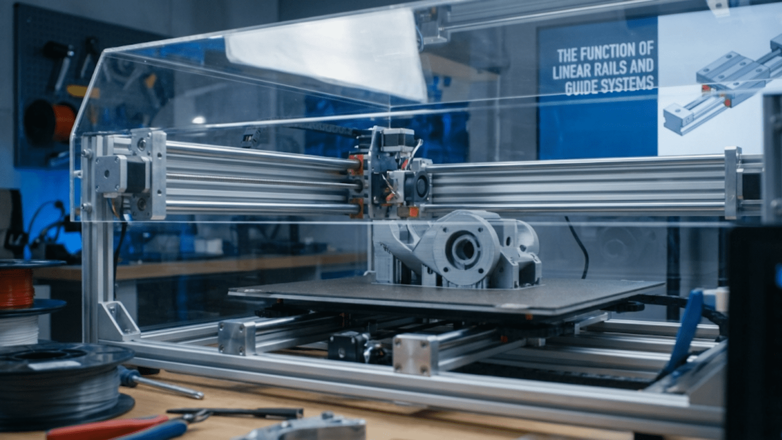
Linear rails and guide systems constrain moving components to precise straight-line motion while supporting their weight and resisting forces from multiple directions, forming the foundation of accurate 3D printer positioning. Common systems include linear rods with sliding bearings, linear rails with recirculating ball bearing carriages, and V-slot wheels running in grooved aluminum extrusion, each offering different balances of cost, precision, rigidity, and maintenance requirements while all serving the essential function of ensuring the print head, bed, or gantry moves exactly where commanded without deviation or wobble.
Introduction
Every movement your 3D printer makes depends on components traveling in perfectly straight lines. When the X-axis moves left, it must move purely horizontally without tilting, lifting, or deviating from its path. When the Z-axis raises the print head, it must rise vertically without any lateral drift. Any deviation from these ideal straight-line movements appears as defects in your prints—layer misalignment, dimensional inaccuracy, or surface artifacts.
Linear rails and guide systems provide this critical constraint. They’re the tracks that keep everything moving where it should, supporting weight while allowing smooth, precise motion along intended paths. Without them, your printer would be a pile of motors and controllers with no way to create controlled, accurate movement.
Yet these systems remain poorly understood by many users. Terms like “LM8UU bearings,” “MGN12 rails,” and “V-slot wheels” confuse beginners. The differences between linear rods and linear rails seem mysterious. Why do some printers use one system while others use something completely different? What makes one approach better than another?
Understanding linear motion systems transforms them from mysterious components into logical mechanical solutions you can evaluate, maintain, and optimize. You’ll recognize why your printer uses its particular system, understand the tradeoffs involved, and know how to keep everything moving smoothly for optimal print quality.
In this comprehensive guide, we’ll explore every major linear motion approach used in 3D printers, understanding how each works, what advantages and limitations they present, and how to maintain them properly for long-term precision.
The Linear Motion Challenge
Before examining specific solutions, understanding the fundamental challenge reveals why linear guides are so critical:
Constraint Requirements
Any moving component in a 3D printer needs constraint in multiple directions simultaneously:
Five Degrees of Freedom Constraint: A carriage moving along the X-axis needs to be constrained in five directions while allowing free movement in the sixth:
- Y-axis translation (prevented): Can’t move forward or backward
- Z-axis translation (prevented): Can’t move up or down
- Rotation around X (prevented): Can’t tilt side-to-side (roll)
- Rotation around Y (prevented): Can’t tilt front-to-back (pitch)
- Rotation around Z (prevented): Can’t rotate in the horizontal plane (yaw)
- X-axis translation (allowed): Free to move left and right as commanded
The linear guide system must constrain all the unwanted movements while offering minimal resistance to the desired motion direction.
Load Support
The system must support various loads:
Static Load: The weight of the moving component itself—the carriage, hotend, extruder, and any attached hardware. This creates continuous downward force on the guide system.
Dynamic Loads: Acceleration and deceleration create inertial forces. Rapid direction changes multiply the effective load many times beyond static weight.
Moment Loads: When the carriage extends far from the support point (cantilever), it creates rotational forces (moments) trying to tilt the carriage. The guide system must resist these twisting forces.
External Forces: Printing operations can introduce external forces—nozzle drag across the surface, resistance from pushing filament, impacts from failed prints or collisions.
Precision and Repeatability
The guide system determines positioning accuracy:
Straightness: The guide must be straight within tight tolerances. Any bow, curve, or kink in the guide appears as position error in that area.
Repeatability: Moving to the same position repeatedly must arrive at exactly the same location. Slop, play, or backlash in the guide system creates position variation.
Rigidity: The system must resist deflection under load. Flex creates position errors that vary with load and carriage position.
Linear Rod Systems
Linear rods with sliding bearings represent the traditional solution common in many 3D printers:
Construction and Components
Linear Rods: Hardened steel rods, typically 8mm or 10mm diameter, serve as the guide rails. These must be:
- Perfectly straight (within 0.1mm over their length)
- Smooth cylindrical surface finish
- Hardened for wear resistance
- Parallel to each other (in systems using paired rods)
Linear Bearings: Bearings slide along the rods, providing the moving interface. The most common type is the LM8UU (Linear Motion, 8mm bore, Ultra-Ultra short):
Recirculating Ball Bearings: Inside the bearing housing, steel balls circulate through races machined into the housing and contacting the rod surface. As the bearing slides along the rod, balls roll between the housing and rod, then recirculate through return paths back to the beginning of the race.
Bearing Length: Longer bearings provide more support and better moment resistance but add friction and weight. LM8UU is “ultra-ultra short” (24mm length for 8mm rod). Longer variants (LM8LUU) provide 45mm length for greater stability.
Bearing Quality: Quality varies enormously:
- Cheap bearings: Rough machining, loose tolerances, noisy operation, short lifespan
- Quality bearings: Precision grinding, tight tolerances, smooth quiet operation, durability
- Linear bushings: Lower-cost alternative using sliding plastic or bronze instead of ball bearings
Advantages of Rod Systems
Low Cost: Linear rods and basic bearings cost relatively little. An 8mm rod and LM8UU bearing system costs a fraction of equivalent linear rail systems.
Availability: Rods and bearings are commodity items available from numerous sources. Replacement parts are easy to find.
Simplicity: The system is straightforward—rods clamp to the frame with simple holders, bearings slide on rods. No complex alignment or installation procedures.
Adequate Performance: For many applications, rod systems provide sufficient precision and rigidity. Countless successful printers use this approach.
Flexible Mounting: Rods mount with simple clamps or holders, tolerating some frame irregularity. They don’t require perfectly flat mounting surfaces.
Limitations and Challenges
Bearing Quality Dependence: System performance depends heavily on bearing quality. Cheap bearings introduce slop, noise, and short lifespan.
Rod Straightness Critical: Bent or bowed rods create binding points where the carriage sticks or requires extra force. Even slight bends (invisible to the eye) affect performance.
Single-Axis Support: Each rod constrains motion in only two axes perpendicular to the rod. Systems typically use two parallel rods per axis for full constraint.
Cantilever Weakness: When the carriage extends far from the support rods (like a toolhead extending forward), the moment load can overcome bearing stiffness, allowing slight tilting.
Maintenance Requirements: Rods need periodic lubrication. Dust on rods accelerates bearing wear. Regular cleaning and lubrication are essential.
Alignment Criticality: Paired rods must be perfectly parallel. Misalignment creates binding, excessive friction, and premature wear.
Linear Rail Systems
Linear rails represent a more sophisticated approach increasingly common in quality 3D printers:
MGN Rail Standard
The most common linear rails in 3D printing are MGN series (Miniature Guide rail, Narrow):
Rail Profile: A precision-ground steel rail with two rows of recirculating ball bearing grooves machined into the top surface. The rail section is rectangular, wider than it is tall.
Carriage Block: A block containing recirculating ball bearings rides on the rail. The bearings engage the grooves from multiple angles, providing constraint in all axes except the intended motion direction.
Common Sizes:
- MGN9: 9mm rail width, light loads, compact applications
- MGN12: 12mm rail width, most common in 3D printing, good load capacity
- MGN15: 15mm rail width, higher loads, larger printers
Rail Lengths: Available in incremental lengths from 100mm to 1000mm+, selected to match axis travel requirements.
Rail Construction Details
Precision Grinding: The rail surfaces and bearing grooves undergo precision grinding to achieve extremely tight tolerances (often within 0.005mm). This precision enables smooth operation and high accuracy.
Preload Options: Rails are available with different preload levels:
- Light preload: Smoother, lower friction, some play possible
- Medium preload: Balanced rigidity and smoothness
- Heavy preload: Maximum rigidity, slightly higher friction
Preload is created by sizing the balls slightly larger than the space, creating constant contact pressure that eliminates play.
Ball Retention: The carriage blocks include ball retention systems ensuring balls stay in their races even when the carriage is removed from the rail. This prevents ball loss during maintenance.
Sealing: Quality rails include seals or wipers at the carriage ends, keeping contamination out and lubricant in. These extend service life in dusty environments.
Advantages of Linear Rails
Superior Rigidity: The wide bearing interface and multi-point contact provide excellent moment resistance. The carriage resists tilting even with significant cantilever loads.
Higher Precision: Precision-ground surfaces and tight tolerances enable positioning accuracy often within 0.01mm or better.
Compact Profile: Linear rails package more capability in less space than equivalent rod systems. The low profile fits into tighter designs.
Four-Way Constraint: A single rail constrains four degrees of freedom (two translations and two rotations), needing only one rail per axis instead of paired rods.
Smoother Operation: Properly maintained linear rails move with exceptional smoothness and low friction.
Less Maintenance: Sealed designs require less frequent lubrication than open rod systems. Some applications run years without maintenance.
Long Lifespan: Quality rails endure millions of cycles with minimal wear when properly maintained.
Disadvantages and Considerations
Higher Cost: Linear rails cost significantly more than rod systems—often 3-5x more for equivalent performance specs.
Mounting Requirements: Rails require flat mounting surfaces. The rail must mount flush against the frame without gaps or high spots. Precision machining or shimming may be necessary.
Alignment Criticality: While easier than aligning paired rods, rail installation still demands care. Binding occurs if the rail mounts with twist or bow.
Crash Sensitivity: Hard impacts can dent the precision-ground surfaces, creating permanent rough spots that affect smoothness.
Quality Variation: Enormous quality variation exists between manufacturers. Cheap “MGN” rails may lack precision grinding, proper hardening, or adequate sealing.
V-Slot Wheel Systems
An alternative approach uses wheels running in grooved aluminum extrusion:
System Description
V-Slot Extrusion: Aluminum extrusion with V-shaped grooves cut into its faces. The precise 90° V-groove provides bearing surfaces for wheels.
Wheels: Polyurethane or Delrin wheels with V-shaped edge profiles match the extrusion groove. Wheels contain ball bearings allowing them to roll smoothly.
Eccentric Nuts: Adjustable eccentric spacers allow wheel position adjustment, setting the pressure between wheels and extrusion grooves.
Three-Point Contact: Each rolling assembly typically uses three wheels—two on one side of the groove, one opposite. This triangulated support provides full constraint.
Wheel System Advantages
Lowest Cost: V-slot wheels and extrusion cost less than either rod systems or linear rails for equivalent length.
Quiet Operation: The polyurethane wheels absorb vibration, creating very quiet motion compared to metal-on-metal bearing systems.
Vibration Damping: The wheel material’s elasticity damps high-frequency vibrations, potentially improving surface quality.
Simple Adjustment: Eccentric nuts allow easy tension adjustment without disassembly.
Integrated Frame: The same extrusion that forms the frame also provides the bearing surface, eliminating separate guide components.
Forgiving: The system tolerates some frame irregularity better than precision rails.
Wheel System Limitations
Wear: Wheels gradually wear from friction against the aluminum groove. Wear rates depend on wheel material quality and loading.
Precision Limits: Not as precise as quality linear rails or rod systems. Some play exists even with proper adjustment.
Load Capacity: Lower load capacity than linear rails of similar size. Heavy carriages may cause accelerated wear.
Adjustment Requirements: Wheels need periodic tension adjustment as they wear. Too loose creates play; too tight accelerates wear.
Dust Sensitivity: Dust in the grooves accelerates wheel wear. Regular cleaning is important.
Material Compatibility: Wheel material choices trade longevity against softness. Harder wheels last longer but transfer more vibration; softer wheels wear faster but dampen better.
Linear Motion System Comparison
| System Type | Cost | Precision | Rigidity | Maintenance | Noise | Lifespan | Best For |
|---|---|---|---|---|---|---|---|
| Linear Rods (quality) | Low-Medium | Good | Moderate | Medium | Moderate | Good | Budget to mid-range builds |
| Linear Rods (cheap) | Very Low | Poor | Low | High | High | Poor | Learning/temporary setups |
| Linear Rails (MGN) | High | Excellent | Excellent | Low | Low | Excellent | Quality builds, precision work |
| Linear Rails (cheap) | Medium | Moderate | Moderate | Medium | Moderate | Moderate | Budget rail upgrades |
| V-Slot Wheels | Low | Moderate | Moderate | Medium | Very Low | Moderate | Quiet operation, budget builds |
Maintenance of Linear Motion Systems
Proper maintenance ensures long-term precision:
Linear Rod Maintenance
Cleaning:
- Wipe rods monthly with clean cloth
- Remove old lubricant and debris
- Use isopropyl alcohol for stubborn contamination
- Ensure complete drying before re-lubrication
Lubrication:
- Apply light machine oil sparingly to rods
- Run carriage through full travel to distribute lubricant
- Wipe excess—too much oil attracts dust
- Frequency: Monthly with regular use, or when operation becomes rough
Bearing Inspection:
- Check for rough spots or grinding sounds
- Test for excessive play by wiggling carriage
- Replace bearings showing roughness or play
- Some bearings are serviceable with cleaning and re-greasing
Alignment Verification:
- Check that paired rods remain parallel
- Verify mounting clamps stay tight
- Look for rod bowing or bending
Linear Rail Maintenance
Cleaning:
- Wipe rails with clean lint-free cloth
- Use degreaser for heavy contamination
- Compressed air clears debris from grooves
- Avoid getting water in sealed carriages
Lubrication:
- Use light machine oil or manufacturer-recommended lubricant
- Apply to rail surface, run carriage to distribute
- Quality sealed rails need infrequent lubrication (6-12 months)
- Relubricate if operation becomes rough or noisy
Inspection:
- Check for smooth operation throughout travel
- Listen for grinding or clicking sounds
- Inspect rail surfaces for damage or corrosion
- Verify mounting screws remain tight
Seals:
- Inspect wiper seals for damage
- Replace worn seals to prevent contamination entry
- Clean accumulated debris from seal areas
V-Slot Wheel Maintenance
Wheel Inspection:
- Check wheel condition monthly
- Look for flat spots, chunks, or uneven wear
- Replace wheels showing significant wear
- All wheels on an axis should wear similarly
Groove Cleaning:
- Remove debris from V-grooves regularly
- Use brush or compressed air
- Wipe grooves with clean cloth
- Avoid lubricants—dry operation is best
Tension Adjustment:
- Check that wheels roll freely without binding
- Adjust eccentric nuts if excessive play develops
- Proper tension: wheels turn freely but no lateral play
- Verify all wheels contact evenly
Bearing Condition:
- Spin each wheel to check bearing smoothness
- Replace wheels with rough bearings
- Good bearings spin freely and quietly
Common Linear Motion Problems
Binding and Sticking
Symptoms: Carriage doesn’t move smoothly, requires varying force at different positions.
Causes:
- Misaligned rails or rods
- Contamination on bearing surfaces
- Damaged bearings or worn wheels
- Over-tightened wheel systems
Solutions:
- Check and correct alignment
- Clean and lubricate thoroughly
- Replace worn components
- Adjust wheel tension properly
Excessive Play
Symptoms: Carriage wobbles or has noticeable slack in constrained directions.
Causes:
- Worn bearings or wheels
- Insufficient preload on linear rails
- Loose wheel adjustment
- Bearing mounting looseness
Solutions:
- Replace worn components
- Specify higher preload rails when replacing
- Tighten eccentric adjusters
- Secure bearing mounting
Noise and Roughness
Symptoms: Grinding, clicking, or squealing sounds during movement.
Causes:
- Insufficient lubrication
- Contaminated bearing surfaces
- Damaged balls or bearing races
- Foreign material in wheels or grooves
Solutions:
- Clean and lubricate properly
- Flush contaminated bearings
- Replace damaged components
- Remove debris from wheel paths
Dimensional Inaccuracy
Symptoms: Prints show dimensional errors in specific axes.
Causes:
- Deflection from insufficient rigidity
- Binding creating position errors
- Worn components with excessive play
Solutions:
- Upgrade to more rigid system if needed
- Fix binding issues
- Replace worn components
- Verify frame rigidity
Upgrading Linear Motion Systems
Many users upgrade linear motion systems for improved performance:
When to Upgrade
Consider upgrading if:
- Current system shows excessive wear
- Binding or rough operation persists despite maintenance
- Print quality suffers from motion system limitations
- Desire for higher speed/acceleration capabilities
- Seeking quieter operation
Common Upgrade Paths
Rods to Linear Rails:
- Most impactful upgrade for precision
- Requires frame modifications for rail mounting
- Significant cost increase
- Dramatic quality improvement possible
Cheap Rods to Quality Rods:
- Replace generic components with quality bearings
- Moderate cost, noticeable improvement
- Simpler than switching to rails
Wheels to Rails or Rods:
- Escape wheel wear cycle
- More rigid, more precise
- Requires significant mechanical changes
Upgrade Within Type:
- Better quality of same system type
- Minimal mechanical changes
- Cost-effective improvements
Upgrade Considerations
Compatibility: Ensure new components fit existing frame and mounting points, or plan necessary modifications.
Complete System: Replace all components on an axis together. Mixing old and new bearings creates inconsistency.
Alignment: Plan for proper alignment procedures. Linear rails especially demand careful installation.
Calibration: Recalibrate steps/mm and other motion parameters after upgrades.
Advanced Linear Motion Concepts
Preload and Stiffness
Linear rail preload affects performance:
Light Preload:
- Smoother operation
- Lower friction
- Slight play possible
- Best for low-load applications
Heavy Preload:
- Maximum rigidity
- No play
- Higher friction
- Best for high-load or precision applications
The right preload balances smoothness against rigidity for specific applications.
Contact Angle and Load Direction
Linear rail designs optimize for specific load directions:
Four-Point Contact: Common in 3D printing, handles radial and moment loads from all directions equally.
Two-Point Contact: Optimized for primarily radial loads in one direction. Less common in printers.
Gothic Arch: Special groove profile providing high rigidity with moderate preload. Found in premium rails.
Recirculation Technology
Ball bearing recirculation affects performance:
Standard Recirculation: Balls leave the loaded race, travel through return tubes, and re-enter. Simple, reliable.
Optimized Paths: Premium carriages use engineered recirculation paths minimizing ball velocity changes, reducing noise and extending life.
Ball Spacing: Precision spacing ensures even load distribution across all balls for maximum capacity and smoothness.
Conclusion
Linear rails and guide systems form the foundation of accurate, repeatable 3D printer motion. Whether using traditional linear rods, modern linear rails, or economical V-slot wheels, these systems constrain movement to precise straight lines while supporting loads and resisting deflection.
Understanding how different systems work—the recirculating ball bearings in rod systems and linear rails, the V-groove wheel contact in slot systems, and the preload and precision that determine performance—transforms these components from mysterious parts into comprehensible mechanical systems you can evaluate and maintain.
Each system offers different tradeoffs between cost, precision, rigidity, and maintenance requirements. Linear rods provide adequate performance at low cost but require good component quality and regular maintenance. Linear rails deliver superior precision and rigidity at higher cost with demanding installation requirements. V-slot wheels offer the most economical solution with quiet operation but moderate precision and wear considerations.
Proper maintenance—cleaning, lubrication, adjustment, and timely replacement of worn components—keeps any linear motion system performing optimally. Neglected systems develop binding, play, and roughness that degrade print quality. Well-maintained systems provide smooth, precise motion for years of reliable service.
When you watch your printer’s print head gliding smoothly across the build area or the Z-axis raising with perfect vertical precision, appreciate the linear motion systems making it possible. Those steel rods, precision rails, or grooved extrusions with their sliding bearings or rolling wheels aren’t just supporting parts—they’re the precise guides that transform motor commands into the accurate positioning that builds your designs layer by layer.