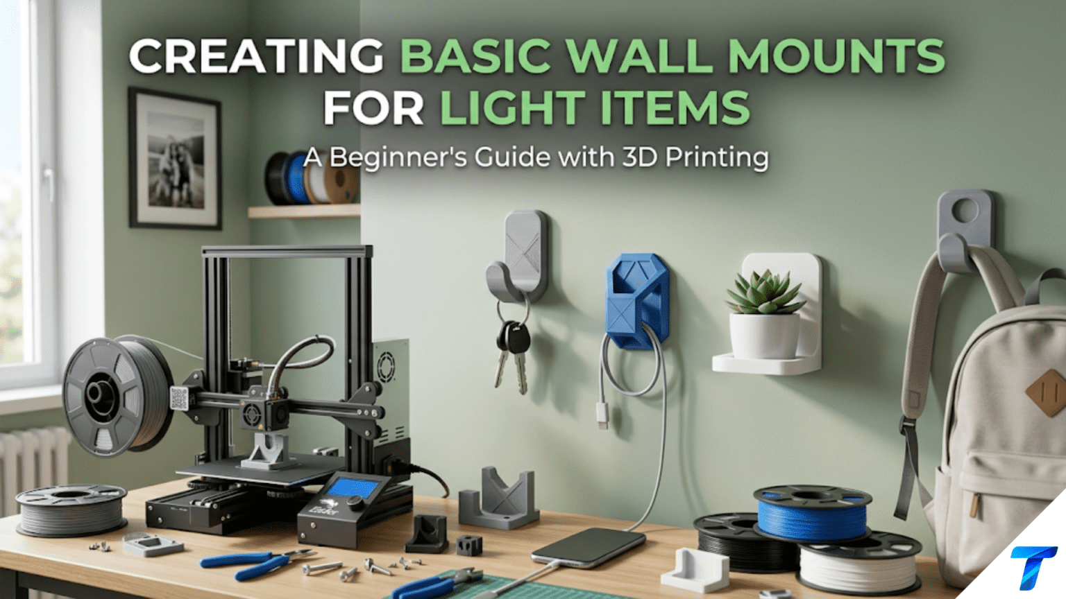
3D printed wall mounts are custom-designed brackets, hooks, clips, and holders that attach to walls and hold specific items — from headphones and remote controls to cables, small tools, and decorative objects. They are among the most practically transformative home printing projects because they move items off surfaces and onto walls, freeing desk and counter space while keeping frequently used items immediately accessible. Designing a wall mount introduces load-bearing design principles, mounting hardware selection, and the discipline of designing for a specific wall type and fastener system.
Introduction: Reclaiming Surface Space
Every flat surface in a home has a natural tendency to fill. Desks accumulate devices, cables, accessories, and objects. Counters collect appliances, tools, and everyday-use items. Shelves become staging areas for things that need a temporary place and stay permanently. The floor around furniture becomes a graveyard of items that have nowhere else to go.
Wall space, by contrast, is almost universally underutilized. In most homes and offices, the walls between furniture hold nothing — they are vertical planes of empty potential that could be holding, displaying, and organizing the items that currently clutter the horizontal surfaces.
3D printed wall mounts bridge this gap with a specificity that commercial solutions cannot match. A commercial wall mount is designed for a hypothetical average item — a general-purpose hook, a standard bracket, a generic cable clip. A printed wall mount is designed for your specific item, your specific wall surface, your specific spatial requirements, your specific aesthetic preferences.
The headphone hook that cradles your exact headphone model at the exact height that keeps the cord from dragging on the desk. The remote control holder that mounts beside your TV at the precise position where your hand naturally reaches for it. The cable management clip that fits the specific cable diameter of the power brick you need to tuck behind your monitor. These solutions don’t exist commercially because they’re too specific. Your printer makes them possible.
This guide covers the complete workflow for wall mount printing: the physics of wall mounting (load, moment, and the forces that make mounts fail), wall type considerations and appropriate fastener systems, design principles for load-bearing mounted brackets, material selection, slicer settings for structural parts, and a comprehensive catalog of specific wall mount projects worth building.
The Physics of Wall Mounting: Why Mounts Fail
Understanding why wall mounts fail — and designing to prevent it — is the most important knowledge in this article. A wall mount that falls damages the item it was holding, damages the wall, and potentially injures anyone in the way.
The Forces on a Wall Mount
When an item hangs from a wall mount, it creates several forces that the mount must resist:
Downward load (gravity): The weight of the item pulling straight down. This is the most obvious force. A 500g set of headphones exerts 0.5kg × 9.8m/s² ≈ 5 Newtons of downward force.
Bending moment: Because the item hangs at some distance from the wall (the mount’s projection), gravity creates a rotational force at the mount’s attachment point. A 500g item hanging 80mm from the wall creates a bending moment of 0.5kg × 0.08m = 0.04 N·m at the wall face. This moment tries to peel the mount away from the wall at the top while pushing the bottom against the wall.
Shear force: The downward weight of the item creates a shear force on the screws — they’re being pushed sideways (downward) through the wall. This is usually well within the capacity of standard screws in appropriate anchors.
The bending moment is the most important force to design against. It is what causes mounts to fail — not because the screws can’t hold the weight, but because the torque at the mounting point eventually works the fasteners loose or breaks the mount at the wall interface.
The Lever Effect
The longer the mount’s horizontal projection (how far the item hangs from the wall), the larger the bending moment for any given weight. A 500g item hanging 40mm from the wall creates half the bending moment of the same item hanging 80mm from the wall.
Design implication: Keep projection distances as short as practical. Design mounts that hold items close to the wall rather than far from it. Every extra millimeter of projection multiplies the stress on the mounting point.
Designing Against the Bending Moment
The bending moment is resisted by:
Mount thickness and area at the wall: A larger contact patch between the mount and the wall distributes the bending moment over more area. A mount with a wide backing plate (80mm × 80mm) handles the moment better than one with a narrow backing strip (20mm × 80mm).
Screw spacing: Two screws spaced far apart create a longer lever arm that opposes the bending moment more effectively than two screws close together. For a 120mm wide mounting plate, screws at 80mm apart are significantly more effective than screws at 40mm apart.
Mount geometry: Mounts with a triangular gusset (a diagonal bracing element between the projecting arm and the wall plate) handle bending moments much more efficiently than L-shaped brackets without gussets. The gusset creates a triangle, which is the strongest geometric shape for resisting this type of loading.
What “Light Items” Means
This article is scoped to light items — generally under 1–2kg. This covers:
- Headphones (200–500g)
- Remote controls (100–200g)
- Small tablets (300–600g)
- Cables and cable management (negligible weight)
- Small tools (100–500g)
- Decorative objects (100–500g)
For items over 2kg (heavy tools, speakers, monitors), printed mounts are not appropriate without specific engineering analysis. Use commercial hardware designed for the load, or heavy-duty printed mounts with metal reinforcement.
Wall Types and Fastener Systems
The wall type determines which fasteners are appropriate. Using the wrong fastener for the wall type is the most common cause of wall mount failure.
Drywall (Most Common in North America)
Drywall (gypsum board) is soft and does not hold screws well without additional anchors — unless the screw reaches a wood stud behind the drywall.
Into a stud (strongest): Use wood screws (#8 or #10, 38–50mm long) driven into a stud located with a stud finder. Stud connections are extremely strong and appropriate for any light item mount. Studs are typically spaced 400mm or 600mm apart.
Toggle bolts / butterfly anchors: For locations without a stud, toggle bolts pass through the drywall and open a wing behind it, distributing load over a larger area. Appropriate for light loads (under 5kg per anchor) when studs are not accessible.
Self-drilling drywall anchors: Plastic anchors that screw directly into drywall without drilling. Appropriate for very light loads only (under 2kg per anchor). Not recommended for anything that experiences dynamic loading (being touched, items being removed and replaced).
Adhesive mounting (Command strips): Appropriate only for very light items (under 2kg) in low-vibration environments. Follow manufacturer instructions exactly — surface must be perfectly clean and dry, adhesive must cure 24 hours before loading.
Plaster Walls (Older Homes)
Plaster is harder than drywall but more brittle and cracks easily.
Into studs: Same approach as drywall — use a stud finder, drill a pilot hole (plaster cracks without a pilot hole), and drive wood screws into the stud.
Plaster anchors: Specialized expansion anchors designed for plaster. Do not use standard drywall anchors in plaster — they will crack the plaster.
Brick and Masonry
Masonry anchors: Use a hammer drill with a masonry bit to drill into the mortar (not the brick face when possible) and insert expansion anchors sized for the screw you’re using.
Pilot hole size matters: Always use the correct drill bit diameter for the specific anchor — too small and the anchor won’t insert; too large and it won’t expand properly.
Tile
Drilling into tile without cracking it requires carbide-tipped tile drill bits and low speed. Alternatively, command strips or suction cup mounting avoids drilling entirely for light items.
Design Principles for Wall Mounts
The Mounting Plate: The Foundation of Every Mount
The mounting plate is the flat section of the wall mount that contacts the wall surface and contains the screw holes. Every design principle for wall mounts starts here.
Plate size: Larger is stronger. A 100mm × 80mm plate is significantly more stable than a 50mm × 40mm plate for the same screw locations, because the wider base resists tilting.
Screw hole placement:
- Minimum 2 screws for any mount bearing significant load
- Space screws as far apart as possible within the plate dimensions
- Keep at least 10mm of material between the screw hole edge and the plate edge
- Countersink screw holes (90° countersink to the correct diameter for your screw head) so screw heads sit flush with or below the plate surface
Plate thickness: Minimum 5mm for a functional wall mount plate. The plate must resist bending as the bending moment tries to pull the top away from the wall. 6–8mm provides better rigidity.
Wall contact surface: The plate surface that contacts the wall must be flat and smooth for full-surface contact. If the plate warps during printing, it won’t sit flush against the wall, which reduces stability and looks poor.
The Projection Arm: The Bridge From Wall to Item
The projection arm extends from the mounting plate to the item-holding feature (hook, shelf, cradle). This is where the bending moment is most critical.
Triangular gusset design: The most structurally efficient design adds a triangular gusset — a diagonal support element — between the underside of the projection arm and the mounting plate. This gusset converts the bending moment into compression and tension within the triangle, which materials resist much better than unsupported bending.
In Tinkercad, a gusset is simply a triangular wedge positioned at the junction between the arm and the plate.
Arm cross-section: The arm should be at least 8mm × 8mm in cross-section for any load-bearing application. Deeper (taller) arms are stiffer in the bending direction.
Arm length (projection): Keep as short as practical. If the item being held only needs 40mm of projection, don’t design 80mm. Every extra millimeter of arm length increases the bending moment proportionally.
Print Orientation for Maximum Strength
Print orientation critically affects wall mount strength:
Mounting plate flat on the build plate: This places the layer lines running horizontally across the plate. The bending moment at the plate/arm junction tries to pull layers apart in tension on the top of the junction and compress them on the bottom. With layers horizontal, the bottom of the mount (in compression) is strong; the top (in tension along layer boundaries) is the weak point.
Arm extending upward from the plate: With the mount printed in typical orientation, the arm grows upward during printing. The load from the hanging item creates shear in the arm’s layer planes — layers sliding past each other — which is stronger than tension pulling them apart.
Alternative orientation: For some mount designs, printing at 90° (arm pointing down on the plate, then stood on end) places layers running along the arm’s long axis. In this orientation, the downward load from the item is entirely compressive along the layers — the strongest possible direction. The tradeoff is that the wide mounting plate now prints vertically and may require support.
For most practical wall mounts, the standard orientation (plate flat, arm vertical) is a good compromise between print ease and strength.
Specific Wall Mount Projects
Headphone Holder
One of the most popular wall mount prints. Headphones are bulky objects that clutter desks when not in use and need to hang when stored.
Design specifications:
- Hook profile: Should match the headband curvature of your specific headphones — typically a gentle curve 20–30mm across, 15–20mm deep (front to back), 10–15mm wide
- Headband capture: A slight concavity or lip on the hook prevents headphones from sliding off
- Height: Position the hook so the earpieces hang clear of the desk surface (typically 200–300mm above desk level)
- Load: 200–500g — light load, but dynamic (headphones are placed and removed frequently)
Design in Tinkercad:
- Create mounting plate: 80mm × 70mm × 6mm
- Create vertical riser: 80mm × 10mm × 200–300mm (height depends on desk clearance)
- Create projection hook: A curved arm 60–80mm long, 10mm wide, shaped to match headband curvature
- Add triangular gusset at the hook-riser junction
Placement considerations: Mount the hook above the desk, positioned so the headphone cord falls clear of the desk surface when hanging.
Remote Control Holder
A wall-mounted pocket that holds a remote control (or multiple remotes) beside the TV or entertainment center.
Design specifications:
- Interior dimensions: Match your specific remote (measure width × depth + 5mm clearance each dimension; height = 50–70% of remote length to hold securely while allowing easy withdrawal)
- Tilt angle: 5–15° forward tilt makes the remote’s top accessible while keeping it contained
- Material: PLA acceptable — remote controls are very light (100–200g)
- Multiple remotes: Design adjacent pockets of appropriate widths for each remote in your collection
The multiple remote challenge: Most households have 3–5 remote controls of different sizes. A custom holder with individual pockets sized for each specific remote completely solves the “where is the remote?” problem while keeping all remotes organized and accessible.
Cable Management Clips
Simple clips that attach to a wall surface and route cables cleanly — power cables, Ethernet cables, USB cables — along wall edges, behind furniture, and between devices.
Design specifications:
- Clip opening: Cable diameter + 1–2mm (tight enough to grip; loose enough to allow easy routing and removal)
- Wall attachment: Single screw through a small plate, or adhesive-backed for clean installation
- Cable retention: A slight narrowing at the clip opening (less than the cable diameter) creates a snap-fit that holds cables in place
Cable clip varieties:
- Round cable clips: For single round cables. Fastest to design — just a C-shaped profile with a mounting flange.
- Flat cable clips: For flat cables (USB-A, ribbon cables, flat speaker wire)
- Multi-cable clips: Side-by-side channels for running multiple cables together
- Corner clips: Designed to hold cables at 90° turns along wall corners
Key Holder
A wall-mounted hook or hooks specifically for keys — the classic “key hook by the door” that prevents the daily “where are my keys?” problem.
Design: A mounting plate with multiple hooks projecting from it, each hook sized to accept a standard key ring. Hooks should be approximately 15mm long and 5mm diameter to accept standard key rings freely.
This was covered in depth in Article 69 (key holders and key tags) — reference that article for detailed design specifications.
Phone Charging Station / Wall Dock
A wall-mounted dock that holds a phone in a specific orientation while charging — portrait or landscape, at a specific angle for use as an alarm clock, bedside reference, or kitchen display.
Design specifications:
- Phone cradle: Sized for the specific phone model (reference Article 77 on phone case design for dimension guidance)
- Cable routing: An integrated channel or recess for the charging cable to enter cleanly from below or behind the phone
- Viewing angle: 70–80° from horizontal for a bedside clock orientation; 30–45° for active use (recipe viewing, navigation)
- Height: At appropriate reading height for the intended use
Mail and Document Organizer
A wall-mounted organizer for incoming mail, documents, and papers — typically mounted near the front door or home office entry. Multiple slots or compartments organized by category (to sort, to file, to respond).
Design:
- 3–4 vertical slots, each 10–15mm wide and deep enough for standard document paper (230mm wide × A4 or Letter height)
- Mounting plate across the top with screws into studs
- Each slot slightly angled forward (documents lean toward you for easy retrieval)
- Label area on each slot for category identification
Material Selection for Wall Mounts
| Material | Load Capacity | Indoor Use | Notes |
|---|---|---|---|
| PLA | Adequate for < 200g | Good | Acceptable for very light items only; creep under sustained load |
| PETG | Good for < 1kg | Excellent | Recommended default for all indoor wall mounts |
| ASA | Excellent for < 1.5kg | Excellent | Better for garage and utility spaces |
| Nylon | Excellent | Good | Premium for high-cycle, high-load mounts |
| PLA+ | Marginal improvement | Good | Not significantly better than PLA for load-bearing |
The PLA Warning for Load-Bearing Mounts
PLA’s creep behavior — its tendency to slowly deform under sustained load — makes it problematic for wall mounts that hold items continuously. A PLA headphone hook might work perfectly for months and then slowly sag as the material creeps under the constant weight of the headphones. The deformation is gradual and may not be noticed until the hook has sagged noticeably or the item has fallen.
For any wall mount holding items continuously (not occasionally), use PETG. The improved creep resistance of PETG makes it significantly more reliable for load-bearing applications.
Slicer Settings for Wall Mounts
Wall mounts prioritize structural integrity over surface aesthetics.
| Setting | Recommended Value | Notes |
|---|---|---|
| Layer Height | 0.2mm | Standard; prioritize strength |
| Print Speed | 40–50 mm/s | Moderate for good layer fusion |
| Outer Wall Speed | 25–30 mm/s | Adequate outer wall quality |
| Perimeters/Walls | 5–6 | Critical for mounting plate and arm strength |
| Infill | 40–50% | High infill for structural mounts |
| Infill Pattern | Gyroid | Isotropic strength in all directions |
| Top/Bottom Layers | 5 | Standard closure |
| Support | As needed | Avoid on critical load-bearing surfaces |
| Cooling | 70–80% PETG | Reduced for better layer adhesion |
| Temperature (PETG) | 240–245°C | Upper range for maximum layer fusion |
| Bed Adhesion | Brim (8–10mm) | Wide brim for large mounting plates |
Why 5–6 Perimeters for Wall Mounts
Wall mounts experience forces primarily at their outer surfaces — the mounting plate’s back face in compression, the plate’s top edge in tension, the arm’s surfaces in bending. Increasing perimeters to 5–6 means more material at the outer zones where stress concentrates, significantly improving the mount’s load-bearing capacity without dramatically increasing print time.
For a wall mount that will hold items continuously over months or years, the 5-minute difference in print time that comes from adding 2 extra perimeters is among the best investments you can make in the print’s durability.
Step-by-Step: Designing and Installing a Headphone Wall Mount
Step 1: Measure Your Headphones
Measure:
- Headband cross-section at the top (width and depth of the band where it will rest on the hook)
- Headband curvature radius (approximately) — hold a ruler against the inside of the headband arc
- Weight — weigh on a kitchen scale
- Earpiece diameter — determines minimum hook-to-wall clearance (earpieces must not contact the wall)
Step 2: Determine Hook Dimensions
Based on measurements:
- Hook cross-section: 15mm wide × 10mm deep
- Hook projection from wall: Earpiece diameter ÷ 2 + 15mm clearance (e.g., for 90mm diameter earpieces: 45mm + 15mm = 60mm projection)
- Hook curvature: Match headband radius — a gentle curve rather than a sharp angle
- Hook length: 40–60mm (enough to cradle the full headband width)
Step 3: Design in Tinkercad
- Mounting plate: 90mm × 80mm × 7mm
- Vertical riser: Rising from the plate to the appropriate height (typically 200–250mm above desk surface)
- Hook arm: Extending horizontally from the top of the riser, curved to match headband geometry
- Gusset: Triangular support between the underside of the hook arm and the riser/plate, 15mm deep at its base
- Screw holes: Two countersunk holes in the mounting plate, spaced 60mm apart vertically
Export as STL.
Step 4: Slice with Strength Settings
- 0.2mm layer height
- 5 perimeters
- 45% Gyroid infill
- PETG at 242°C / 80°C bed
- 75% cooling
- Wide brim (10mm)
- Mounting plate flat on build plate
Step 5: Print and Inspect
Print time: 1.5–2.5 hours. Inspect:
- No delamination at hook-riser junction
- Gusset is fully solid with no voids
- Mounting holes are clean and correct diameter
- Hook curve is smooth and consistent
Step 6: Find Stud and Mount
- Use a stud finder to locate studs at the intended mount location
- Mark the stud center
- Hold the mount in position and mark screw hole positions
- Drill pilot holes 2mm diameter at the marked positions
- Drive #8 wood screws (40mm long) through the mount holes into the studs
- Do not overtighten — tighten until firm contact, then one additional quarter turn
Step 7: Load Test
Before hanging valuable headphones, test the mount by applying downward force (pull down on the hook with 5–10× the headphone weight). If the mount holds without movement or creaking, it’s properly installed.
Step 8: Hang Headphones
Hang headphones and verify:
- Headphones rest securely without rocking
- Earpieces clear the wall surface
- Cable hangs freely without strain
- Height is appropriate for easy reach from the desk
Troubleshooting Common Wall Mount Issues
Mount Cracks at the Arm-Plate Junction
Cause: Insufficient material at this high-stress point; wrong print orientation concentrating stress at layer boundaries; PLA creep failure under sustained load.
Solution: Redesign with a triangular gusset at the junction. Increase perimeters to 6. Switch to PETG. Ensure print orientation places this junction’s critical stress direction parallel to layer lines.
Mount Pulls Away From Wall Over Time
Cause: Fasteners are in drywall without stud engagement; bending moment working fasteners loose gradually; adhesive bond failing.
Solution: Relocate to a stud position using a stud finder. If studs are not accessible, use proper toggle bolts rather than basic drywall anchors. For adhesive mounts, replace with screw mounting — adhesive is not appropriate for mounts experiencing frequent use or significant loads.
Hook Slowly Deforms (Sags) Over Months
Cause: PLA creep under sustained load; temperature in the room occasionally approaching PLA’s softening point.
Solution: Reprint in PETG. PETG’s better creep resistance prevents this deformation under typical indoor conditions. For warm environments (near south-facing windows, in warm climates), use ASA which has even better temperature resistance.
Mount Looks Good But Vibrates or Rattles Against Wall
Cause: Mounting plate is not flush against the wall surface (slight warp in the print); fasteners are not tight; the plate’s contact surface area is too small.
Solution: Add adhesive-backed rubber feet or foam tape strips to the back of the mounting plate — these fill any gap between the plate and wall, eliminate rattle, and protect the wall surface from scratches. Slightly tighten the mounting screws (but do not overtighten — this can crack the plate).
Item Keeps Sliding Off the Hook
Cause: Hook profile doesn’t match the item’s hanging point; insufficient depth or curvature on the hook; item is top-heavy and unstable on the hook.
Solution: Redesign the hook with a deeper cup profile that captures the item more securely. Add a small lip or retention feature at the end of the hook. Consider a two-point support rather than a single hook for top-heavy items.
Building a Wall Organization System
Individual wall mounts are useful; a coordinated wall organization system transforms a room’s functionality. Consider a systematic approach:
Audit the surfaces: Identify which horizontal surfaces in each room are most cluttered. These are the priority rooms for wall mounting projects.
Map the wall: Identify available wall space near each cluttered surface — studs, available area, appropriate heights for the specific items.
Design for consistency: All mounts in a room printed in the same material and color create a more deliberate, organized appearance. Matte black PETG throughout a home office, natural wood-fill in a kitchen — consistent material language ties the organization system together.
Install progressively: Start with the highest-value mount (the item that causes the most frustration when displaced), verify success, then continue. Each successful mount builds confidence and skill for the next.
Over time, a room with a well-designed wall organization system feels qualitatively different from one without — more spacious, more calm, and functionally better organized for how people actually use it.
Conclusion: The Walls Are Working Now
Most homes treat walls as passive surfaces — backgrounds for furniture and artwork, surfaces that separate rooms but do little functional work of their own. This is a significant waste of the most abundant organizational resource in any room.
Your printer changes this. Every vertical surface becomes a potential site for an organized, functional wall-mounted solution. Every item that currently sits on a horizontal surface consuming space, waiting to be misplaced or knocked over, can have a wall home instead.
The headphone hook. The remote pocket. The cable management system. The key holder by the door. Each one small individually. Together, they transform how a space functions and how it feels to inhabit it.
Print with PETG. Design with the gusset. Mount into studs. Build your wall system one piece at a time.
The walls are waiting.