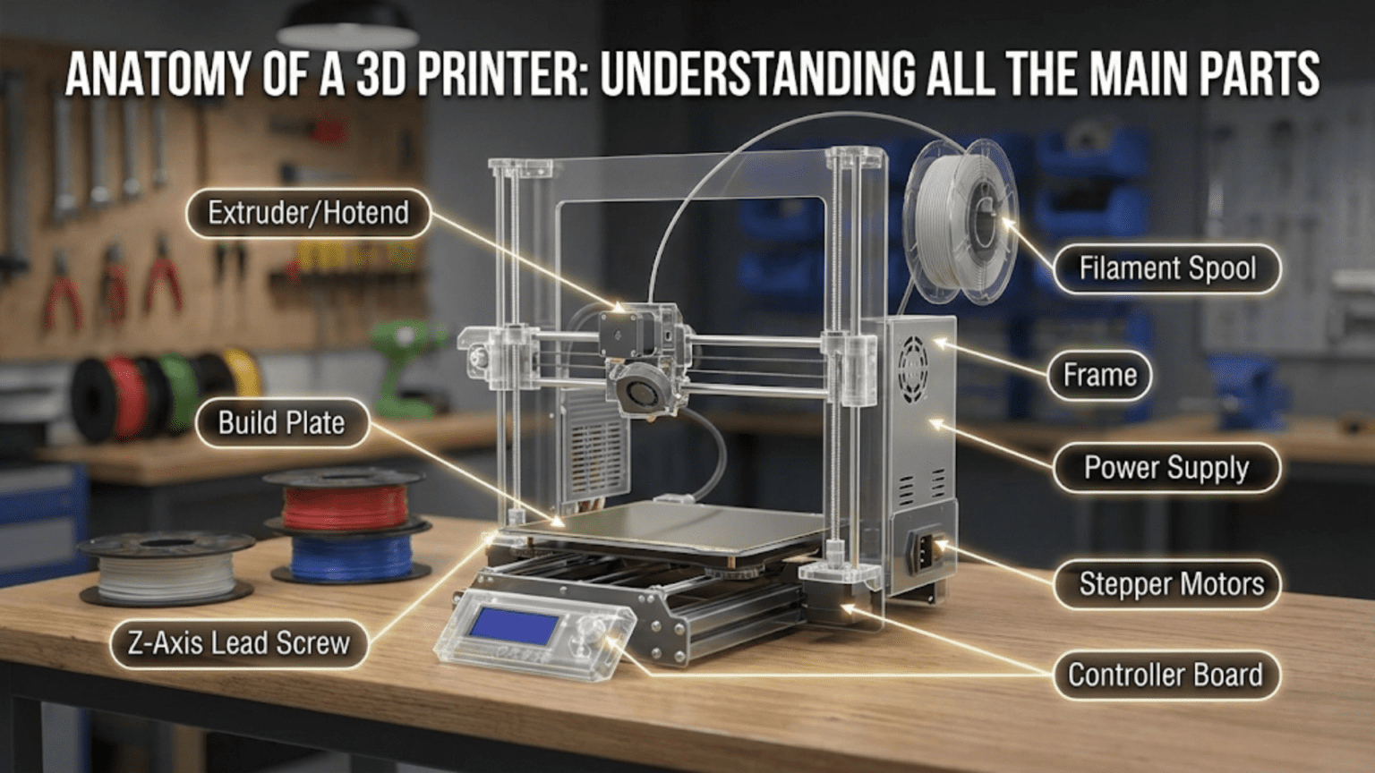
A 3D printer consists of several interconnected mechanical, electrical, and thermal components working together to transform digital designs into physical objects. The main parts include the frame (structural foundation), motion system (motors, belts, and rails), extruder assembly (filament feeding mechanism), hotend (melting chamber), build plate (printing surface), electronics (mainboard and sensors), and power supply, each playing a specific role in the additive manufacturing process.
Introduction
When you first look at a 3D printer, it might seem like a complex tangle of motors, wires, and mysterious components. However, once you understand the anatomy of these machines, they become remarkably logical systems where each part serves a specific purpose in the printing process. Whether you’re considering purchasing your first printer, troubleshooting an existing one, or simply curious about how these fascinating devices work, understanding the main components is your foundation for success.
In this comprehensive guide, we’ll dissect a typical FDM (Fused Deposition Modeling) 3D printer, examining each major component, explaining its function, and showing how all the parts work together. By the end, you’ll have a complete mental map of what’s happening inside your printer every time you press “print.”
The Fundamental Structure: Understanding the Framework
The Frame System
The frame serves as the skeleton of your 3D printer, providing structural support for all other components. Think of it as the foundation of a building—if the foundation isn’t solid and stable, everything built upon it will have problems.
Most modern consumer 3D printers use aluminum extrusion frames. These are prefabricated aluminum profiles with precisely machined channels that allow for easy assembly and mounting of components. The most common type is 2020 aluminum extrusion (20mm x 20mm cross-section), though larger printers may use 3030, 4040, or even larger profiles for increased rigidity.
The frame’s quality directly impacts print quality. A wobbly or flexible frame introduces vibrations during printing, which appear as artifacts called “ringing” or “ghosting” in your prints. When motors accelerate and decelerate, any frame flex gets translated into slight position errors that show up as surface imperfections.
Frame designs typically fall into three categories:
Cartesian frames arrange the axes in a traditional X, Y, and Z configuration. The Prusa i3 design, one of the most popular frame styles, uses this approach with the Y-axis moving the bed forward and backward, the X-axis moving the hotend left and right, and the Z-axis raising and lowering the X-axis gantry.
CoreXY frames use a more complex belt arrangement where two motors work together to control both X and Y movements. This design keeps heavy motors stationary on the frame rather than moving them during printing, allowing for faster, more accurate prints with reduced weight on the moving components.
Delta frames use a completely different approach with three vertical arms that move up and down, suspending the hotend on cables or rods. The mathematics controlling the three arms’ coordinated movement create circular patterns rather than linear ones.
The material choice matters significantly. Steel frames offer maximum rigidity but add weight and cost. Acrylic frames were common in early consumer printers but flex too easily for precision work. Aluminum extrusion provides an excellent balance of strength, weight, and cost, explaining its dominance in the market.
Mounting Points and Connectors
The frame isn’t just about the main beams. Throughout the structure, you’ll find various mounting points where components attach. T-nuts slide into the channels of aluminum extrusion, providing adjustable mounting points. Corner brackets strengthen the joints where frame pieces meet at right angles.
Some printers include cable management features built into the frame design, with channels for routing wires safely away from moving parts. Others add zip-tie points or clips to organize the wiring harness.
The rigidity at connection points requires attention. Many printer builders add extra bracing with diagonal supports or corner reinforcements to minimize frame flex. The stiffness of these connections determines how well the printer maintains dimensional accuracy during aggressive printing movements.
The Motion System: Creating Controlled Movement
Stepper Motors
Stepper motors represent the muscle of your 3D printer. Unlike standard DC motors that spin continuously, stepper motors move in precise incremental steps. This stepping action allows the printer’s electronics to control position without requiring feedback sensors.
A typical FDM printer uses four to five stepper motors. Two control the Z-axis (vertical movement), one controls the X-axis, one the Y-axis, and one drives the extruder. Some advanced printers double up motors on certain axes for added power or to drive dual Z-axis lead screws simultaneously.
The most common stepper motor in consumer 3D printers is the NEMA 17 standard. This designation refers to the motor’s mounting face dimensions (1.7 inches square). Within this standard, motors vary by torque rating and physical length. A longer motor typically provides more torque but also more weight.
Stepper motors work by energizing electromagnetic coils in sequence, causing an internal rotor to step to specific positions. Most 3D printer steppers have 200 steps per full rotation, meaning each step moves 1.8 degrees. However, the driver circuits can subdivide these steps (called microstepping) to achieve smoother movement and finer positioning.
The holding torque specification indicates how much rotational force the motor can resist when powered. For extruders pushing filament through restrictive nozzles, adequate holding torque prevents skipped steps. For axis movement, the motor needs enough torque to overcome the inertia of the moving components plus any friction in the motion system.
Modern stepper drivers like the Trinamic TMC2208 or TMC2209 include features that make motors run quieter by adjusting the current waveform and implementing stealthChop technology. These drivers can reduce the characteristic stepper motor noise from a loud buzz to a barely audible hum.
Belts and Pulleys
For the X and Y axes, most printers use timing belts to convert the stepper motor’s rotational movement into linear motion. GT2 belts have become the standard, featuring a 2mm pitch (distance between teeth) that meshes with matching pulleys on the motor shafts.
Belt quality matters more than many beginners realize. Cheap belts stretch over time, leading to dimensional inaccuracy. High-quality reinforced belts use fiberglass or steel cores that resist stretching while maintaining flexibility. The rubber compound should be durable enough to withstand millions of movement cycles without wearing down the teeth.
Pulleys come in various tooth counts, most commonly 16 or 20 teeth. The tooth count affects the balance between torque and speed. A smaller pulley moves less distance per motor rotation but provides more mechanical advantage for the motor. Larger pulleys cover more distance per rotation but require more motor torque.
Belt tension represents a critical adjustment. Too loose, and the belt can skip teeth on the pulley, causing layer shifts in your prints. Too tight, and you increase wear on motor bearings while adding resistance that makes motors work harder. Proper tension allows a slight deflection when pressed but maintains firm engagement with the pulley teeth.
The belt routing path should minimize the number of direction changes and avoid crossed belts that create friction. CoreXY systems use complex belt paths with multiple idler pulleys to achieve their motion characteristics, requiring careful attention to belt routing during assembly.
Linear Motion Components
To achieve straight, smooth movement, 3D printers use various linear motion systems. These guide the toolhead, bed, or other moving components along precise paths.
Linear rods were the dominant solution in early consumer printers. Hardened steel rods, typically 8mm or 10mm in diameter, serve as rails along which linear bearings slide. LM8UU bearings (linear motion, 8mm, ultra-ultra short) are common choices, containing recirculating ball bearings that roll along the rod surface.
The quality of linear rod systems depends heavily on rod straightness and bearing quality. Bent rods create binding points where the carriage sticks, causing print defects. Cheap bearings with inadequate precision leave slop in the system, reducing positional accuracy.
Linear rails have become increasingly popular in modern printer designs. These use a profiled rail with a matching carriage containing recirculating ball bearings. MGN series linear rails (miniature guide rail, narrow) are common, with MGN12 being a popular choice for medium-sized printers.
Linear rails offer several advantages over rods. The wider bearing surface provides more support, reducing cantilever deflection when the toolhead extends far from the support point. The preload on linear rails can be adjusted or specified at purchase, allowing you to balance smoothness against rigidity. Multiple rows of ball bearings share the load, increasing longevity.
However, linear rails cost more and require flatter mounting surfaces than rods, which can mount with simple clamps. The precision machining required for linear rail systems adds complexity to printer design.
V-slot wheels represent another approach, common in designs like the Ender 3. These use polyurethane or delrin wheels running in V-shaped grooves cut into aluminum extrusion. Three wheels contact the V-groove at specific angles, providing constraint in multiple directions.
V-slot systems offer low cost and quiet operation. The wheels absorb some vibration, potentially improving print quality in certain scenarios. However, they require regular maintenance as the wheels wear over time. Proper eccentric nut adjustment ensures the wheels maintain appropriate contact pressure without being too tight.
Lead Screws and Z-Axis Motion
Most FDM printers move the Z-axis using lead screws—threaded rods that convert rotational motor movement into vertical linear motion. Standard lead screws have an 8mm diameter with either 2mm or 8mm lead (the distance traveled per full rotation).
A 2mm lead screw moves very slowly, providing excellent resolution for the Z-axis. Each full step of a 200-step motor moves only 0.01mm—far finer than most prints require. This gearing down also increases the motor’s effective force, allowing it to lift heavy bed assemblies easily.
An 8mm lead screw sacrifices some resolution for faster Z-axis movement. For large prints requiring hundreds of millimeters of Z travel, the faster movement speeds up the overall print time. The resolution remains adequate for typical layer heights.
Lead screw quality varies significantly. Cheap screws may not be perfectly straight, causing Z-axis wobble that appears as regular wavy patterns in vertical walls. Better screws undergo precision machining and straightness testing. Some high-end printers use ball screws instead of lead screws, employing recirculating ball bearings for reduced friction and backlash.
The lead screw nut interface matters as well. Basic brass nuts work but can develop backlash (play in the threads) over time. Anti-backlash nuts use spring-loaded designs to eliminate this play. For applications requiring exceptional precision, some builders use POM (polyoxymethylene) nuts that combine low friction with good wear resistance.
Z-axis coupling between the motor shaft and lead screw requires flexibility to prevent binding. Rigid couplers transfer any motor shaft misalignment directly to the lead screw, potentially causing binding or uneven layers. Flexible couplers or oldham couplings allow slight misalignment while still transmitting rotational force effectively.
The Extruder Assembly: Feeding Filament to the Hotend
Extruder Motor and Gear System
The extruder motor controls the rate at which filament feeds into the hotend. This motor faces unique challenges—it must maintain consistent pressure while gripping a round, sometimes slippery filament material and pushing it through significant resistance.
Most extruders use a gear reduction system to increase the motor’s effective force. The motor drives a small gear that meshes with a larger gear, providing mechanical advantage. Common gear ratios range from 3:1 to 5:1, with some specialized high-flow extruders using even higher ratios.
The drive gear contacts the filament, gripping it with sharp teeth that bite into the material. Dual-gear extruders add a second gear opposite the drive gear, creating a dual-grip system that applies pressure from both sides. This design reduces the chance of filament slipping and allows the motor to exert more force without crushing the filament.
The tension adjustment mechanism controls how hard the gears press against the filament. Too little tension, and the filament slips when resistance increases. Too much tension, and the gears can deform the filament, creating an inconsistent diameter that causes extrusion problems. Some extruders use adjustable springs, while others employ set screws or cam mechanisms for tension control.
Bowden vs. Direct Drive Configurations
The relationship between the extruder motor and hotend defines two main configuration types.
Bowden extruders mount the motor and drive gear on the printer frame, using a PTFE (Teflon) tube to guide filament from the extruder to the hotend. This separation keeps the heavy motor stationary while allowing the lighter hotend to move freely. The reduced moving mass enables faster printing speeds and simpler mechanical designs.
However, Bowden systems introduce challenges. The tube creates friction that the extruder must overcome. More significantly, the tube’s compressibility makes retraction less precise. When you want to pull filament back slightly to prevent oozing, the tube’s flex absorbs some of the movement before it reaches the hotend. This makes flexible filaments nearly impossible to print successfully with Bowden systems.
Direct drive extruders mount the motor directly on the moving carriage, positioning it immediately above the hotend. This configuration eliminates the PTFE tube, providing direct control over filament movement. Retractions become much more responsive, and flexible filaments print reliably.
The tradeoff involves increased moving mass. The motor adds weight that the X and Y motors must accelerate and decelerate with each direction change. This limits practical printing speeds and can introduce artifacts if the printer’s motion system can’t handle the added mass. However, modern lightweight designs using pancake motors (short NEMA 17 motors) have minimized this disadvantage significantly.
Filament Path and Guides
The path filament follows from the spool to the hotend requires careful attention. Poor filament routing can add friction, cause tangles, or create binding that leads to print failures.
Filament guides align the filament entering the extruder, preventing it from feeding at odd angles that could cause grinding or slipping. These guides might be simple printed parts or precision-machined components depending on the printer’s quality level.
For Bowden systems, the PTFE tube requires support at both ends. Pneumatic couplings grip the tube, securing it in place while allowing easy removal for maintenance. The tube must be cut cleanly and squarely—angled cuts create gaps where filament can catch or ooze.
Some printers include filament sensors along the path. These sensors detect when filament runs out or snaps, automatically pausing the print so you can reload material and resume. More advanced sensors monitor filament movement, detecting clogs or jams before they ruin your print.
The spool holder itself affects filament feeding. A poorly designed holder that allows the spool to wobble or introduces excessive friction makes the extruder work harder. Ball-bearing spool holders minimize friction, while spool holders mounted away from the printer reduce vibration transfer from the spinning spool.
The Hotend: Where Melting Happens
Heat Break and Thermal Barrier
The hotend’s primary job involves melting filament in a controlled manner, but equally important is keeping the melting zone precisely defined. The heat break accomplishes this critical function.
This component separates the hot zone (where melting occurs) from the cold zone (where solid filament remains). Made from materials with poor thermal conductivity—typically stainless steel or titanium—the heat break limits heat transfer upward while still providing structural strength to hold the hotend together.
The heat break’s geometry features a thin-walled section that minimizes the cross-sectional area for heat conduction. Some advanced heat breaks incorporate additional features like internal grooves that increase surface area for the cooling air while maintaining minimal thermal conductivity.
Inside the heat break, the filament must travel smoothly without catching. Any internal steps or rough surfaces create opportunities for molten filament to stick and cause jams. Quality heat breaks feature precision-machined internal diameters with smooth finishes.
The transition point where the heat break meets the heater block represents a critical junction. This joint must be sealed to prevent molten filament from leaking out while maintaining good thermal isolation. PTFE-lined hotends extend a PTFE tube through the heat break all the way to the nozzle, providing a slippery surface for filament travel. All-metal hotends eliminate the PTFE, allowing higher temperature operation at the cost of requiring more precise manufacturing.
Heater Block and Heating Element
The heater block provides the mass and heat capacity to maintain stable temperatures during printing. Typically machined from aluminum for its excellent thermal conductivity, the heater block accepts the heating element, thermistor, nozzle, and heat break.
Heating elements most commonly use resistive cartridge heaters—metal cylinders containing a resistive wire that generates heat when electrical current passes through it. Standard 40-watt cartridge heaters suffice for normal printing, while high-flow applications might use 50 or 60-watt heaters for faster heat recovery.
The heater cartridge inserts into a precision bore in the heater block. A set screw secures it in place, and thermal paste often fills any air gaps to improve heat transfer. The electrical leads connecting to the heater must be strain-relieved to prevent breakage from repeated movement.
Some heater blocks include silicone socks—rubber covers that insulate the block, improve temperature stability, and make cleanup easier when plastic inevitably drips onto the exterior. These socks have openings for the nozzle to extend through while covering the rest of the block.
The heater block’s mass affects thermal performance. Larger blocks heat more slowly but maintain temperature more consistently during printing. Smaller blocks heat quickly but might struggle to maintain temperature during high-flow printing. Volcano and Super Volcano heater blocks extend the length to increase heating capacity for specialized high-speed applications.
Thermistor and Temperature Sensing
Accurate temperature measurement ensures the hotend melts filament properly without overheating. A thermistor—a resistor whose resistance changes predictably with temperature—provides this measurement.
The thermistor (or occasionally a thermocouple in high-temperature applications) inserts into another precision bore in the heater block, positioned as close as practical to the heating element and melt zone. Thermal paste ensures good thermal contact with the block.
The mainboard sends a small current through the thermistor and measures the resulting voltage. Using a lookup table specific to the thermistor type, the firmware converts this voltage reading into a temperature. The NTC 100K thermistor (Negative Temperature Coefficient, 100,000 ohms at 25°C) represents the most common type in 3D printers.
Temperature control uses a PID (Proportional-Integral-Derivative) algorithm that continuously adjusts heater power based on the difference between current and target temperatures. Proper PID tuning prevents temperature oscillation while maintaining responsiveness when conditions change.
The thermistor wiring requires protection since these wires carry low-voltage signals susceptible to electrical interference. Twisted wire pairs help reject noise, and careful routing keeps thermistor wires separated from high-power heater wiring.
Nozzle and Extrusion Orifice
The nozzle represents the final component in the hotend assembly where molten filament exits to form your print. This seemingly simple brass component significantly impacts print quality and capabilities.
Nozzle orifice size determines the width of extruded plastic. Standard 0.4mm nozzles balance detail capability with reasonable print times. Smaller 0.2mm or 0.3mm nozzles produce finer detail but print more slowly. Larger 0.6mm, 0.8mm, or even 1.0mm nozzles enable faster printing of large objects where fine detail isn’t required.
The nozzle’s external geometry matters for print clearance. The cone angle affects how close the nozzle can get to previously printed features. Nozzles with aggressive tapers allow printing steeper overhangs before the nozzle body interferes with already-deposited material.
Material choice determines nozzle longevity and compatibility. Brass offers excellent thermal conductivity and machines easily, making it the standard choice. However, abrasive filaments like carbon fiber or metal-filled materials wear brass quickly. Hardened steel or ruby-tipped nozzles resist wear but conduct heat less efficiently, requiring slight temperature increases. Plated nozzles combine brass’s thermal properties with surface coatings that resist adhesion and wear.
The nozzle threads into the heater block, sealing against the heat break interior to create the melt chamber. Proper nozzle installation requires heating the hotend before tightening to ensure the thermal expansion doesn’t create leaks. The nozzle should seal against the heat break’s interior tube, not bottom out against the heater block threads.
Cooling Fan and Heat Sink
While the heater block needs heat, the area above it must stay cool to prevent premature filament softening. A heat sink with cooling fins extends upward from the heat break, dissipating heat to maintain the temperature gradient.
A small cooling fan, typically 30mm or 40mm, blows air across these fins continuously whenever the hotend operates. This fan runs at full speed regardless of print status since its job involves cooling the heat sink, not the printed part.
The heat sink’s material and design affect cooling efficiency. Aluminum heat sinks with numerous thin fins maximize surface area for heat dissipation. Some designs use heat pipe technology to move heat away from the heat break more effectively.
If this cooling fails, heat creep occurs—heat migrates up the filament, softening it inside the heat break where it should remain solid. The softened filament expands, creating friction that eventually causes a jam. This failure mode explains why hotend fan failures often lead to print failures several layers later when the accumulated heat finally causes jamming.
The Build Plate: Foundation of Every Print
Heated Bed Assembly
The build plate provides the surface where your print adheres during construction. Most modern printers include heated beds that warm this surface to improve adhesion and reduce warping.
The heating element underneath the build surface typically consists of a PCB (printed circuit board) with resistive traces that generate heat when powered. These PCBs are engineered to distribute heat evenly across the bed surface, though perfect uniformity remains challenging, especially on larger beds.
Bed power requirements scale with size. A small 200mm x 200mm bed might use 100-150 watts, while a large 400mm x 400mm bed could require 500 watts or more. This high power draw necessitates robust electrical connections and often requires a separate power supply or a relay to avoid overloading the mainboard.
The relationship between bed size and heating capacity affects warm-up times. Larger beds take longer to reach temperature, though higher wattage heating elements can compensate. Thermal insulation beneath the heating element improves efficiency by directing heat upward toward the print surface rather than wasting it warming the support structure and surrounding air.
Some advanced printers implement multi-zone heating with independent control of different bed regions. This allows printing on one section while another cools, or compensates for uneven heat distribution by adjusting power to different zones.
Build Surface Materials
The material covering the heated bed directly influences how well prints stick during printing and how easily they release when finished.
Glass provides a perfectly flat surface and offers good thermal mass that helps maintain temperature consistency. It works well with glue stick or hairspray as adhesion aids. Glass cleans easily and lasts indefinitely with proper care. However, it requires additional mounting hardware like clips that can interfere with prints near the bed edges.
PEI (Polyetherimide) has become extremely popular as a build surface material. This amber-colored plastic offers excellent adhesion when hot and releases easily when cooled. It works with most common filaments without additional adhesives. PEI surfaces come as sheets that adhere to glass or aluminum beds, or as textured powder-coated surfaces. With care, a PEI surface can last for hundreds of prints.
Textured powder-coated steel sheets provide a textured surface that improves adhesion while leaving a pleasant textured bottom layer on prints. These removable sheets allow you to flex them after printing to pop parts off easily. The magnetic mounting system enables quick surface changes.
BuildTak and similar adhesive surfaces use a textured plastic film that sticks to the bed. They provide strong adhesion but wear out over time and can be difficult to remove when replacement becomes necessary.
The choice depends on your typical materials and preferences. Many users maintain several build surfaces, swapping them for different filament types or finish preferences.
Leveling and Tramming Systems
“Bed leveling” is somewhat of a misnomer—the process actually involves tramming the bed (making it perpendicular to the Z-axis) and establishing its height relative to the nozzle. Regardless of terminology, getting this relationship correct remains crucial for successful first layers.
Manual leveling uses adjustment screws at bed mounting points, typically at the four corners or sometimes three points. You manually adjust these screws while using a piece of paper between the nozzle and bed to gauge the gap. The nozzle should lightly drag on the paper when positioned correctly.
The manual leveling process requires patience and practice. After adjusting one corner, you must recheck the others since adjustments interact—raising one corner can affect the others. Multiple iterations typically achieve acceptable results.
Mesh bed leveling acknowledges that many beds aren’t perfectly flat. The printer probes multiple points across the bed surface, creating a height map. During printing, the firmware adjusts Z-height dynamically based on the X and Y position, compensating for bed irregularities. This software compensation allows successful printing even on slightly warped beds.
Automatic bed leveling adds a probe sensor that measures bed height automatically. Inductive probes detect metal surfaces, capacitive probes work with various materials, and BLTouch devices use a deployable pin. The printer conducts a probing sequence before each print, ensuring accurate compensation even if the bed shifts slightly.
More advanced printers incorporate automated systems that adjust the bed mechanically. Kinematic mounting systems use three precisely located ball-and-cup joints that allow the bed to self-tramming based on probe measurements and automated adjustments.
Electronics and Control Systems
Mainboard and Processor
The mainboard serves as the 3D printer’s brain, controlling all motors, heaters, sensors, and user interface components. Modern mainboards use ARM processors similar to those in smartphones, providing ample computing power for complex calculations.
The mainboard includes stepper motor drivers for each axis and the extruder. Earlier printers used separate driver modules that plugged into sockets, allowing upgrades or replacements. Modern integrated boards incorporate drivers directly onto the mainboard, reducing cost and improving reliability while sacrificing upgrade flexibility.
Driver chips vary in capability and quietness. Older A4988 drivers function adequately but run loudly and lack advanced features. Trinamic TMC drivers add features like stealthChop (for quiet operation), stallGuard (detecting mechanical resistance), and spreadCycle (for higher performance). The TMC2209 represents a popular choice, balancing quiet operation with good performance and reasonable cost.
The processor runs firmware—the software that interprets G-code commands and coordinates all printer functions. Marlin remains the most common firmware for consumer printers, though alternatives like Klipper (which offloads processing to a separate computer) and RepRapFirmware have gained popularity for advanced applications.
Connectivity options on mainboards include USB for direct computer connection, SD card slots for untethered printing, and sometimes WiFi or Ethernet for network printing. The interface choice affects workflow—USB requires a computer to remain connected throughout printing, while SD cards or network connections allow the computer to disconnect once printing begins.
Power Supply
3D printers require substantial power, particularly for heated beds. Power supplies convert AC mains voltage (110V or 220V depending on location) to the DC voltage the printer components require, typically 12V or 24V.
The voltage choice affects various performance aspects. 12V systems have been traditional, but 24V systems have gained popularity because they allow smaller wire gauges for the same power (since current is half as much for the same wattage), motors can achieve higher speeds, and heated beds reach temperature faster.
Power supply capacity must exceed the printer’s maximum draw. Add up the heated bed draw (often 100-250W), hotend heater (40-60W), all motors (10-20W each), and electronics (5-10W). Include a safety margin of 20-30% above calculated maximum draw to prevent overloading.
Quality matters significantly with power supplies. Cheap units may not deliver rated power, might include inadequate safety features, or could fail prematurely. Reputable brands like MeanWell provide reliable performance with proper safety certifications.
Some printers use separate power supplies for the heated bed and other components, preventing bed heating from affecting motor control voltage or causing brownouts during heat-up.
Sensors and Safety Features
Beyond the thermistors measuring hotend and bed temperatures, printers incorporate various sensors to improve functionality and safety.
Endstop switches detect when an axis reaches its minimum position (home position). The printer triggers these switches during the homing sequence that establishes the coordinate system before printing. Mechanical microswitches represent the most common type, though optical sensors provide non-contact alternatives.
Filament runout sensors detect when filament runs out or breaks, pausing the print automatically so you can reload and continue. Simple mechanical sensors use a switch that the filament holds open; when filament disappears, the switch closes, triggering a pause. More sophisticated sensors use optical or encoder-based detection that can also identify jams.
Thermal runaway protection in firmware monitors whether temperatures respond correctly to heating commands. If a thermistor fails or disconnects, temperatures could run away to dangerous levels. This safety feature shuts down heating if temperatures don’t rise as expected or rise too rapidly.
Power loss recovery saves the current print state to memory periodically. If power fails, the printer can resume from the last saved position once power returns, avoiding a complete print loss.
Support Systems and Accessories
Part Cooling System
Unlike the heat sink cooling fan that runs constantly, the part cooling fan directs airflow at the freshly extruded plastic to solidify it quickly. This rapid cooling improves bridging capability, reduces stringing, and helps overhangs maintain their shape.
The part cooling fan typically operates at variable speed controlled by the slicer software. Early layers often print with minimal cooling to improve bed adhesion, while later layers might use full cooling for dimensional accuracy.
Duct design significantly impacts cooling effectiveness. The duct channels airflow from the fan to the area immediately surrounding the nozzle. Well-designed ducts provide even cooling from multiple directions without creating turbulence that might cool the heater block.
Some materials benefit from reduced cooling or no cooling at all. ABS and other high-temperature materials warp more easily when cooled rapidly, so they print better with minimal part cooling. PLA and similar materials improve significantly with aggressive cooling.
Enclosures and Environmental Control
Printers often operate in open air, but enclosures offer advantages for certain materials and situations. An enclosed printing environment maintains consistent temperature, reducing warping for temperature-sensitive materials like ABS and nylon.
Enclosures also contain fumes and reduce noise. While PLA produces relatively benign fumes, ABS and other materials release styrene and other compounds better contained and vented outside. The enclosure walls reflect and absorb sound, making printing less disruptive.
Temperature control within enclosures ranges from passive (simply trapping printer-generated heat) to active systems with heaters and temperature controllers. Some high-temperature materials require chamber temperatures of 60-80°C for optimal results.
However, enclosures create challenges too. Electronics generate heat during operation and can overheat if enclosed without adequate cooling. Stepper motors may enter thermal shutdown if ambient temperatures climb too high. Thoughtful enclosure designs address these issues with vented electronics compartments or forced ventilation for sensitive components.
Display and User Interface
User interaction happens through the display and control interface. Entry-level printers might have simple character LCDs with a rotary encoder knob for navigation. More advanced printers feature color touchscreens that simplify operation and provide real-time status information.
The interface allows starting prints from SD cards, adjusting settings during printing, performing maintenance procedures like bed leveling, and loading/unloading filament. Better interfaces make the printer more accessible, especially for beginners still learning the workflow.
Some printers omit physical displays entirely, relying instead on network connectivity and web interfaces. While this reduces hardware cost, it requires a computer, smartphone, or tablet for operation.
How All Parts Work Together: The Complete System
Understanding individual components provides valuable knowledge, but recognizing how they interact creates complete comprehension of 3D printer operation.
When you start a print, the printer first homes all axes by triggering endstop switches. This establishes the coordinate system reference. Next, if configured, the printer performs automatic bed leveling, probing multiple points to create a mesh compensation map.
The heated bed and hotend begin warming to their target temperatures. The mainboard’s PID controllers adjust heater power to reach and maintain these temperatures, reading thermistor values hundreds of times per second to ensure tight control.
Once temperatures stabilize, the printer begins executing G-code commands from your sliced file. These commands specify precise positions and movement speeds. The mainboard calculates the number of steps each motor must take to reach the commanded position, distributing those steps over time to create smooth motion.
As the X and Y motors position the hotend, the extruder motor pushes filament into the hotend at a rate coordinated with movement speed. Faster movement requires faster extrusion; slower movement reduces extrusion rate. The firmware calculates these relationships thousands of times per second.
The hotend maintains its target temperature despite the thermal load of melting filament and the airflow from cooling fans. Molten filament exits the nozzle, adhering to the build plate or previous layers. The part cooling fan solidifies this material quickly enough that it maintains its shape.
Layer by layer, the print grows vertically as Z-axis motors raise the hotend (or lower the bed) after completing each layer. The careful coordination of all systems produces your finished object.
Common Component Specifications Comparison
| Component | Entry-Level Specification | Mid-Range Specification | High-End Specification |
|---|---|---|---|
| Frame Material | Acrylic or thin aluminum | 2020 aluminum extrusion | 3030/4040 aluminum extrusion |
| Motion System | V-slot wheels on extrusion | Linear rods with LM8UU bearings | MGN linear rails |
| Stepper Motors | Basic NEMA 17 (40mm length) | NEMA 17 (48mm) with quality construction | NEMA 17/23 with closed-loop capability |
| Mainboard | 8-bit with basic drivers | 32-bit ARM with TMC2208 drivers | 32-bit with TMC2209/5160 drivers |
| Hotend | Basic PTFE-lined | All-metal with standard block | All-metal high-flow (Volcano) |
| Build Plate | Unheated with tape/glue | Heated with removable surface | Multi-zone heated with automatic leveling |
| Linear Motion | 8mm rods, basic bearings | 10-12mm rods, quality bearings | Linear rails with preload options |
| Extruder | Basic single-gear | Dual-gear with adjustable tension | Precision dual-gear with optimized gearing |
| Power Supply | Generic 200-300W | Name-brand 350W | Name-brand 500W+ with redundancy |
| Cooling | Single small part fan | Dual part fans with optimized ducts | Multi-fan radial blower systems |
Maintenance Considerations for Major Components
Each component system requires periodic maintenance to ensure continued reliable operation. Understanding these requirements helps you plan maintenance schedules and identify early warning signs of problems.
The motion system needs regular lubrication. Linear rods and lead screws require light machine oil every few months, applied sparingly to avoid attracting dust. Linear rails use white lithium grease applied to the bearing surfaces. V-slot wheels need occasional tightening as they wear and eccentric nuts require adjustment.
Belts stretch gradually over time and need tension adjustment. Check tension every few months and after several hundred printing hours. Replace belts that show cracking, missing teeth, or excessive wear on the tooth surfaces.
The hotend requires the most frequent maintenance. Nozzle changes depend on material—abrasive filaments might require changes every 50-100 hours, while non-abrasive materials might allow 500+ hours between changes. Heat breaks occasionally need cleaning if material clogs inside. Thermal paste between the heater block and heat sink degrades over time and benefits from renewal annually.
Build surfaces wear with use. PEI typically lasts 6-12 months with regular printing before requiring replacement or resurfacing with fine sandpaper. Glass lasts indefinitely but might accumulate stubborn residue requiring cleaning or replacement.
Electronics generally need minimal maintenance beyond keeping them clean and ensuring connections remain tight. Check wire crimps and screw terminals periodically since thermal cycling can loosen connections. Clean fans accumulating dust that impedes airflow.
The mainboard’s firmware deserves periodic updates to gain new features and bug fixes, though stable systems benefit from the “if it’s not broken, don’t fix it” philosophy.
Upgrading and Replacing Components
One advantage of understanding printer anatomy involves the ability to upgrade components individually. Unlike a monolithic device, 3D printers accept component-level improvements.
The most impactful upgrades typically involve:
Hotend improvements enable printing new materials or increasing quality. Upgrading from PTFE-lined to all-metal allows high-temperature materials. Adding a high-flow hotend increases maximum print speeds.
Bed surface upgrades improve first layer reliability. Moving from bare glass with glue to PEI or textured surfaces eliminates adhesion hassle and improves workflow.
Mainboard replacement adds features like quieter drivers, more precise control, or network connectivity. Modern 32-bit boards cost relatively little while providing significant improvements over old 8-bit electronics.
Linear rail conversion transforms print quality on printers originally equipped with rods or wheels. The improved rigidity and precision show most obviously in faster prints where lower-quality motion systems introduce artifacts.
Extruder upgrades solve feeding problems and enable flexible materials. Moving from single-gear to dual-gear extruders or from Bowden to direct drive expands material compatibility.
Automatic bed leveling adds convenience and improves reliability. The modest cost of a BLTouch or similar probe pays dividends in reduced frustration and improved first layer success rates.
Understanding which components affect which aspects of print quality helps prioritize upgrades based on your specific goals and frustrations.
Conclusion
The anatomy of a 3D printer represents a carefully orchestrated collection of mechanical, electrical, and thermal systems working in precise coordination. From the rigid frame providing structural support through the motion system creating precise movements, from the extruder feeding material consistently to the hotend melting it accurately, from the build plate providing adhesion to the electronics controlling everything—each component plays its essential role.
For beginners, this anatomical knowledge transforms the printer from a mysterious box into an understandable machine. When problems arise, you can troubleshoot systematically rather than guessing randomly. When contemplating upgrades, you can make informed decisions about which components to improve based on their impact on your specific needs.
As you advance in 3D printing, this foundational understanding supports deeper learning. You’ll recognize how slicer settings affect component behavior, understand why certain materials require specific hardware, and appreciate the engineering tradeoffs made in printer design.
The beauty of 3D printer anatomy lies not just in the individual components but in their interaction. Like a symphony where each instrument contributes to the complete performance, every part of a 3D printer works in harmony to transform your digital dreams into physical reality. Understanding this harmony—this anatomy—empowers you to master the instrument and create results limited only by your imagination.
Whether you maintain a simple printer for occasional projects or manage a farm of advanced machines for production work, knowing the anatomy of your tools makes you a more effective, more confident, and more capable maker. The knowledge you’ve gained here forms the foundation for everything else you’ll learn in your 3D printing journey.