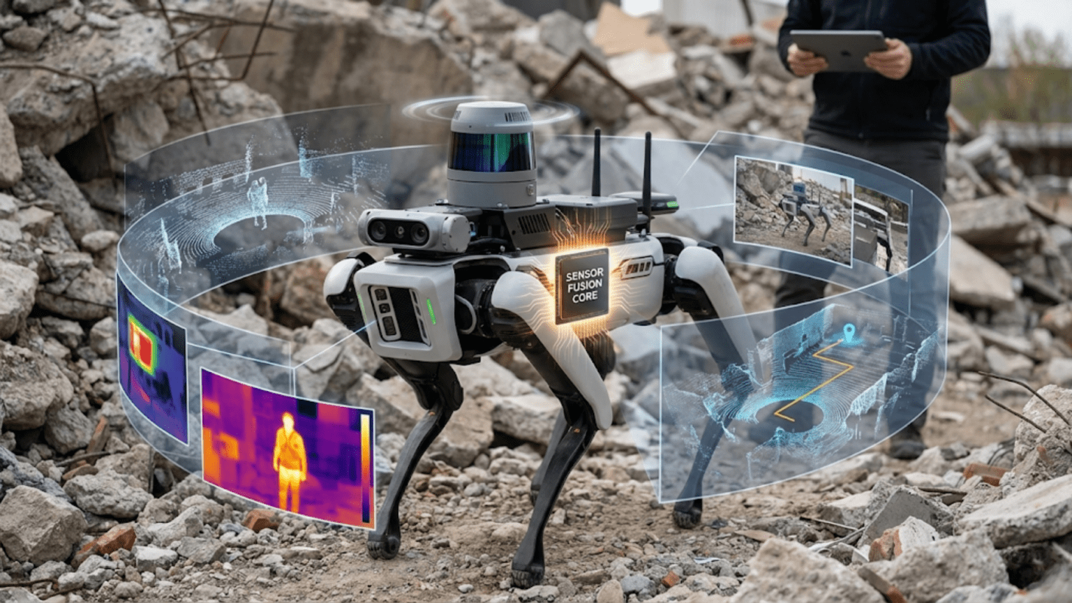
Sensor fusion is the process of combining data from multiple sensors to produce a more accurate, reliable, and complete picture of the environment than any single sensor could provide alone—compensating for individual sensor weaknesses, cross-validating readings to detect faults, and extracting information impossible to obtain from a single measurement source. Robots need multiple sensors because every sensor technology has blind spots, noise characteristics, range limitations, and failure modes that make sole reliance on any one sensor dangerously unreliable for real-world autonomous operation.
Your ultrasonic distance sensor works flawlessly indoors but saturates in bright sunlight. Your infrared line sensor loses the track when the floor transitions from wood to carpet. Your wheel encoders count rotation accurately but accumulate position error over dozens of meters as tiny wheel slips go uncorrected. Your gyroscope measures rotation rate precisely but drifts over time due to bias errors. Your accelerometer measures tilt angle accurately when stationary but becomes useless during rapid motion. Each sensor, examined in isolation, appears functional and reasonably accurate. Each sensor, trusted exclusively in a real-world environment, eventually fails in ways that cause your robot to crash, wander off course, or make dangerously wrong decisions.
This is the fundamental challenge of robotic sensing: the world is complex, environments are variable, and no single sensor perceives everything accurately under all conditions. The solution that roboticists have developed over decades—and that nature arrived at billions of years earlier in biological organisms—is combining multiple sensing modalities to compensate for individual weaknesses and build a more complete, more reliable picture of reality. This approach, called sensor fusion, transforms collections of imperfect sensors into robust perceptual systems that work reliably in conditions where individual sensors would fail.
Understanding sensor fusion is essential for any roboticist moving beyond the simplest projects. The moment your robot needs to navigate reliably across varying surfaces, operate in different lighting conditions, maintain position accuracy over extended distances, or make safety-critical decisions based on sensor data, you need sensor fusion. This article explains why single sensors fail, what sensor fusion accomplishes, how to implement common fusion techniques from simple to sophisticated, and how to design multi-sensor systems that make your robots genuinely robust.
Why Individual Sensors Always Fail Eventually
Before understanding sensor fusion, you need to viscerally understand why single-sensor approaches inevitably break down. Each sensor technology has fundamental limitations that no amount of clever programming can overcome without additional information sources.
The Fundamental Problem: Every Sensor Has Blind Spots
Ultrasonic sensors measure distance accurately for most surfaces but fail completely on soft, angled, or very close targets. They cannot distinguish between a real obstacle and a specular reflection from a smooth surface. Multiple ultrasonic sensors operating simultaneously interfere with each other. Heavy rain or wind disrupts outdoor measurements.
Infrared sensors provide useful proximity and line data but are overwhelmed by ambient infrared (sunlight), confused by certain surface materials that absorb or reflect IR unexpectedly, and limited to short ranges. Black foam absorbs IR like a line—an IR line follower can’t distinguish between the deliberate black track and a black floor tile.
Wheel encoders provide precise rotation counts but cannot detect wheel slip. When a wheel slides instead of rolling, the encoder counts rotations that produced no forward motion—your robot thinks it’s moved 50 cm when it’s actually slid in place. Encoder errors accumulate over time, making position estimates increasingly unreliable.
Gyroscopes measure rotation rate accurately over short periods but suffer from bias drift—a small constant error in the output integrates into growing angular error over time. A gyroscope reporting 0.1 degrees/second of false drift accumulates 6 degrees of heading error per minute and 360 degrees per hour—enough to completely disorient a robot over a long mission.
Accelerometers measure both gravity (useful for tilt detection) and dynamic acceleration (movement). During motion, dynamic acceleration contaminates tilt measurements. A robot accelerating forward sees its accelerometer tip forward even if the robot is perfectly level—the sensor cannot distinguish between tilt and acceleration.
GPS provides absolute position but only outdoors, with high latency (typically 1 Hz update rate), significant noise (±3-5 meters consumer grade), and complete failure in any structure, tunnel, or dense urban canyon where satellite signals can’t reach.
Cameras provide rich visual information but are utterly useless in darkness without illumination, degraded by motion blur, computationally expensive to process, and confused by unusual lighting conditions, reflections, and texture-poor environments.
The Noise Problem: No Sensor Reads Perfectly
Beyond fundamental limitations, every sensor produces noisy measurements—readings that fluctuate around the true value due to:
Thermal noise: Random electron movement in electronic components creates voltage fluctuations that appear as measurement noise. This is irreducible—it exists at the quantum level.
Quantization noise: Digital sensors convert continuous physical quantities to discrete digital values. The gap between adjacent digital levels appears as noise in the measurement.
Environmental noise: Vibrations, electromagnetic interference, temperature variations, and countless other environmental factors perturb measurements unpredictably.
Sampling effects: Sensors that measure discrete samples miss what happens between samples. A robot moving rapidly might collide with an object that appears only between sensor readings.
The combined effect is that every sensor reading represents the true value plus some noise component. Individual readings can be significantly wrong. Decisions based on single noisy readings produce unreliable, erratic robot behavior.
Why This Matters for Autonomous Robots
A human driver compensates for sensor limitations intuitively—if you can’t see well due to rain, you slow down and listen more carefully. Your brain combines visual information, vestibular (balance) sensation, proprioception (body position sense), auditory information, and memory to maintain accurate awareness of your position and the environment.
Autonomous robots need the same multi-modal integration. A robot that relies on one sensor type will exhibit the limitations of that sensor as behavioral failures—driving off edges that aren’t visible to its sensors, losing track of lines when surface properties change, reporting wrong positions when wheel slip occurs. Designing robust robots requires consciously addressing these failure modes through sensor fusion.
The Core Concepts of Sensor Fusion
Sensor fusion encompasses several distinct techniques, ranging from simple averaging to complex probabilistic filtering. Understanding the conceptual framework helps you choose the right approach for each situation.
Concept 1: Redundancy — Cross-Validation and Fault Detection
The simplest form of sensor fusion uses multiple identical or similar sensors to detect when one is malfunctioning. If two sensors agree, their reading is probably correct. If they disagree significantly, at least one is faulty.
float sensor1 = readSensor1();
float sensor2 = readSensor2();

float difference = abs(sensor1 - sensor2);
const float maxExpectedDiff = 5.0;  // Maximum normal difference

if (difference > maxExpectedDiff) {
  // Sensors disagree significantly - possible fault
  Serial.println("WARNING: Sensor disagreement detected!");
  Serial.print("Sensor 1: "); Serial.println(sensor1);
  Serial.print("Sensor 2: "); Serial.println(sensor2);

  // Use conservative estimate or stop for safety
  useSafetyDefault();
} else {
  // Sensors agree - use average
  float fusedValue = (sensor1 + sensor2) / 2.0;
  useValue(fusedValue);
}When to use redundancy:
- Safety-critical measurements where failure is dangerous
- Expensive or long-running missions where sensor failure could be catastrophic
- Any measurement that would cause significant problems if wrong
Limitations:
- Two sensors can both fail in the same way (common-cause failure)
- Requires identical measurement characteristics for meaningful comparison
- Adds cost and weight
Concept 2: Complementarity — Using Different Sensors for Different Conditions
Complementary fusion uses different sensor types that each work well under conditions where the other fails. Combined, they cover each other’s blind spots.
Classic example: Accelerometer + Gyroscope for tilt measurement
- Gyroscope alone: Accurate short-term but drifts over time
- Accelerometer alone: Accurate long-term (gravity provides reference) but noisy during motion
- Combined: Each corrects the other’s weakness—gyroscope handles short-term dynamics, accelerometer corrects long-term drift
Implementation concept:
float tiltFromGyro = integrateGyroscope();      // Accurate fast, drifts slow
float tiltFromAccel = calculateFromAccel();     // Noisy fast, accurate slow

// Trust gyroscope for fast changes, accelerometer for slow drift correction
float fusedTilt = 0.98 * tiltFromGyro + 0.02 * tiltFromAccel;This simple weighting—98% gyroscope, 2% accelerometer—captures the essential complementary fusion idea: trust the fast sensor for dynamic behavior, let the slow sensor correct long-term drift.
Concept 3: Triangulation and Cross-Referencing
Different sensors measuring related quantities can be cross-referenced to improve accuracy or detect inconsistencies.
Example: GPS + Odometry for position
- GPS provides absolute position but noisy and slow-updating
- Odometry provides smooth, fast-updating relative position but accumulates drift
Fuse them: use odometry for smooth moment-to-moment position tracking, periodically correct accumulated drift using GPS absolute readings:
// Pseudocode for GPS + Odometry fusion
void updatePosition() {
  // Update position using odometry (fast, smooth)
  float odometryDeltaX = getOdometryDeltaX();
  float odometryDeltaY = getOdometryDeltaY();

  estimatedX += odometryDeltaX;
  estimatedY += odometryDeltaY;

  // Periodically correct using GPS (absolute, slower)
  if (newGPSDataAvailable()) {
    float gpsX = getGPSX();
    float gpsY = getGPSY();

    // Blend GPS correction with odometry estimate
    // (Kalman filter would do this optimally)
    float alpha = 0.3;  // Trust GPS 30%, odometry 70%
    estimatedX = alpha * gpsX + (1 - alpha) * estimatedX;
    estimatedY = alpha * gpsY + (1 - alpha) * estimatedY;
  }
}Concept 4: Weighted Averaging — Trusting Better Sensors More
When multiple sensors measure the same quantity but with different accuracy levels, weight them by their reliability:
// Three distance sensors with different accuracy levels
float distanceUltrasonic = readUltrasonic();   // Accurate to ±2cm
float distanceIR = readIRSensor();              // Accurate to ±5cm
float distanceLaser = readLaserToF();           // Accurate to ±1mm

// Weights inversely proportional to uncertainty
float weightUltrasonic = 1.0 / 4.0;    // 1/variance = 1/4
float weightIR = 1.0 / 25.0;           // 1/25
float weightLaser = 1.0 / 0.01;        // 1/0.01 = 100 (most trusted)

float totalWeight = weightUltrasonic + weightIR + weightLaser;

float fusedDistance = (distanceUltrasonic * weightUltrasonic +
                       distanceIR * weightIR +
                       distanceLaser * weightLaser) / totalWeight;

// fusedDistance heavily weighted toward laser (most accurate)This inverse-variance weighting is mathematically optimal when sensor errors are independent—the fused result has lower variance than any individual sensor.
Implementing Sensor Fusion: Practical Techniques
Technique 1: Complementary Filter for IMU
The complementary filter is the workhorse of attitude estimation in hobby robotics. It combines gyroscope and accelerometer data to estimate tilt angle with both short-term accuracy and long-term stability:
#include <Wire.h>
#include <MPU6050.h>  // Install via Arduino Library Manager

MPU6050 imu;

// Complementary filter parameter
// Higher alpha = trust gyroscope more (faster response, more drift)
// Lower alpha = trust accelerometer more (more noise, less drift)
const float alpha = 0.98;

float pitch = 0;  // Tilt around left-right axis (degrees)
float roll = 0;   // Tilt around front-back axis (degrees)

unsigned long lastTime = 0;

void setup() {
  Wire.begin();
  Serial.begin(9600);

  imu.initialize();

  if (!imu.testConnection()) {
    Serial.println("MPU6050 connection failed!");
    while(1);
  }

  Serial.println("IMU initialized - complementary filter running");
  lastTime = millis();
}

void loop() {
  // Calculate time step
  unsigned long currentTime = millis();
  float dt = (currentTime - lastTime) / 1000.0;  // seconds
  lastTime = currentTime;

  // Read raw IMU data
  int16_t ax, ay, az;  // Accelerometer raw values
  int16_t gx, gy, gz;  // Gyroscope raw values
  imu.getMotion6(&ax, &ay, &az, &gx, &gy, &gz);

  // Convert gyroscope to degrees/second
  // MPU6050 default: ±250 deg/s range = 131 LSB/deg/s
  float gyroRateX = gx / 131.0;  // deg/s (contributes to roll)
  float gyroRateY = gy / 131.0;  // deg/s (contributes to pitch)

  // Convert accelerometer to g-force
  // MPU6050 default: ±2g range = 16384 LSB/g
  float accelX = ax / 16384.0;
  float accelY = ay / 16384.0;
  float accelZ = az / 16384.0;

  // Calculate tilt from accelerometer (only valid when stationary)
  float accelPitch = atan2(accelY, accelZ) * 180.0 / PI;
  float accelRoll = atan2(-accelX, sqrt(accelY*accelY + accelZ*accelZ))
                    * 180.0 / PI;

  // Complementary filter:
  // Fast changes: trust gyroscope (integrate rate to get angle)
  // Slow drift correction: blend in accelerometer reading
  pitch = alpha * (pitch + gyroRateY * dt) + (1 - alpha) * accelPitch;
  roll = alpha * (roll + gyroRateX * dt) + (1 - alpha) * accelRoll;

  // Output fused attitude estimate
  Serial.print("Pitch: ");
  Serial.print(pitch, 2);
  Serial.print("°, Roll: ");
  Serial.print(roll, 2);
  Serial.println("°");

  delay(10);  // 100 Hz update rate
}Tuning the alpha parameter:
alpha = 0.99: Very responsive to fast motion, allows significant drift (use when motion is dynamic and quick)alpha = 0.98: Good default for most applicationsalpha = 0.95: More accelerometer influence, less drift but noisier (use when motion is gentle and orientation accuracy matters)
Technique 2: Multi-Sensor Obstacle Detection
Combine ultrasonic and infrared sensors for reliable obstacle detection that works where each individual sensor might fail:
// Sensor pins
const int ultrasonicTrig = 9;
const int ultrasonicEcho = 10;
const int irSensorLeft = A0;
const int irSensorRight = A1;

// Thresholds
const float ultrasonicObstacleThreshold = 30.0;  // cm
const int irObstacleThreshold = 400;               // ADC value

// Confidence levels
float obstacleConfidence = 0.0;

struct ObstacleAssessment {
  bool detected;
  float confidence;   // 0.0 = no obstacle, 1.0 = certain obstacle
  float estimatedDistance;
  String detectionSource;
};

ObstacleAssessment assessObstacles() {
  ObstacleAssessment result;
  result.detected = false;
  result.confidence = 0.0;
  result.estimatedDistance = 999.0;
  result.detectionSource = "none";

  // Read ultrasonic sensor
  float ultrasonicDist = measureUltrasonicDistance();
  bool ultrasonicDetects = (ultrasonicDist > 0 &&
                             ultrasonicDist < ultrasonicObstacleThreshold);

  // Read IR sensors
  int irLeft = analogRead(irSensorLeft);
  int irRight = analogRead(irSensorRight);
  bool irLeftDetects = (irLeft > irObstacleThreshold);
  bool irRightDetects = (irRight > irObstacleThreshold);
  bool irDetects = irLeftDetects || irRightDetects;

  // Sensor fusion logic
  if (ultrasonicDetects && irDetects) {
    // Both sensor types agree - HIGH confidence
    result.detected = true;
    result.confidence = 0.95;
    result.estimatedDistance = ultrasonicDist;  // Ultrasonic more precise
    result.detectionSource = "ultrasonic+IR (confirmed)";

  } else if (ultrasonicDetects && !irDetects) {
    // Only ultrasonic detects - MEDIUM confidence
    // Could be soft/angled object that absorbs IR
    // or IR range limitation
    result.detected = true;
    result.confidence = 0.65;
    result.estimatedDistance = ultrasonicDist;
    result.detectionSource = "ultrasonic only";

  } else if (!ultrasonicDetects && irDetects) {
    // Only IR detects - MEDIUM confidence
    // Could be very close object (ultrasonic dead zone)
    // or IR false positive from ambient light
    result.detected = true;
    result.confidence = 0.60;
    result.estimatedDistance = 10.0;  // Estimate close range
    result.detectionSource = "IR only";

  } else {
    // Neither detects - confident NO obstacle in range
    result.detected = false;
    result.confidence = 0.05;  // Small residual uncertainty
    result.detectionSource = "clear";
  }

  return result;
}

void loop() {
  ObstacleAssessment obstacle = assessObstacles();

  Serial.print("Obstacle: ");
  Serial.print(obstacle.detected ? "YES" : "NO");
  Serial.print(", Confidence: ");
  Serial.print(obstacle.confidence * 100);
  Serial.print("%, Distance: ");
  Serial.print(obstacle.estimatedDistance);
  Serial.print(" cm, Source: ");
  Serial.println(obstacle.detectionSource);

  // Action based on confidence level
  if (obstacle.confidence > 0.8) {
    // High confidence - definitely stop
    stopMotors();
    Serial.println("ACTION: STOP (high confidence obstacle)");
  } else if (obstacle.confidence > 0.5) {
    // Medium confidence - slow down and verify
    slowMotors();
    Serial.println("ACTION: SLOW (uncertain obstacle)");
  } else {
    // Low/no obstacle confidence - proceed
    fullSpeed();
    Serial.println("ACTION: PROCEED");
  }

  delay(100);
}

float measureUltrasonicDistance() {
  digitalWrite(ultrasonicTrig, LOW);
  delayMicroseconds(2);
  digitalWrite(ultrasonicTrig, HIGH);
  delayMicroseconds(10);
  digitalWrite(ultrasonicTrig, LOW);

  long duration = pulseIn(ultrasonicEcho, HIGH, 25000);
  if (duration == 0) return -1;
  return duration / 58.0;
}

void stopMotors() { /* implementation */ }
void slowMotors() { /* implementation */ }
void fullSpeed() { /* implementation */ }Technique 3: Encoder + IMU Odometry Fusion
Combine wheel encoders and IMU heading for more accurate position tracking:
// Robot physical parameters
const float wheelDiameter = 6.5;   // cm
const float wheelBase = 15.0;      // cm
const float wheelCircumference = PI * wheelDiameter;
const int pulsesPerRevolution = 740;
const float distPerPulse = wheelCircumference / pulsesPerRevolution;

// Position state
float robotX = 0;
float robotY = 0;
float headingEncoder = 0;    // Heading from encoder differential
float headingGyro = 0;       // Heading from gyroscope
float headingFused = 0;      // Fused heading estimate

// Weights for heading fusion
const float encoderWeight = 0.7;  // Encoders good for short-term
const float gyroWeight = 0.3;     // Gyro corrects encoder slip

volatile long leftPulses = 0;
volatile long rightPulses = 0;
long lastLeftPulses = 0, lastRightPulses = 0;
unsigned long lastUpdateTime = 0;

// Gyro variables
float gyroBiasZ = 0;  // Calibrated gyro bias

void calibrateGyroBias() {
  Serial.println("Calibrating gyro - keep robot still for 3 seconds...");
  float sum = 0;
  int samples = 0;
  unsigned long start = millis();

  while (millis() - start < 3000) {
    int16_t gz;
    // Read gyro Z axis (yaw rate)
    // (Actual reading depends on your IMU library)
    sum += readGyroZ();
    samples++;
    delay(10);
  }

  gyroBiasZ = sum / samples;
  Serial.print("Gyro bias: ");
  Serial.println(gyroBiasZ);
}

void updateFusedOdometry() {
  unsigned long currentTime = millis();
  float dt = (currentTime - lastUpdateTime) / 1000.0;
  lastUpdateTime = currentTime;

  // Read encoder pulses
  long lc, rc;
  noInterrupts();
  lc = leftPulses;
  rc = rightPulses;
  interrupts();

  long leftDelta = lc - lastLeftPulses;
  long rightDelta = rc - lastRightPulses;
  lastLeftPulses = lc;
  lastRightPulses = rc;

  // Calculate distances
  float leftDist = leftDelta * distPerPulse;
  float rightDist = rightDelta * distPerPulse;
  float centerDist = (leftDist + rightDist) / 2.0;

  // Encoder-based heading change
  float deltaHeadingEncoder = (rightDist - leftDist) / wheelBase;

  // Gyro-based heading change (integrate angular rate)
  float gyroRate = readGyroZ() - gyroBiasZ;  // Remove bias
  float deltaHeadingGyro = gyroRate * dt * PI / 180.0;  // Convert to radians

  // Fuse heading estimates
  float deltaHeadingFused = encoderWeight * deltaHeadingEncoder +
                             gyroWeight * deltaHeadingGyro;

  headingFused += deltaHeadingFused;

  // Keep heading in -PI to PI range
  while (headingFused > PI) headingFused -= 2 * PI;
  while (headingFused < -PI) headingFused += 2 * PI;

  // Update position using fused heading
  float midHeading = headingFused - deltaHeadingFused / 2.0;
  robotX += centerDist * cos(midHeading);
  robotY += centerDist * sin(midHeading);

  // Debug output
  Serial.print("X: "); Serial.print(robotX, 1);
  Serial.print(" Y: "); Serial.print(robotY, 1);
  Serial.print(" Heading: ");
  Serial.print(headingFused * 180.0 / PI, 1);
  Serial.println(" deg");
}

float readGyroZ() {
  // Implementation depends on your IMU library
  return 0;  // Placeholder
}Technique 4: Voting-Based Sensor Fusion
For binary decisions (obstacle/no obstacle, on line/off line), use majority voting from multiple sensors:
const int numSensors = 5;
const int sensorPins[numSensors] = {A0, A1, A2, A3, A4};
const int lineThreshold = 500;

// Voting result structure
struct VoteResult {
  int votesForLine;       // Number of sensors detecting line
  int votesAgainstLine;   // Number of sensors not detecting line
  float confidence;       // 0.0 to 1.0
  bool lineDetected;
};

VoteResult voteOnLineDetection() {
  VoteResult result;
  result.votesForLine = 0;
  result.votesAgainstLine = 0;

  for (int i = 0; i < numSensors; i++) {
    int reading = analogRead(sensorPins[i]);
    if (reading > lineThreshold) {
      result.votesForLine++;
    } else {
      result.votesAgainstLine++;
    }
  }

  // Calculate confidence based on vote margin
  int margin = abs(result.votesForLine - result.votesAgainstLine);
  result.confidence = (float)margin / numSensors;

  // Decision by majority
  result.lineDetected = (result.votesForLine > result.votesAgainstLine);

  return result;
}

void loop() {
  VoteResult vote = voteOnLineDetection();

  Serial.print("Votes FOR line: ");
  Serial.print(vote.votesForLine);
  Serial.print(", AGAINST: ");
  Serial.print(vote.votesAgainstLine);
  Serial.print(", Confidence: ");
  Serial.print(vote.confidence * 100);
  Serial.print("%, Decision: ");
  Serial.println(vote.lineDetected ? "LINE DETECTED" : "NO LINE");

  // Act on decision
  if (vote.lineDetected && vote.confidence > 0.6) {
    // High confidence detection
    followLine();
  } else if (vote.lineDetected && vote.confidence <= 0.6) {
    // Low confidence - proceed cautiously
    slowFollowLine();
  } else {
    // No line detected
    searchForLine();
  }

  delay(20);
}Real-World Sensor Fusion Examples in Commercial Robots
Understanding how professional systems implement sensor fusion contextualizes the techniques and inspires more sophisticated implementations.
Self-Driving Vehicles
Modern autonomous vehicles use sensor fusion as a core architectural principle, combining:
- LIDAR: 3D point cloud of surroundings (precise geometry, works day/night)
- Cameras: Visual appearance, color, traffic signs, lane markings (rich but lighting-dependent)
- RADAR: Object detection and velocity at long range (works in fog and rain)
- GPS/GNSS: Absolute position (outdoor, moderate accuracy)
- High-resolution maps: Pre-mapped environment for reference
- IMU: Short-term motion tracking between sensor updates
No single technology would suffice. LIDAR misses thin objects and struggles with retro-reflective surfaces. Cameras fail in darkness and glare. RADAR can’t resolve fine detail. GPS fails indoors and near buildings. Each sensor’s failures are covered by others’ strengths.
Drone Flight Controllers
Quadcopters use complementary filtering and extended Kalman filtering combining:
- Gyroscope: Fast rotation rate for immediate attitude corrections
- Accelerometer: Long-term attitude reference and linear acceleration
- Magnetometer (compass): Absolute heading reference (corrects gyro yaw drift)
- Barometer: Altitude above sea level
- GPS: Horizontal position for position hold and navigation
- Optical flow camera: Precise horizontal position hold over textured ground (GPS-denied)
The flight controller runs sensor fusion algorithms at 1000 Hz to maintain stable flight—demonstrating how critical fast, accurate fusion is for dynamic systems.
Robot Vacuum Cleaners
Consumer robot vacuums demonstrate sophisticated sensor fusion in an affordable product:
- Cliff sensors (IR): Detect stairs and drop-offs
- Bump sensors: Physical contact detection
- Wall sensors (IR): Side distance for wall following
- Wheel encoders: Dead reckoning navigation
- Camera/LIDAR (premium models): Room mapping and localization
- Dirt detection (acoustic): Sense when more cleaning is needed
The robot builds and maintains a map by fusing encoder odometry with camera or LIDAR data, enabling systematic coverage rather than random wandering.
Designing a Multi-Sensor System: Practical Guidelines
Effective sensor fusion requires thoughtful system design, not just combining every available sensor.
Guideline 1: Identify Failure Modes First
Before adding sensors, explicitly list how your robot could fail:
Robot: Line-following robot
Failure modes:
1. Line disappears at intersection (IR sensors confused)
2. Ambient light changes cause threshold drift
3. Robot drifts off straight sections between turns
4. Cross-lines in track pattern confuse navigation

Sensor additions to address each:
1. Add IMU to maintain heading through intersections
2. Add ambient light sensor for adaptive thresholding
3. Add encoders for straight-line distance tracking
4. Add camera for intersection pattern recognitionThis systematic analysis ensures sensor additions address real failure modes rather than adding complexity without benefit.
Guideline 2: Match Sensor Characteristics to Fusion Requirements
For complementary filtering to work, sensors must have complementary error characteristics:
Good complementary pairs:
- Gyroscope (fast, drifts) + Accelerometer (slow, stable long-term)
- Encoder (relative, accumulated error) + GPS (absolute, noisy)
- Short-range IR (precise, limited range) + Long-range ultrasonic (approximate, wide range)
Poor complementary pairs:
- Two identical sensors (same failure modes, same noise characteristics)
- Sensors with the same environmental dependencies (two sensors that both fail in rain)
Guideline 3: Start Simple, Add Complexity Only When Needed
Resist the urge to implement complex algorithms immediately:
- Start with simple weighted averaging or threshold-based fusion
- Test thoroughly in your specific environment
- Identify remaining failure modes through testing
- Add complexity only where simple approaches prove insufficient
A simple complementary filter often outperforms a poorly tuned Kalman filter. Match algorithm complexity to your problem’s needs and your ability to tune correctly.
Guideline 4: Calibrate and Validate
Each sensor needs calibration before fusion:
void runSystemCalibration() {
  Serial.println("=== System Calibration ===");

  // Calibrate gyro bias (keep robot still)
  Serial.println("1. Calibrating gyroscope...");
  calibrateGyro();

  // Calibrate IR sensors (expose to black and white)
  Serial.println("2. Calibrating IR sensors...");
  calibrateIRSensors();

  // Calibrate encoder counts per revolution
  Serial.println("3. Calibrating wheel encoders...");
  calibrateEncoders();

  // Validate fusion
  Serial.println("4. Validating sensor fusion...");
  validateFusion();

  Serial.println("Calibration complete!");
}

void validateFusion() {
  // Drive known distance, verify odometry accuracy
  Serial.println("Drive 50cm forward for validation...");
  driveDistance(50.0, 150);

  long lc, rc;
  noInterrupts();
  lc = leftPulses;
  rc = rightPulses;
  interrupts();

  float leftActual = lc * distPerPulse;
  float rightActual = rc * distPerPulse;

  Serial.print("Expected: 50cm, Left actual: ");
  Serial.print(leftActual);
  Serial.print("cm, Right actual: ");
  Serial.println(rightActual);
}Comparison Table: Sensor Fusion Techniques
| Technique | Complexity | Best For | Computational Cost | Tuning Required | Typical Application |
|---|---|---|---|---|---|
| Simple Averaging | Very Low | Identical redundant sensors | Minimal | None | Multi-sensor distance averaging |
| Weighted Average | Low | Different-accuracy sensors | Minimal | Weight selection | Multi-IMU, multi-distance |
| Complementary Filter | Low-Medium | Fast + slow sensor pairs | Low | Alpha parameter | Gyro + accelerometer attitude |
| Voting / Majority | Low | Binary decisions, fault detection | Minimal | Threshold | Line detection, obstacle detection |
| Kalman Filter | High | Linear systems, Gaussian noise | Medium | Process/measurement noise matrices | Position tracking, IMU fusion |
| Extended Kalman Filter | Very High | Nonlinear systems | High | Jacobians + noise matrices | SLAM, full vehicle state estimation |
| Particle Filter | Very High | Non-Gaussian distributions | Very High | Particle count, motion model | Robot localization in maps |
Common Sensor Fusion Mistakes
Mistake 1: Trusting All Sensors Equally
Not all sensors deserve equal trust in all conditions:
// Wrong: Equal weighting regardless of conditions
float fused = (sensor1 + sensor2) / 2.0;

// Right: Dynamic weighting based on current conditions
float weight1 = assessSensor1Reliability();
float weight2 = assessSensor2Reliability();
float fused = (sensor1 * weight1 + sensor2 * weight2) / (weight1 + weight2);

float assessSensor1Reliability() {
  // Lower reliability in bright light (IR sensor)
  int ambientLight = analogRead(lightSensorPin);
  if (ambientLight > 800) return 0.3;  // Low trust in bright light
  return 1.0;  // Normal trust
}Mistake 2: Ignoring Sensor Timing
Sensors don’t all update at the same rate. Using old data as if it were current introduces errors:
// Track when each sensor was last updated
unsigned long lastUltrasonicUpdate = 0;
unsigned long lastIMUUpdate = 0;
const unsigned long maxDataAge = 200;  // Data older than 200ms considered stale

bool isSensorDataFresh(unsigned long lastUpdate) {
  return (millis() - lastUpdate) < maxDataAge;
}

void updateFusedReading() {
  if (!isSensorDataFresh(lastUltrasonicUpdate)) {
    // Ultrasonic data is stale - don't use it
    Serial.println("Warning: Ultrasonic data stale");
    useDefaultUltrasonicBehavior();
    return;
  }
  // Proceed with fresh data
}Mistake 3: Not Handling Sensor Failures Gracefully
Design systems that degrade gracefully when sensors fail:
// Check sensor health before fusion
bool checkAllSensors() {
  bool healthy = true;

  float ultrasonicReading = measureUltrasonicDistance();
  if (ultrasonicReading < 0) {
    Serial.println("WARNING: Ultrasonic sensor failed");
    ultrasonicActive = false;
    healthy = false;
  }

  int imuStatus = checkIMUConnection();
  if (imuStatus != 0) {
    Serial.println("WARNING: IMU connection lost");
    imuActive = false;
    healthy = false;
  }

  return healthy;
}

float getFusedDistance() {
  if (ultrasonicActive && imuActive) {
    return fullFusionDistance();    // Both sensors working
  } else if (ultrasonicActive) {
    return ultrasonicOnlyDistance(); // Degraded mode
  } else if (imuActive) {
    return imuEstimatedDistance();  // Further degraded
  } else {
    stopForSafety();  // No sensors - must stop
    return -1;
  }
}Conclusion: Sensor Fusion as Robotic Wisdom
Individual sensors provide data. Sensor fusion provides understanding. The difference is profound. A robot reading a single distance sensor knows “this number from this instrument.” A robot with sensor fusion knows “an obstacle is approximately here, with this confidence, detectable by these modalities, likely of this type, and I have this level of certainty in my overall environmental model.” That richer, validated understanding supports better decisions, more graceful handling of uncertainty, and far more robust real-world performance.
The progression in sensor fusion sophistication mirrors the progression in robotics capability. Simple robots with single sensors work in controlled environments where conditions match the sensor’s ideal operating range. More capable robots operating in diverse, unpredictable environments need the cross-validation, complementarity, and graceful degradation that sensor fusion provides. The most capable autonomous systems—self-driving vehicles, space exploration robots, surgical robots—invest heavily in sophisticated fusion architectures precisely because reliable performance in uncertain environments demands it.
You don’t need to implement a full Extended Kalman Filter to benefit from sensor fusion. Start with the simplest techniques: average two redundant sensors, combine a fast sensor with a slow drift-correcting sensor using a complementary filter, make decisions by majority vote from multiple binary sensors. These simple approaches already provide meaningful reliability improvements over single-sensor designs.
As your experience grows, implement more sophisticated techniques where your specific application demands them. Learn where your robot’s single-sensor behavior fails, then design fusion approaches that address those specific failure modes. Tune carefully, validate empirically, and resist premature complexity—a well-tuned simple filter often beats a poorly tuned sophisticated one.
Every great autonomous robot—from your first wheeled platform to the exploration robots on other worlds—uses sensor fusion to transform imperfect individual perceptions into a reliable understanding of reality. Master sensor fusion, and you unlock the essential capability that separates robots that work in demonstrations from robots that work in the real world.