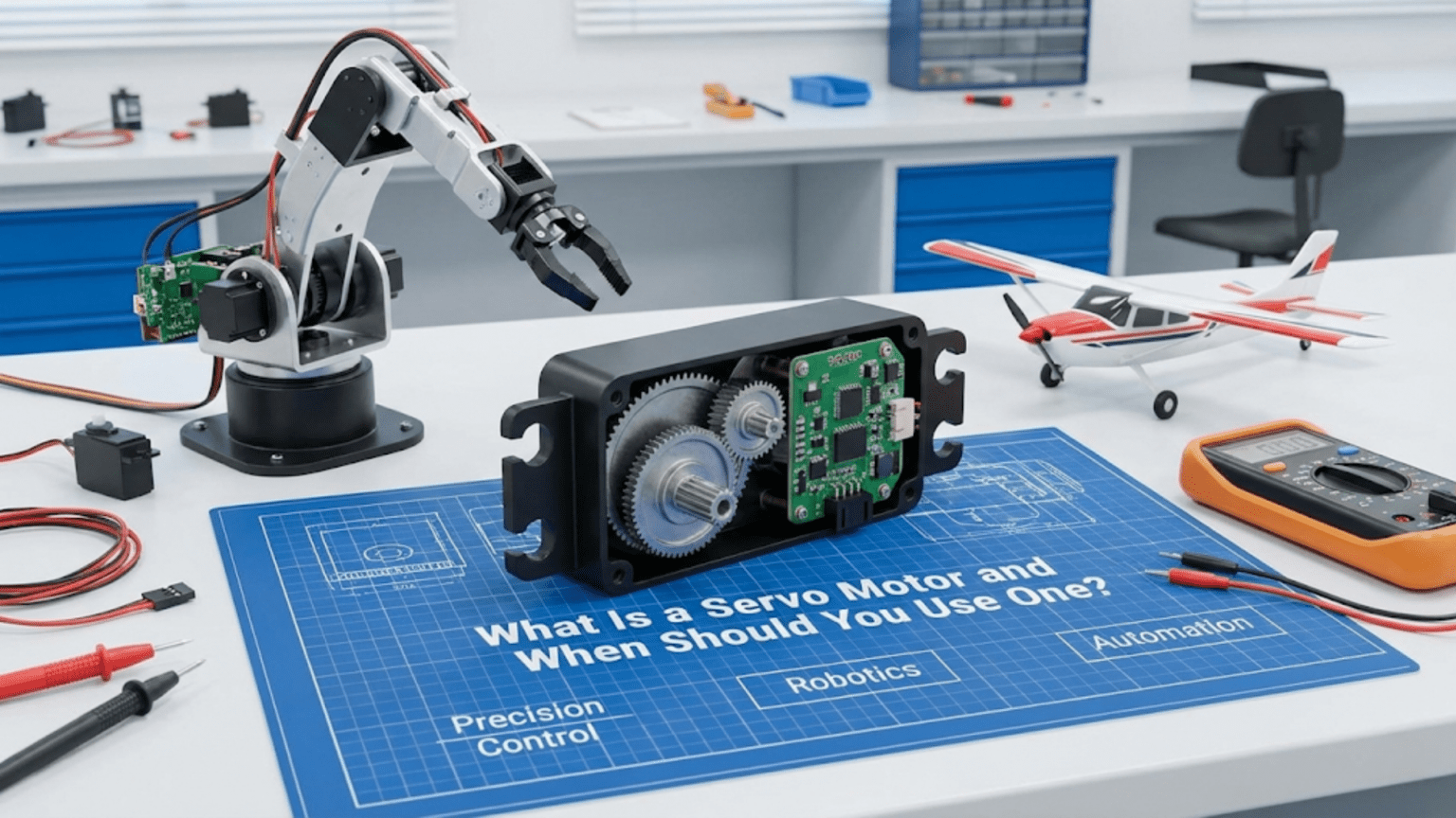
A servo motor is a self-contained actuator combining a DC motor, a gearbox for torque multiplication, a position sensor (typically a potentiometer), and control electronics into a single package that can move to and hold a precise angular position commanded by a PWM signal—making servos the ideal choice whenever your robot needs controlled rotational positioning rather than continuous spinning, such as steering a car robot’s front wheels, tilting a sensor platform, operating a gripper, or moving the joints of a robotic arm.
You’re building a robot arm and need the elbow joint to move to exactly 45 degrees and hold that position firmly while supporting a load. You’re designing a camera pan-tilt mount that needs smooth, precise movement between specific angles. You’re steering a wheeled robot and need the front wheels to turn to a precise angle and stay there while the robot drives. In all of these situations, a plain DC motor falls drastically short—it spins continuously, has no position feedback, and requires external encoders, gearboxes, and control circuitry to do what you actually need. A servo motor provides all of that in a single, inexpensive, easy-to-use package.
Servo motors represent one of the most beginner-friendly yet genuinely powerful actuator choices in robotics. A standard hobby servo connects with three wires, responds to a single PWM signal from any digital pin, moves to commanded angles with no additional circuitry, and holds position against moderate loads without any feedback code on your part. The internal closed-loop control handles everything—you simply say “go to 90 degrees” and the servo goes there, corrects disturbances, and stays until you command otherwise.
This article provides a complete guide to servo motors in robotics: the internal mechanism that makes position control possible, the PWM signal protocol that commands them, every significant servo type and when each applies, how to wire and program servos for common robotics applications, the practical limits and failure modes to design around, and a clear decision framework for when servo motors are the right choice versus alternatives. Whether you’re choosing your first servo or designing a multi-joint manipulator, this understanding enables informed, confident actuator selection.
Inside a Servo Motor: How Position Control Works
Unlike a plain DC motor that simply spins when powered, a servo motor achieves position control through an internal closed-loop feedback system.
The Four Components Inside Every Servo
1. DC Motor A small, typically high-speed DC motor provides the mechanical power. Left to spin freely, this motor would rotate at thousands of RPM—far too fast for direct use in positioning applications. It provides the force; the other components shape that force into useful work.
2. Gearbox (Gear Train) A multi-stage gear reduction transforms the motor’s high speed and low torque into low speed and high torque. Typical reduction ratios range from 100:1 to 1000:1—a motor spinning at 10,000 RPM with a 200:1 gearbox produces an output shaft rotating at 50 RPM with 200× the torque. The gearbox material (plastic, metal, or hybrid) significantly affects durability and load capacity.
3. Position Sensor (Potentiometer) A rotary potentiometer connects directly to the output shaft. As the shaft rotates, the potentiometer’s resistance changes proportionally, providing a voltage signal representing current shaft position. This position feedback is the key element that enables closed-loop control—without it, the servo would have no way to know where its shaft currently is.
4. Control Electronics (PWM Decoder + Error Amplifier) The control board reads the incoming PWM command signal to determine the desired position, reads the potentiometer to determine actual position, calculates the error (difference between desired and actual), and drives the DC motor to reduce that error. When the shaft reaches the commanded position, the error reaches zero and the motor stops. If an external force disturbs the position, the error reappears and the motor corrects—this is the closed-loop behavior that makes servos hold position actively rather than passively.
The Control Loop in Detail
The servo’s internal control loop runs continuously:
- Read command: Decode the PWM pulse width to determine desired angle
- Read position: Sample potentiometer voltage, convert to current angle
- Calculate error: Error = Desired angle – Current angle
- Drive motor: Apply motor voltage proportional to error magnitude and sign
- Check again: Repeat hundreds of times per second
When the shaft reaches the commanded angle, error = 0, motor voltage = 0, shaft stops. An external force pushing the shaft away creates error, which the motor immediately fights—this is why servos hold position actively.
Dead band: To prevent constant jitter from noise, servos include a dead band—a small error range (typically ±1-2 degrees) where the motor doesn’t activate. This prevents the servo from hunting continuously around the target position.
Why Servos Are “Dumb” at the Interface
Despite their sophisticated internal control, the servo interface is remarkably simple—just a PWM signal encoding desired position. This is intentional: all the complexity is hidden inside the servo, keeping the interface easy. The trade-off is that you can only command position, not directly control speed, torque, or acceleration. More sophisticated digital servos add communication protocols (UART, TTL) for additional control, but standard hobby servos accept only the basic PWM command.
The Servo PWM Protocol
Servo motors use a specific PWM protocol different from the general PWM used for DC motor speed control.
PWM Timing Specifications
Standard servo protocol:
- Signal frequency: 50 Hz (one pulse every 20ms)
- Pulse width range: 1000µs to 2000µs (1ms to 2ms)
- Center position: 1500µs (1.5ms)
- Angular range: Typically 180 degrees total travel
- Voltage: 3.3V or 5V signal level (check your servo)
The pulse width encodes position:
Pulse Width → Position
1000µs (1.0ms) → 0° (full counterclockwise)
1500µs (1.5ms) → 90° (center)
2000µs (2.0ms) → 180° (full clockwise)Extended range: Some servos support 500µs-2500µs, providing up to 270° of travel. Check your servo’s datasheet for actual limits—commanding beyond mechanical limits damages the gearbox.
Why 50 Hz?
The 50 Hz update rate (20ms between pulses) matches the historical origin of servo control in radio-controlled models, where radio transmitters updated at 50 Hz. Modern digital servos can accept update rates up to 333 Hz for more responsive control, but standard analog servos expect 50 Hz. Running analog servos at higher rates can cause overheating of control electronics.
The Servo Library Makes It Simple
Arduino’s built-in Servo library handles all PWM timing details:
#include <Servo.h>

Servo myServo;

void setup() {
  myServo.attach(9);  // Attach to pin 9
  Serial.begin(9600);
}

void loop() {
  // Move to specific angles
  myServo.write(0);    // Full counterclockwise
  delay(1000);

  myServo.write(90);   // Center position
  delay(1000);

  myServo.write(180);  // Full clockwise
  delay(1000);
}Advanced Servo library functions:
// writeMicroseconds() for precise pulse width control
myServo.writeMicroseconds(1500);  // Center (same as write(90))
myServo.writeMicroseconds(1000);  // 0 degrees
myServo.writeMicroseconds(2000);  // 180 degrees

// read() returns last commanded angle
int currentAngle = myServo.read();

// attached() checks if servo is properly attached
if (myServo.attached()) {
  Serial.println("Servo connected");
}

// detach() releases the pin, stops sending pulses
myServo.detach(); // Servo holds last position passivelyWiring Servos to Arduino
Standard servo connectors use three wires with consistent (but not universal) color coding:
Wire Color    Function          Connect To
Brown/Black   Ground (GND)   →  Arduino GND
Red           Power (VCC)    →  5V (external supply for multiple servos)
Orange/Yellow Signal → Any digital pin (PWM not required!)Power supply critical note: The Arduino’s 5V pin can power one small servo during testing but struggles with multiple servos or under load. Servos draw significant current—a standard servo at stall can draw 1-2 amps. For reliable operation:
Small servo, light load, single servo:    Arduino 5V pin (testing only)
Multiple servos or any significant load:  External 5V supply
(share GND with Arduino)Wiring multiple servos:
External 5V supply (+) ──┬── Servo 1 red wire
                         ├── Servo 2 red wire
                         └── Servo 3 red wire

External 5V supply (-) ──┬── Servo 1 brown wire
                         ├── Servo 2 brown wire
                         ├── Servo 3 brown wire
                         └── Arduino GND  (MUST connect grounds)

Servo 1 signal ──────────── Arduino pin 9
Servo 2 signal ──────────── Arduino pin 10
Servo 3 signal ──────────── Arduino pin 11Types of Servo Motors and Their Applications
Servo motors come in several distinct types, each suited to different robotics applications.
Standard Position Servo (0°-180°)
The most common type. The servo moves to commanded angles within its mechanical range and holds there. The potentiometer physically limits rotation to roughly 180 degrees.
Specifications typical of standard servos:
- Travel: ~180 degrees
- Torque: 1-3 kg·cm (small) to 10-25 kg·cm (large)
- Speed: 0.1-0.2 sec/60° (time to move 60 degrees)
- Voltage: 4.8-6V
- Current: 200-500mA running, 500-2000mA stall
Best applications:
- Robot arm joints
- Gripper open/close
- Steering mechanisms
- Pan-tilt camera mounts
- Rudder and elevator control
- Anything needing precise angle positioning
Common examples: SG90 (micro, plastic gears), MG996R (standard, metal gears), HS-755HB (large, high torque)
Continuous Rotation Servo
Modified (or purpose-built) servos where the potentiometer feedback is disconnected or bypassed, allowing continuous 360° rotation. The PWM command now controls speed and direction rather than position:
- 1500µs: Stop
- <1500µs: Rotate one direction (speed proportional to pulse distance from center)
- >1500µs: Rotate other direction
Why use continuous rotation servos instead of DC motors?
- Three-wire interface identical to standard servos (simple code)
- Built-in gearbox provides torque multiplication
- Works with the same Servo library
- No H-bridge needed for direction control
- Convenient for robots using servo-based chassis kits
Limitations versus DC motors:
- No position feedback (unlike position servos)
- Lower top speed than equivalent DC motor
- Less efficient than DC motor + driver solution
- “Neutral” point (stop) varies between units—needs calibration
Code for continuous rotation servo:
#include <Servo.h>

Servo wheelServo;

void setup() {
  wheelServo.attach(9);

  // Calibrate neutral (servo-specific, ~1500µs)
  wheelServo.writeMicroseconds(1500);
  delay(2000);  // Allow calibration
}

void loop() {
  // Forward at full speed
  wheelServo.writeMicroseconds(2000);
  delay(2000);

  // Stop
  wheelServo.writeMicroseconds(1500);
  delay(1000);

  // Reverse at half speed
  wheelServo.writeMicroseconds(1250);  // Halfway between stop and full reverse
  delay(2000);

  // Stop
  wheelServo.writeMicroseconds(1500);
  delay(1000);
}Finding your servo’s true neutral:
// Calibration sketch: find the exact stop point
#include <Servo.h>
Servo contServo;
int pulseWidth = 1500;

void setup() {
  contServo.attach(9);
  Serial.begin(9600);
  Serial.println("Enter pulse width (1000-2000) to test:");
}

void loop() {
  if (Serial.available()) {
    pulseWidth = Serial.parseInt();
    pulseWidth = constrain(pulseWidth, 1000, 2000);
    contServo.writeMicroseconds(pulseWidth);
    Serial.print("Testing: ");
    Serial.println(pulseWidth);
  }
}
// Increase/decrease until servo just barely stops - that's your neutralDigital Servo
Functionally identical to analog servos in external behavior (same PWM protocol, same connector) but with microprocessor-based internal control running at much higher update rates (300-400 Hz vs. 50 Hz internally).
Advantages over analog:
- Faster response to position changes
- More consistent holding torque (updates more frequently)
- Better accuracy and repeatability
- Programmable parameters (via special programmer)
- Less jitter at held positions
Disadvantages:
- More expensive (2-4× cost)
- Slightly higher power consumption
- Overkill for many applications
When digital servos are worth it:
- High-speed mechanisms (fast-moving robotic hands)
- Competition robots where every millisecond matters
- Applications requiring very precise position holding under variable load
- Quadruped walking robots with fast gait cycles
High-Torque / Giant Scale Servo
Physically larger servos with substantially more torque capacity for heavy-load applications:
- Torque: 15-60+ kg·cm
- Weight: 100-400g
- Voltage: 6-8.4V (higher voltage needed)
- Applications: Large robot arms, heavy grippers, vehicle steering
Key consideration: Higher voltage requirements (6V-8.4V) mean you need regulated power supplies at appropriate voltages—Arduino’s 5V pin definitely won’t work.
Micro and Sub-Micro Servo
Tiny servos for weight- and space-constrained applications:
- Weight: 3-15g (SG90: 9g)
- Torque: 0.5-2 kg·cm
- Voltage: 3.3-6V (some work at 3.3V, useful for 3.3V microcontrollers)
- Applications: Small grippers, compact pan-tilt mounts, small robot fingers
The SG90 micro servo is among the most widely used components in hobby robotics—inexpensive (~$2-4), light, and sufficient for many small robot applications.
Practical Servo Applications with Complete Code
Application 1: Smooth Servo Sweeping
Avoid abrupt jumps between positions; move smoothly to reduce mechanical stress:
#include <Servo.h>

Servo myServo;

void setup() {
  myServo.attach(9);
  myServo.write(90);  // Start at center
  delay(500);
}

void loop() {
  sweepTo(0, 2);    // Move to 0° at 2°/step speed
  delay(500);
  sweepTo(180, 2);  // Move to 180°
  delay(500);
  sweepTo(90, 3);   // Return to center faster
  delay(1000);
}

// Move servo smoothly to target angle
// stepDelay: milliseconds between each degree of movement
void sweepTo(int targetAngle, int stepDelay) {
  int currentAngle = myServo.read();

  if (currentAngle < targetAngle) {
    for (int angle = currentAngle; angle <= targetAngle; angle++) {
      myServo.write(angle);
      delay(stepDelay);
    }
  } else {
    for (int angle = currentAngle; angle >= targetAngle; angle--) {
      myServo.write(angle);
      delay(stepDelay);
    }
  }
}Application 2: Sensor Pan-Tilt Mount
A two-servo pan-tilt platform rotates a sensor or camera in two axes:
#include <Servo.h>

Servo panServo;   // Left-right rotation
Servo tiltServo;  // Up-down rotation

// Joystick or potentiometer pins for manual control
const int panPotPin = A0;
const int tiltPotPin = A1;

// Angle limits
const int PAN_MIN = 0, PAN_MAX = 180;
const int TILT_MIN = 30, TILT_MAX = 150;  // Limited to avoid cable strain

// Smoothing
int panAngle = 90, tiltAngle = 90;  // Start at center
const float smoothFactor = 0.1;     // 0=no movement, 1=instant snap

void setup() {
  panServo.attach(9);
  tiltServo.attach(10);

  // Move to center
  panServo.write(90);
  tiltServo.write(90);
  delay(500);

  Serial.begin(9600);
}

void loop() {
  // Read joystick/potentiometer inputs
  int panInput = analogRead(panPotPin);
  int tiltInput = analogRead(tiltPotPin);

  // Map to angle ranges
  int panTarget = map(panInput, 0, 1023, PAN_MIN, PAN_MAX);
  int tiltTarget = map(tiltInput, 0, 1023, TILT_MIN, TILT_MAX);

  // Smooth the movement (exponential moving average)
  panAngle = panAngle + smoothFactor * (panTarget - panAngle);
  tiltAngle = tiltAngle + smoothFactor * (tiltTarget - tiltAngle);

  // Apply to servos
  panServo.write(panAngle);
  tiltServo.write(tiltAngle);

  Serial.print("Pan: "); Serial.print(panAngle);
  Serial.print("°, Tilt: "); Serial.print(tiltAngle);
  Serial.println("°");

  delay(20);  // 50 Hz update rate
}Application 3: Servo-Controlled Gripper
Open and close a gripper based on sensor input:
#include <Servo.h>

Servo gripperServo;

// Gripper positions
const int GRIPPER_OPEN = 160;    // Degrees for fully open
const int GRIPPER_CLOSED = 60;   // Degrees for fully closed
const int GRIPPER_HOLD = 90;     // Partial close for holding

// Contact sensor
const int contactSensorPin = 2;

// State machine
enum GripperState { OPEN, CLOSING, HOLDING, OPENING };
GripperState state = OPEN;

int currentAngle = GRIPPER_OPEN;

void setup() {
  gripperServo.attach(9);
  gripperServo.write(GRIPPER_OPEN);
  pinMode(contactSensorPin, INPUT_PULLUP);
  Serial.begin(9600);
  Serial.println("Gripper ready");
}

void loop() {
  bool objectContact = (digitalRead(contactSensorPin) == LOW);

  switch (state) {
    case OPEN:
      gripperServo.write(GRIPPER_OPEN);
      Serial.println("State: OPEN - waiting for command");
      // Trigger close on button press or command
      if (Serial.available() && Serial.read() == 'c') {
        state = CLOSING;
        Serial.println("Closing...");
      }
      break;

    case CLOSING:
      // Slowly close until contact or fully closed
      if (currentAngle > GRIPPER_CLOSED && !objectContact) {
        currentAngle--;
        gripperServo.write(currentAngle);
        delay(15);
      } else {
        state = HOLDING;
        Serial.print("Object grasped at angle: ");
        Serial.println(currentAngle);
      }
      break;

    case HOLDING:
      // Maintain grip
      Serial.println("State: HOLDING");
      if (Serial.available() && Serial.read() == 'o') {
        state = OPENING;
      }
      delay(500);
      break;

    case OPENING:
      gripperServo.write(GRIPPER_OPEN);
      currentAngle = GRIPPER_OPEN;
      state = OPEN;
      Serial.println("Released");
      break;
  }
}Application 4: Robot Arm with Multiple Joints
Coordinating multiple servos for a simple three-joint arm:
#include <Servo.h>

// Three-joint arm
Servo baseServo;     // Rotation around vertical axis
Servo shoulderServo; // Upper arm elevation
Servo elbowServo;    // Forearm elevation

// Home position (safe starting configuration)
const int BASE_HOME = 90;
const int SHOULDER_HOME = 90;
const int ELBOW_HOME = 90;

// Current positions
int baseAngle = BASE_HOME;
int shoulderAngle = SHOULDER_HOME;
int elbowAngle = ELBOW_HOME;

void setup() {
  baseServo.attach(9);
  shoulderServo.attach(10);
  elbowServo.attach(11);

  Serial.begin(9600);

  // Move to home position
  moveToHome();
  Serial.println("Arm ready at home position");
}

// Move all joints simultaneously to target angles
void moveArm(int baseTarget, int shoulderTarget, int elbowTarget, int speed) {
  // speed: 1=slow, 5=fast (degrees per step)

  bool moving = true;
  while (moving) {
    moving = false;

    // Step each joint toward target
    if (baseAngle != baseTarget) {
      baseAngle += (baseAngle < baseTarget) ? speed : -speed;
      baseAngle = constrain(baseAngle, 0, 180);
      if (abs(baseAngle - baseTarget) < speed) baseAngle = baseTarget;
      baseServo.write(baseAngle);
      moving = true;
    }

    if (shoulderAngle != shoulderTarget) {
      shoulderAngle += (shoulderAngle < shoulderTarget) ? speed : -speed;
      shoulderAngle = constrain(shoulderAngle, 30, 150);
      if (abs(shoulderAngle - shoulderTarget) < speed) shoulderAngle = shoulderTarget;
      shoulderServo.write(shoulderAngle);
      moving = true;
    }

    if (elbowAngle != elbowTarget) {
      elbowAngle += (elbowAngle < elbowTarget) ? speed : -speed;
      elbowAngle = constrain(elbowAngle, 20, 160);
      if (abs(elbowAngle - elbowTarget) < speed) elbowAngle = elbowTarget;
      elbowServo.write(elbowAngle);
      moving = true;
    }

    delay(15);  // ~66 Hz update rate
  }
}

void moveToHome() {
  moveArm(BASE_HOME, SHOULDER_HOME, ELBOW_HOME, 2);
}

void loop() {
  // Demo sequence
  Serial.println("Position 1: Reach forward");
  moveArm(90, 60, 120, 2);
  delay(1000);

  Serial.println("Position 2: Reach left");
  moveArm(45, 70, 100, 2);
  delay(1000);

  Serial.println("Position 3: Reach right");
  moveArm(135, 70, 100, 2);
  delay(1000);

  Serial.println("Home");
  moveToHome();
  delay(2000);
}When to Use a Servo Motor: Decision Framework
Knowing when servo motors are the right choice—and when other actuator types serve better—is as important as knowing how to use them.
Use a Servo Motor When:
You need precise angular positioning. Servo motors are purpose-built for positioning tasks. If you need a joint at exactly 35 degrees, a gripper at a specific opening width, or a sensor platform at a precise angle, servos are almost always the simplest solution.
Position must be held against moderate loads. The internal closed-loop control actively maintains position. A servo will fight external disturbances—push the arm, and it pushes back. A plain DC motor with power applied would simply stall; a servo with position feedback actively corrects.
You need a complete, ready-to-use actuator. Servos integrate motor, gearbox, position sensor, and control electronics. The alternative—building these components separately—is more complex, more expensive at small quantities, and larger.
Budget and simplicity matter. A $3 SG90 servo controlled by a single PWM signal achieves what would cost $20-50 and require significantly more electronics to replicate with a DC motor, encoder, gearbox, and driver.
Your application has moderate speed and torque requirements. Standard hobby servos cover most robot joint applications. When requirements exceed servo capabilities, specialized solutions become necessary.
Choose a Different Actuator When:
You need continuous rotation with precise speed control. Standard servos aren’t designed for continuous spinning. Use a DC motor with encoder and H-bridge for speed-controlled continuous rotation.
You need very high torque at low cost. Stepper motors provide high holding torque without position sensors at similar cost for applications like 3D printer axes.
You need extremely precise positioning (sub-degree). High-quality digital servos or stepper motors achieve better positioning accuracy for demanding applications.
Your load significantly exceeds servo stall torque. Calculate required torque including gravity, friction, and dynamic loads with safety margin. If the calculation exceeds your servo’s stall torque, either choose a higher-torque servo or switch to a different actuator type.
You need to backdrive the joint. Servo gearboxes typically have high gear ratios that make backdriving (pushing the output to cause the motor to spin) difficult or impossible. Applications needing compliance (like robot hands that must yield when gripping fragile objects) may need different actuator types.
Troubleshooting Common Servo Problems
Problem: Servo Jitters or Vibrates Constantly
Symptoms: Servo shakes or buzzes at commanded position; never settles smoothly.
Causes:
- Signal noise from power supply or motor interference
- PWM frequency mismatch
- Multiple servos on same power supply causing voltage sag
Solutions:
// Add capacitor across servo power (100µF)
// Use Servo library correctly - avoid blocking delays in loop
// Separate servo power from motor power supply
// Try detaching when position doesn't need to be actively held:
myServo.detach(); // Releases signal, servo holds last position passivelyProblem: Servo Doesn’t Reach Expected Angles
Symptoms: write(0) doesn’t go to full counterclockwise; write(180) stops short.
Cause: The 1000-2000µs standard range doesn’t match this servo’s physical travel.
Solution:
// Use attach() with min/max microsecond parameters
// Find actual limits by testing
myServo.attach(9, 500, 2500);  // Extended range for servos supporting it

// Or map your 0-180 command to the actual usable range
int commandedAngle = 90;
int actualPulse = map(commandedAngle, 0, 180, 600, 2400);
myServo.writeMicroseconds(actualPulse);Problem: Servo Draws Too Much Current, Arduino Resets
Symptoms: System crashes or resets when servo moves under load.
Cause: Servo drawing more current than Arduino’s 5V pin can supply.
Solution:
// Always use external 5V supply for servos under load
// Connect Arduino GND and external supply GND together
// Monitor current: servo under load can draw 500mA-2A

// Stagger servo movements to reduce peak current
myServo1.write(targetAngle1);
delay(100);  // Let first servo start moving before commanding second
myServo2.write(targetAngle2);Problem: Continuous Rotation Servo Won’t Stop
Symptoms: Servo keeps rotating even when commanded to neutral (1500µs).
Cause: The servo’s internal neutral trim is off; the stop point isn’t exactly 1500µs.
Solution:
// Find the actual stop point for your specific servo
// Use calibration sketch to find exact neutral microseconds
int neutralPoint = 1490;  // Adjust until servo stops (typical range: 1480-1520)
myServo.writeMicroseconds(neutralPoint);Comparison Table: Servo Motor Types
| Type | Rotation | Position Feedback | Torque Range | Speed | Cost | Best Application |
|---|---|---|---|---|---|---|
| Micro Servo (SG90) | 180° | Internal | 1.3-1.8 kg·cm | Medium | $2-5 | Small arms, pan-tilt, light grippers |
| Standard Analog | 180° | Internal | 3-10 kg·cm | Medium | $5-15 | Robot joints, steering, grippers |
| Standard Digital | 180° | Internal | 3-15 kg·cm | Fast | $15-40 | Competition robots, fast mechanisms |
| High-Torque | 180° | Internal | 15-60 kg·cm | Slow-Med | $20-60 | Heavy arms, large robot joints |
| Continuous Rotation | 360° | None | 2-5 kg·cm | Medium | $5-15 | Simple wheeled drives, winches |
| Brushless Digital | 180°+ | Internal (encoder) | 5-30 kg·cm | Very Fast | $30-150 | High-performance robot arms |
| Linear Servo | Linear | Internal | 5-50N force | Slow-Med | $20-80 | Linear actuation, telescoping joints |
Conclusion: Servos as the Robot Builder’s Swiss Army Knife
Servo motors occupy a uniquely valuable position in the robotics actuator ecosystem: inexpensive enough for beginners, capable enough for sophisticated applications, simple enough to use with three wires and one function call, and self-contained enough to eliminate entire subsystems—gearbox, position sensor, control electronics—that you’d otherwise need to design and build separately.
The internal closed-loop control that makes servos so useful also teaches an important robotics principle: reliable actuation requires feedback. A motor without position sensing is a motor you can only command blindly, hoping it ends up where you intended. A servo with internal feedback is an actuator you can command confidently, knowing it will reach the commanded position and actively maintain it. This feedback principle—sensing reality, calculating error, correcting toward the goal—underlies all of robotics, from the simplest servo joint to the most sophisticated autonomous system.
Understanding the different servo types—standard position, continuous rotation, digital, micro, high-torque—and knowing when each applies transforms you from someone who uses whatever servo comes in a kit into someone who selects actuators deliberately to match application requirements. The $3 SG90 is the right choice for a light gripper; the $40 digital servo is the right choice for a fast-cycling mechanism; the continuous rotation servo is the right choice for a simple wheeled robot that needs no H-bridge. These choices matter for performance, reliability, and cost.
As you build more sophisticated robots, you’ll return to servo motors repeatedly because they genuinely solve the positioning problem elegantly. Robot arms with multiple joints, camera gimbals for stabilized video, antenna trackers following moving targets, walking robot legs, steering systems for autonomous vehicles—all benefit from servo simplicity. Master servo control, understand their limits and the decision framework for when to use them, and you have a fundamental tool that appears in nearly every branch of robotics at every level of sophistication.