When you watch a robot navigate through a room or reach toward an object with a manipulator arm, the robot constantly performs mathematical operations you might not notice but which prove absolutely fundamental to its operation. The robot must answer questions like “Where am I?” “Where is that object?” and “How do I get there?” These seemingly simple questions require sophisticated mathematical machinery called coordinate systems and reference frames. Without understanding these concepts, robots would be lost in space, unable to describe positions, plan paths, or coordinate movements in any coherent way.
Coordinate systems and reference frames represent one of those topics that sound intimidating but become intuitive when explained through concrete examples. The concepts themselves mirror how humans describe locations in everyday life—”the coffee shop is three blocks north and two blocks east of here” uses an implicit coordinate system with your current position as origin. Robotics simply formalizes and extends these natural location descriptions into precise mathematical frameworks that robots can manipulate computationally. Once you understand the core ideas, coordinate systems transform from mysterious jargon into obvious necessary tools for describing spatial relationships.
This article builds your understanding of coordinate systems and reference frames from ground up, starting with simple two-dimensional examples and gradually introducing three-dimensional concepts, multiple coordinate frames, and transformations between frames. You will learn why robots need these mathematical structures, how they use them in practical applications, and how to think about coordinate transformations that initially seem confusing but follow logical patterns. By the end, coordinate systems will feel like natural tools for describing robot positions and motions rather than abstract mathematical constructions.
What Coordinate Systems Actually Are
Before diving into robotics-specific applications, establishing clear understanding of what coordinate systems are and why they exist provides essential foundation that makes everything else comprehensible.
A coordinate system provides standardized method for describing positions in space using numbers. Rather than vague descriptions like “over there” or “near the table,” coordinate systems assign specific numerical values that precisely identify every point in space. This precision enables robots to process positions mathematically, calculate distances, plan paths, and communicate locations unambiguously. The same coordinate system that precisely locates one point can locate any other point, providing universal framework for spatial reasoning.
The origin represents the reference point from which all other positions are measured. In two-dimensional Cartesian coordinates, the origin sits at position (0, 0) where the X and Y axes intersect. Every other position describes its relationship to this origin through coordinate values. Changing the origin location changes all coordinate values even though physical positions remain unchanged. Understanding that coordinates depend on origin choice is crucial—the same physical point has different coordinate values in different coordinate systems.
Axes define directions in which coordinates measure. The X-axis typically extends horizontally to the right, Y-axis extends vertically upward in two dimensions or horizontally perpendicular to X in three dimensions, and Z-axis extends vertically in three-dimensional systems. These axes establish the directions that coordinates measure. Positive coordinate values mean distance in the positive axis direction, while negative values indicate distance in the opposite direction. The three-dimensional space you move through can be described completely by three coordinates measuring distances along these three perpendicular axes.
Units determine the scale of coordinate measurements. One coordinate unit might represent one centimeter, one meter, one foot, or any other distance. Choosing appropriate units matters because it affects numerical values—a robot two meters from origin has coordinates (2, 0) in meters but (200, 0) in centimeters. Robots must track what units their coordinate systems use and convert between units when interfacing with components or systems using different units. This unit tracking prevents errors where robot thinks it moved two centimeters when it actually moved two meters.
The right-hand rule establishes standard convention for axis orientations. Point your right hand’s thumb along positive X-axis, index finger along positive Y-axis, and your middle finger naturally points along positive Z-axis. This convention ensures everyone using right-hand rule agrees on axis relationships. While arbitrary, standardizing on this convention prevents confusion from incompatible coordinate system choices. Most robotics follows right-hand rule convention, though occasionally you encounter left-handed systems requiring careful attention.
Different coordinate system types suit different applications. Cartesian coordinates using X, Y, and Z provide intuitive rectangular grid familiar from graph paper. Cylindrical coordinates using radius, angle, and height suit robots moving in circular patterns. Spherical coordinates using radius and two angles describe positions as points on nested spheres, useful for some sensors and cameras. Most robotics uses Cartesian coordinates for their simplicity and intuitive nature, introducing other systems only when they provide specific advantages.
Reference Frames: Coordinate Systems with Context
While coordinate systems provide mathematical structure for describing positions, reference frames add the physical context of what those coordinate systems attach to. Understanding reference frames and how they differ from pure coordinate systems is essential for robotics where multiple frames interact.
A reference frame combines coordinate system with physical object or conceptual reference that the coordinate system describes. The room frame might have its origin at one corner of the room with axes aligned with the walls. Your robot frame has origin at the robot’s center with axes aligned with the robot’s body. These frames differ not just in origin location but in their physical meaning—room frame describes positions relative to room geometry, while robot frame describes positions relative to the robot itself.
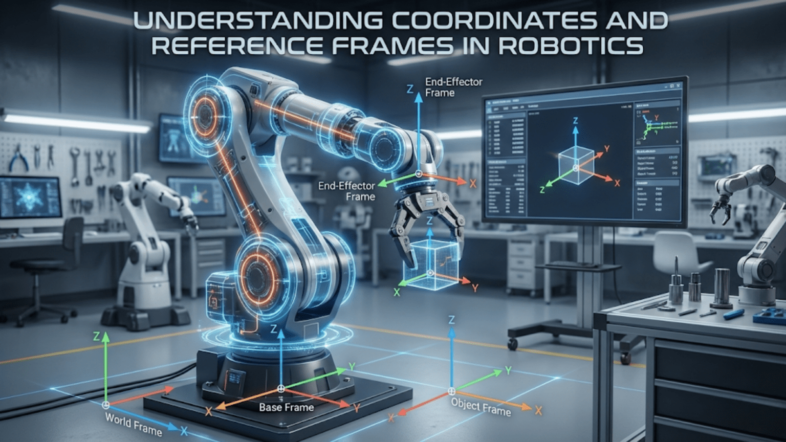
Fixed or world frames remain stationary in the environment, providing stable references for describing positions that do not move. A laboratory might establish world frame with origin at known location and axes aligned with building. Objects’ positions in world frame remain constant when those objects do not move. World frames provide common reference that multiple robots or systems can share, enabling coordination. When you tell a robot “go to position (5, 3) in world frame,” that location has unambiguous meaning regardless of where the robot currently is.
Body frames attach to moving objects, moving and rotating with those objects. Your mobile robot has body frame centered on the robot with X-axis pointing forward, Y-axis pointing left, and Z-axis pointing up. As the robot moves and rotates, its body frame moves and rotates too. Positions described in body frame remain constant relative to the robot even as the robot moves through world frame. The robot’s front camera is always at position (0.2, 0, 0.1) in body frame regardless of where the robot moves in world frame.
Sensor frames attach to sensors, describing positions from sensor’s perspective. A camera has frame with origin at the camera’s optical center and axes aligned with camera orientation. What the camera sees depends on positions in camera frame—objects with positive Z-coordinates (in front of camera) appear in images, while objects with negative Z-coordinates (behind camera) do not. Understanding sensor frames helps you interpret sensor data correctly and transform it into other useful frames.
End-effector frames for robot manipulators describe positions relative to the gripper or tool. When commanding robot arm to pick up an object, you often specify the object’s position in end-effector frame. The arm then calculates joint motions moving the end-effector frame to align with desired position. End-effector frames simplify manipulation tasks by letting you think about gripper position rather than all joint angles.
Why multiple frames? Different tasks naturally express in different frames. Navigation planning works best in world frame where obstacles and goals have fixed positions. Obstacle avoidance works well in body frame where you care about objects’ positions relative to robot. Manipulation naturally expresses in end-effector frame. Moving information between these frames through coordinate transformations lets you use whichever frame makes each task simplest while maintaining consistent overall behavior.
Coordinate Transformations: Moving Between Frames
The real power of reference frames emerges when you transform positions and orientations between different frames. These transformations enable robots to integrate information from multiple sources and coordinate actions across subsystems.
Translation transformations shift positions by fixed offset without rotation. If robot frame’s origin sits at position (3, 2) in world frame, translating from robot frame to world frame adds (3, 2) to robot-frame coordinates. A point at (1, 0) in robot frame sits at (4, 2) in world frame. This translation operation simply adds offset vector to coordinates, making it the simplest transformation type. Understanding translation helps you reason about how origin changes affect coordinate values.
Rotation transformations change coordinate directions by rotating axes without moving origin. If robot rotates 90 degrees counterclockwise from world frame, its X-axis points where world Y-axis points. Transforming coordinates from rotated robot frame to world frame requires applying rotation mathematics that updates coordinates to account for different axis orientations. Rotation transformations use trigonometric functions—point (x, y) rotated by angle θ transforms to (x·cos(θ) – y·sin(θ), x·sin(θ) + y·cos(θ)). While formulas seem complex, the concept remains straightforward: rotation changes which direction coordinates measure without moving points themselves.
Combined transformations handle both translation and rotation, which robots frequently need. Your robot sitting at some position with some orientation relative to world frame requires both translation and rotation to transform coordinates. Transformation mathematics combines translation and rotation into single operation efficiently calculating world coordinates from robot coordinates. This combined transformation forms the fundamental building block for describing spatial relationships in robotics.
Inverse transformations reverse coordinate transformations, converting from destination frame back to source frame. If you know transformation from robot frame to world frame, the inverse transformation converts from world frame to robot frame. Inverse transformations prove essential when you receive information in one frame but need it in another. If sensor reports object position in world frame, inverse transformation converts that position to robot frame where obstacle avoidance algorithms might need it.
Transformation chains combine multiple transformations when several frames relate hierarchically. A camera mounts on a pan-tilt unit, which mounts on a mobile robot base. Transforming from camera frame to world frame requires chaining three transformations: camera to pan-tilt, pan-tilt to robot base, robot base to world frame. Each transformation in the chain updates coordinates for one frame relationship, and composing all transformations gives complete camera-to-world transformation. This chaining enables complex robots with many frames to maintain consistent spatial relationships.
Homogeneous coordinates and transformation matrices provide mathematical machinery implementing transformations elegantly. Rather than separate translation and rotation calculations, homogeneous coordinates represent both in unified framework using 4×4 matrices for three-dimensional transformations. Matrix multiplication chains transformations naturally. While the mathematics involves linear algebra, understanding that transformation matrices encode both translation and rotation in structure that composes through multiplication helps you use transformation libraries effectively even without mastering matrix mathematics.
Practical Applications in Mobile Robots
Mobile robots provide clear examples where coordinate systems and transformations prove essential. Understanding how mobile robots use frames illustrates abstract concepts through concrete applications.
Odometry tracking estimates robot position by integrating wheel motions over time. As wheels rotate, odometry calculates how far robot moved and turned, updating robot position in world frame. This position estimate relies on coordinate transformations—wheel encoders measure in wheel frame, these transform to robot body frame, which transforms to world frame through current robot pose. Accumulating transformations over time produces position estimate in world coordinates.
Map representations describe obstacle locations in world frame so the map remains valid as the robot moves. When robot builds map through exploration, it records obstacle positions in consistent world coordinates. Later, when planning paths using the map, the robot transforms its current position to world frame, queries the map for obstacles, and plans motion. Map stability depends on consistent world frame—if world frame shifted arbitrarily, previously mapped obstacles would appear at wrong locations.
Path planning generates sequences of positions forming desired path from current robot position to goal. These paths typically plan in world frame where both current position and goal have fixed coordinates. However, executing the planned path requires transforming waypoints from world frame to robot frame to calculate required motor commands. The robot continually updates this transformation as it moves, ensuring it follows the intended world-frame path despite operating in body frame.
Sensor fusion combining multiple sensors requires transforming all sensor readings to common frame. If robot has front and rear distance sensors, their readings describe obstacles in different sensor frames. Combining readings to build complete obstacle map requires transforming sensor readings to common frame—typically robot body frame or world frame. Without proper transformations, obstacles detected by different sensors would not align properly, confusing obstacle avoidance algorithms.
Localization determines robot position in world frame from sensor observations. The robot observes landmarks with known world-frame positions and calculates where it must be to observe those landmarks at measured positions and angles. This localization problem essentially solves for transformation from world frame to robot frame that makes predicted landmark observations match actual sensor readings. Accurate localization depends on correct coordinate transformations relating world frame, robot frame, and sensor frames.
Practical Applications in Manipulator Arms
Robot manipulators showcase coordinate transformations’ power even more clearly than mobile robots because manipulators involve multiple moving frames for each joint.
Forward kinematics calculates end-effector position from joint angles. Each joint has associated frame that transforms based on joint angle. Chaining transformations from base through each joint to end-effector gives end-effector position and orientation in base frame. This transformation chain enables robot to know where its gripper is given all joint positions—essential for avoiding collisions and predicting motion outcomes.
Inverse kinematics solves the reverse problem: given desired end-effector position and orientation, calculate necessary joint angles. This inverse problem typically has no closed-form solution for complex arms, requiring numerical methods. However, the problem formulation itself relies on coordinate transformations—you specify desired end-effector pose in base frame, and inverse kinematics calculates joint angles achieving that pose by working backwards through transformation chain.
Workspace descriptions define regions end-effector can reach. These workspace descriptions use base frame coordinates to show which positions the manipulator can achieve. Understanding workspace in consistent base frame helps plan manipulation tasks and position the robot so objects fall within reach. Without coordinate frame formalism, describing complex three-dimensional workspace would be nearly impossible.
Object grasping requires knowing object position in end-effector frame. When planning grasp, you specify how gripper should align with object—typically requiring object to be centered in gripper with specific orientation. Transforming object position from camera frame or world frame into end-effector frame enables calculating gripper motion aligning it with object. The transformation from object position in world frame to end-effector frame guides the arm motion.
Tool frames extend beyond physical gripper to describe tool tips. If robot uses screwdriver, you care about screwdriver tip position, not gripper position. Tool frame transformation extends from gripper frame to tool tip. Controlling robot relative to tool frame rather than gripper frame makes tool use intuitive—you command tool tip position and orientation, and transformations through gripper frame to base frame determine necessary joint motions.
Force control in manipulation requires transforming forces between frames. If you push on end-effector, creating force in end-effector frame, that force creates torques at joints through transformation relating end-effector position to joint axes. Implementing compliant control where robot responds to external forces requires transforming sensed forces through appropriate frames to calculate proper responses. These force transformations extend spatial transformations into force domain.
Common Coordinate System Mistakes and Confusions
Understanding common errors helps you avoid frustration and debug problems when your coordinate transformations produce unexpected results.
Mixed frames error occurs when you combine coordinates from different frames without transforming them. If you add position in world frame to position in robot frame directly, the result is meaningless—like adding temperatures in Celsius to temperatures in Fahrenheit. This mistake produces nonsensical results that change as robot moves. Always verify coordinates are in same frame before combining them mathematically.
Wrong transformation direction applies inverse when you want forward transformation or vice versa. If you need to transform from frame A to frame B but apply transformation from B to A, results will be wildly incorrect. Keeping track of transformation direction—what source frame and destination frame are—prevents this error. Drawing diagrams showing frame relationships helps visualize correct transformation direction.
Incorrect rotation conventions create subtle bugs when different parts of system assume different rotation conventions. Some systems measure angles clockwise, others counterclockwise. Some start angle measurement from X-axis, others from Y-axis. These convention mismatches create systematic errors that might not be immediately obvious. Document rotation conventions explicitly and verify consistency across your robot’s codebase.
Unit inconsistencies between frames cause scaling errors. If world frame uses meters but robot frame uses centimeters, forgetting conversion creates factor-of-100 errors. Always track units explicitly and convert at frame boundaries. Modern software can help through type systems that track units, but vigilance prevents unit-related bugs that can be particularly frustrating to debug.
Forgetting frame motion when frames are not static leads to using outdated transformations. If you calculate transformation from robot frame to world frame, then robot moves, that transformation becomes invalid. You must recalculate transformations after frame motion. Mobile robots require continuous transformation updates as they move. Manipulator arms require recalculation whenever joints move. Treating transformations as static when they actually change creates position errors accumulating over time.
Gimbal lock and singularities in three-dimensional rotations cause problems near certain orientations. Representing three-dimensional rotations as three sequential rotations about axes (Euler angles) creates singularities where small orientation changes require large angle changes and rotation becomes ambiguous. Quaternions avoid gimbal lock but introduce different complexities. Understanding that three-dimensional rotation representations have subtleties helps you choose appropriate representations and handle special cases.
Tools and Libraries for Coordinate Transformations
Fortunately, you rarely implement coordinate transformations from scratch. Mature libraries handle mathematical details, letting you focus on using transformations correctly rather than implementing mathematics.
ROS (Robot Operating System) includes tf (transform) library specifically designed for managing coordinate frames in robotics. The tf library maintains frame relationships, automatically chains transformations, and provides high-level interfaces for common operations. ROS tf lets you define frame trees showing parent-child relationships between frames, and the library handles transformation calculations. This abstraction dramatically simplifies working with multiple frames in complex robots.
Python robotics libraries including NumPy for matrix operations, transforms3d for coordinate transformations, and PyKDL for kinematics provide transformation capabilities without full ROS. These lightweight libraries work well for projects not using ROS but needing coordinate transformation support. Documentation typically includes examples showing common transformation operations, helping you apply libraries to your specific needs.
MATLAB Robotics System Toolbox provides coordinate transformation functions integrated with broader robotics capabilities. If you develop algorithms in MATLAB before deploying to robots, toolbox functions let you prototype transformation-heavy code in familiar environment. Transformation functions closely mirror mathematical notation from robotics textbooks, easing translation from theory to implementation.
OpenCV computer vision library includes transformation functions relevant for camera-based robotics. Functions for camera calibration produce transformations between image coordinates and real-world coordinates. Pose estimation functions calculate coordinate transformations from visual features. If your robot uses vision, OpenCV’s transformation support integrates naturally with other vision processing.
Visualization tools help debug coordinate transformations by showing frames graphically. RViz visualizes ROS coordinate frames, letting you see frame relationships and verify transformations produce expected results. Matplotlib in Python can plot coordinate frames and trajectories. Visual verification catches errors that might be subtle in numerical output. When your transformation produces unexpected result, visualizing the frames often immediately reveals the problem.
Building Intuition About Coordinate Systems
Beyond learning technical details, developing intuitive understanding of coordinate systems helps you think clearly about spatial relationships without constantly referring to formulas.
Always draw pictures when working with coordinate systems. Sketching frames, positions, and transformations on paper forces you to think through spatial relationships explicitly. Many coordinate system confusions dissolve when you draw what frames look like and how they relate. This visual thinking complements mathematical formalism by engaging spatial reasoning abilities that might struggle with pure equations.
Think about coordinate transformations as “viewpoint changes.” Transforming from robot frame to world frame means “how would world frame describe what robot frame sees?” This viewpoint perspective makes transformations intuitive—you’re describing same physical reality from different perspectives. When transformation seems confusing, asking “what viewpoint change does this represent?” often clarifies what the transformation does.
Remember that transformations change descriptions, not reality. When you transform coordinates from one frame to another, the physical point’s location does not change—only how you describe it changes. This distinction between physical reality and coordinate description prevents confusion about what transformations accomplish. The point is where it is regardless of what coordinates you use to describe it.
Verify transformations with simple test cases. If you implement transformation from robot frame to world frame, test with points you can calculate by hand. Point (0, 0) in robot frame should transform to robot origin’s position in world frame. Point (1, 0) in robot frame should be one unit in front of robot in world frame. These sanity checks catch implementation errors before they cause problems in real applications.
Practice thinking in different frames fluently. When you observe object, practice describing its position in multiple frames—world frame, robot frame, sensor frame. This mental flexibility makes frame transformations feel natural rather than forcing conceptual jumps. Professional roboticists unconsciously translate between frames, which comes from extensive practice thinking about spatial relationships in multiple reference frames simultaneously.
Coordinate Systems in Three Dimensions
While two-dimensional examples aid initial understanding, most robotics operates in three dimensions, introducing additional complexity but following same fundamental principles.
Z-axis adds third dimension, typically vertical. Three coordinates (x, y, z) now describe positions in three-dimensional space. All two-dimensional concepts extend naturally—origins, axes, transformations all work the same way with added dimension. The additional dimension creates richer spatial relationships but does not fundamentally change how coordinate systems work.
Rotations in three dimensions become more complex than two-dimensional rotations. Three-dimensional objects can rotate around three different axes. Describing arbitrary three-dimensional rotation requires more information than single angle sufficing for two-dimensional rotation. Multiple rotation representations exist including rotation matrices (nine values), Euler angles (three angles), and quaternions (four values), each with advantages and disadvantages for different applications.
Right-hand rule extends to three dimensions, establishing consistent axis relationships. With right thumb along X-axis and index finger along Y-axis, middle finger points along Z-axis. This same rule applies locally within any frame, ensuring internal consistency. Robotics standards typically align Z-axis with “up” when possible, X-axis with “forward,” and Y-axis completes right-handed coordinate system.
Three-dimensional transformation matrices use 4×4 matrices in homogeneous coordinates. The mathematics extends naturally from two-dimensional 3×3 matrices but with additional computational complexity. Understanding conceptually that these matrices encode both three-dimensional rotation and three-dimensional translation suffices for using transformation libraries even without mastering matrix mathematics.
Gimbal lock and rotation singularities arise in three dimensions when certain rotation representations become ambiguous at specific orientations. Euler angles particularly suffer gimbal lock at ±90 degree pitch angles where yaw and roll rotations become indistinguishable. Quaternions avoid gimbal lock but require four values to represent three degrees of freedom. Libraries handle these details, but awareness that three-dimensional rotations have subtleties prevents confusion when orientation calculations behave unexpectedly near singularities.
Bringing It All Together
Coordinate systems and reference frames initially seem like abstract mathematical constructions but prove absolutely fundamental to robotics. Without these frameworks, robots could not describe where they are, where things are, or how to get from here to there. The formalism of coordinate systems transforms vague spatial descriptions into precise numerical specifications that robots can process mathematically.
The journey from confused beginner to comfortable user of coordinate systems proceeds through several stages. Initially, coordinate systems seem mysterious and transformations appear like magic formulas. With experience, simple transformations like translation become intuitive. Gradually, rotations and combined transformations make sense. Eventually, thinking in multiple frames simultaneously becomes natural, and coordinate systems become tools you use without conscious thought rather than obstacles you struggle with.
What makes coordinate systems learnable despite initial intimidation is their grounding in physical spatial relationships you understand intuitively. When you see coordinate transformation written as matrix multiplication, it seems abstract and difficult. When you visualize same transformation as “rotate these axes, then shift this origin,” it becomes concrete operation on spatial structure you can imagine. Maintaining connection between mathematical formalism and geometric intuition makes coordinate systems accessible even for people who struggle with pure mathematics.
Your robots will use coordinate systems constantly whether or not you understand them. Distance sensors report ranges in sensor frames. Motor encoders measure positions in joint frames. Navigation algorithms plan in world frame. Understanding how these frames relate and how your robot transforms between them changes you from passively following tutorials to actively designing robot behaviors with clear understanding of spatial relationships. This understanding enables debugging when transformations produce unexpected results, modifying robot code for new sensor configurations, and designing novel robot systems from first principles.
Start practicing coordinate system thinking with your next robot project. Explicitly identify what frames exist—world, robot body, sensors, and any others. Draw diagrams showing frame relationships. When your robot reports position, note what frame that position describes. When commanding motion, recognize what frame the command uses. This explicit attention to frames builds intuition far more effectively than passive reading. Through repeated application in actual projects, coordinate systems transform from confusing abstraction into intuitive tools you use naturally whenever describing spatial relationships in robotics.