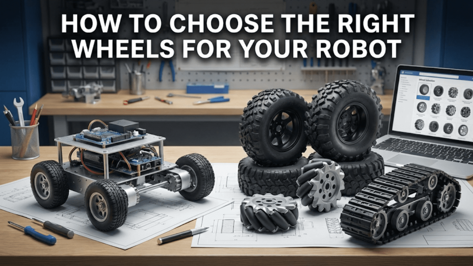
Choosing the right wheels for a robot requires matching four key parameters to your application: wheel diameter (determines speed, obstacle clearance, and torque requirements), wheel width (affects traction footprint and stability), tread material (determines grip on the specific surface), and wheel type (standard, omni, or mecanum—each enabling different movement capabilities). The wrong wheel choice is one of the most common reasons robots fail to perform as designed, making wheel selection a critical engineering decision rather than an afterthought.
Introduction
You’ve built the chassis, wired the motors, programmed the control algorithms, and you’re ready to put the robot on the ground for its first test. You attach some wheels you had lying around and watch as the robot spins its wheels on the smooth floor without moving, veers sharply to one side despite your best calibration efforts, or struggles to climb a slight ramp that should be well within its motor’s capability. The problem isn’t the code, the motors, or the electronics—it’s the wheels.
Wheels are the point where every mobile robot meets the real world. They are the mechanical interface between your carefully engineered drive system and the surface your robot needs to traverse. Get the wheel choice right and your robot moves exactly as designed: straight lines stay straight, turns are crisp and predictable, and the available motor torque actually translates into useful traction and motion. Get it wrong and no amount of software tuning will compensate for fundamental mechanical mismatch.
Despite this importance, wheel selection is often treated as an afterthought—grab whatever fits the motor shaft and move on. This article changes that approach by building a systematic, engineering-grounded understanding of what wheel properties actually matter, how each type of wheel performs, and how to match wheel specifications to the specific demands of your robot and environment.
The Physics of Wheels: What Makes a Wheel Work
Before diving into wheel types and specifications, understanding the fundamental physics of how wheels function reveals why each design parameter matters.
Rolling Contact and Traction
A wheel moves a robot by exerting a horizontal force on the ground—pushing backward against the ground, which by Newton’s third law pushes the robot forward. This only works if there is sufficient friction between the wheel and the ground to prevent slipping. The maximum horizontal force a wheel can exert before slipping is:
Maximum traction force = Normal force × Coefficient of friction (μ)<br>The normal force is the downward weight the wheel is carrying. The coefficient of friction depends on the wheel material and the ground surface—rubber on concrete might be 0.7–0.9, while a hard plastic wheel on smooth tile might be only 0.2–0.3.
This relationship has immediate practical implications:
A heavier robot has more traction, because higher normal force multiplied by any coefficient of friction gives more maximum traction force. This is why heavy robots rarely spin their wheels but can still be torque-limited in other ways.
Wheel material matters enormously. The difference between rubber (high μ) and hard plastic (low μ) can change your traction force by a factor of three or more on the same surface.
Tread width affects nothing fundamental about traction in simple theory—doubling the contact width doubles the area but halves the pressure, leaving the total friction force unchanged. In practice, wider treads distribute load better, reducing surface deformation and improving grip on soft surfaces. But on hard floors, a narrow wheel and a wide wheel of the same material have similar traction.
Rolling Resistance
As a wheel rolls, energy is consumed by the deformation of the wheel and surface material at the contact patch. This energy loss is rolling resistance, and it acts as a force opposing wheel motion:
Rolling resistance force = Normal force × Rolling resistance coefficient (Crr)Crr is much smaller than the traction coefficient—typically 0.002–0.02 for inflated rubber tires, 0.01–0.05 for solid rubber wheels, and up to 0.1 or more for soft foam wheels on hard surfaces. This means most of the wheel’s drive force goes into propulsion rather than overcoming rolling resistance—but the difference between wheel types still matters for battery life.
Inflated pneumatic wheels have the lowest rolling resistance (the air cushion deforms and springs back efficiently). Solid rubber wheels have moderate rolling resistance. Hard plastic wheels have low rolling resistance on hard surfaces. Soft foam wheels have high rolling resistance.
Wheel Diameter and Speed/Torque
Wheel diameter directly determines the relationship between motor shaft speed and linear robot velocity, and between motor torque and drive force:
Linear velocity = Motor RPM × π × Wheel diameter / 60

Drive force = Motor torque / (Wheel radius)A larger wheel gives higher linear speed for the same motor RPM but requires more torque to accelerate. A smaller wheel gives lower linear speed but more drive force from the same torque. This is why you always need to consider wheel diameter together with motor specifications—they are interdependent.
Example calculation:
Motor: 200 RPM at rated load
Wheel diameter: 65mm (radius = 32.5mm = 0.0325m)

Linear velocity = 200 × π × 0.065 / 60 = 0.34 m/s (about 1.2 km/h)

If motor produces 0.5 N·m torque:
Drive force = 0.5 / 0.0325 = 15.4 N

If the robot weighs 2 kg (about 20 N total weight):
Traction available (assuming μ = 0.6 on rubber, equal weight on two drive wheels):
Traction = 20N × 0.6 = 12 N per wheel if all weight on drive wheels

Drive force (15.4 N) > Available traction (12 N)
→ Motor has enough torque to spin wheels on this surface
→ Either increase weight, change surface, or reduce motor torqueThis calculation demonstrates why wheel diameter must be chosen together with motor specifications and robot weight—the complete system must be balanced.
Wheel Width and Stability
Wheel width determines the footprint stability of the robot. Wider wheels on the same axle spacing create a more stable stance—less likely to tip sideways. On soft surfaces (grass, sand, carpet), wider wheels also distribute load over a larger area, reducing sinkage and rolling resistance.
However, wider wheels on differential drive robots create more scrubbing friction during turns, because the outer and inner edges of the wheel trace different radii but the wheel rotates as a rigid body. This turn friction increases the motor torque required for turning and can cause the robot to track less accurately through turns.
Wheel Types: A Complete Taxonomy
Not all wheels are created equal. Different wheel architectures enable fundamentally different motion capabilities and represent different trade-offs between traction, maneuverability, and complexity.
Standard Fixed Wheels
The most common wheel type—a circular disc that rotates around a fixed axle perpendicular to the wheel plane. Standard wheels only move in one direction: the direction the wheel is pointing. They provide maximum traction in the rolling direction and rely on differential speed between left and right wheels (differential drive) to achieve turning.
Standard rubber wheels are the workhorses of wheeled robotics. Rubber treads provide excellent grip on most indoor surfaces. They come in many diameters (typically 40–150mm for small robots), widths, and hub configurations for different shaft sizes.
Hub types to know:
- Smooth bore hub: A plain hole through the center. Requires a set screw or press fit to attach to shaft. Simple but can slip under load.
- D-shaft hub: Matches the flat (D-shaped) shaft profile of many hobby motors. More positive grip than smooth bore with a set screw.
- Hex hub: Uses a hex-shaped bore for maximum positive engagement. Standard in FRC (FIRST Robotics Competition) and VEX systems.
- Servo horn adapter: Allows direct connection to a standard servo output. Common for small robots driven by continuous rotation servos.
Caster Wheels
Caster wheels are passive—they don’t drive the robot, they simply support weight while freely swiveling to track any direction of motion. In differential drive robots, the front and rear support points are typically caster wheels, allowing the driven rear wheels to steer the robot without the support wheels resisting directional changes.
Fixed caster: A standard wheel in a swivel bracket that pivots around a vertical axis offset from the wheel center. The offset causes the wheel to naturally trail behind the pivot point as the robot moves, automatically aligning with the direction of travel. Works well for smooth, flat surfaces.
Ball caster: A hardened ball captured in a socket, free to roll in any direction. Provides smooth, friction-free support with no directional alignment issues. Works excellently on hard floors but performs poorly on soft or uneven surfaces.
Selection criteria for casters: Match caster height to drive wheel height to keep the robot level. For carpet, ball casters work poorly—use swivel casters with wider wheels. For hard floors, ball casters are excellent.
Omni Wheels
Omni wheels (also called omnidirectional wheels) are one of the most interesting wheel designs in robotics. They look like a standard wheel but have a row of small passive rollers mounted around the perimeter, oriented perpendicular to the wheel’s rotation axis.
When driven, an omni wheel moves the robot in the wheel’s rolling direction exactly like a standard wheel—the main wheel drives forward/backward normally. But when force is applied in the direction perpendicular to rolling (laterally), the passive rollers spin freely, allowing the robot to slide sideways without resistance.
This property enables several important robotics capabilities:
Three-wheel holonomic drive: Three omni wheels arranged at 120° around the robot center allow full holonomic motion—the robot can move in any direction without rotating. Each motor combination produces a different motion vector, and their superposition enables arbitrary velocity in any direction plus rotation simultaneously.
Three-wheel holonomic drive motor mixing:
Given desired robot velocity: Vx (forward), Vy (sideways), Wz (rotation)
Wheel angles: 0°, 120°, 240° from robot front

Motor 1 speed = -Vx·sin(0°) + Vy·cos(0°) + Wz·R
Motor 2 speed = -Vx·sin(120°) + Vy·cos(120°) + Wz·R
Motor 3 speed = -Vx·sin(240°) + Vy·cos(240°) + Wz·R

Where R = distance from robot center to wheel contact pointFour-wheel holonomic drive (X configuration): Four omni wheels at 45° to the robot’s axis create an X-drive configuration. This produces holonomic motion and is commonly used in VEX Robotics competition robots.
Reduced turn scrubbing: Even on differential drive robots, replacing one side’s fixed drive wheels with omni wheels reduces the friction penalty during turns, allowing smoother rotation without fighting wheel scrub.
Limitations of omni wheels:
- No lateral traction: The rollers that enable free lateral movement also mean the robot cannot resist lateral forces—a side push will slide the robot sideways. On inclined surfaces, the robot will slide downhill laterally.
- Higher rolling resistance: The multiple rollers introduce more friction than a single smooth wheel tread.
- Reduced performance on carpet: The small rollers snag on carpet fibers, making omni wheels primarily effective on hard floors.
- Vibration: As rollers transition through the contact point, they create a characteristic “bumpy” feel and sound, which can affect sensor readings if not damped.
Mecanum Wheels
Mecanum wheels (also called Ilon wheels or Swedish wheels) are the most mechanically sophisticated common wheel type. Like omni wheels, they have passive rollers around the perimeter—but unlike omni wheels, the mecanum rollers are oriented at 45° to the wheel’s rotation axis.
This 45° angle creates a remarkable property: when the wheel rolls forward, the passive rollers generate a force component both in the wheel’s rolling direction AND at 45° to it. By combining four mecanum wheels (two “left-handed” and two “right-handed” variants in an X configuration), a robot can generate force in any horizontal direction without reorienting:
Mecanum wheel drive mixing (standard X configuration):
Wheel positions: Front-Left, Front-Right, Rear-Left, Rear-Right
Wheel chirality: FL and RR are "left-hand" (rollers \), FR and RL are "right-hand" (rollers /)

Motion commands:
Forward:     FL+, FR+, RL+, RR+ (all forward)
Backward:    FL-, FR-, RL-, RR- (all backward)
Turn left:   FL-, FR+, RL-, RR+ (left wheels back, right wheels forward)
Turn right:  FL+, FR-, RL+, RR- (left forward, right back)
Strafe left: FL-, FR+, RL+, RR- (front-left and rear-right back)
Strafe right: FL+, FR-, RL-, RR+ (front-left and rear-right forward)
Diagonal: Combinations of the aboveIn code, mecanum drive mixing looks like this:
// Mecanum wheel drive mixing
// Inputs: forward (-1 to +1), strafe (-1 to +1), rotate (-1 to +1)

void mecanumDrive(float forward, float strafe, float rotate) {
  // Calculate individual wheel speeds
  float frontLeft  =  forward + strafe + rotate;
  float frontRight =  forward - strafe - rotate;
  float rearLeft   =  forward - strafe + rotate;
  float rearRight  =  forward + strafe - rotate;

  // Find the maximum value to normalize if needed
  float maxSpeed = max(max(abs(frontLeft), abs(frontRight)),
                       max(abs(rearLeft), abs(rearRight)));

  // Normalize to keep all values within -1 to +1
  if (maxSpeed > 1.0) {
    frontLeft  /= maxSpeed;
    frontRight /= maxSpeed;
    rearLeft   /= maxSpeed;
    rearRight  /= maxSpeed;
  }

  // Convert -1..+1 range to PWM values (0..255)
  // Assuming motors can reverse direction based on sign
  setMotor(FRONT_LEFT,  (int)(frontLeft  * 255));
  setMotor(FRONT_RIGHT, (int)(frontRight * 255));
  setMotor(REAR_LEFT,   (int)(rearLeft   * 255));
  setMotor(REAR_RIGHT,  (int)(rearRight  * 255));

  // Debug output
  Serial.print("FL:"); Serial.print(frontLeft);
  Serial.print(" FR:"); Serial.print(frontRight);
  Serial.print(" RL:"); Serial.print(rearLeft);
  Serial.print(" RR:"); Serial.println(rearRight);
}

void loop() {
  // Example: move diagonally forward-right while rotating
  mecanumDrive(0.8, 0.5, 0.0);
  delay(2000);

  // Strafe left at full speed
  mecanumDrive(0.0, -1.0, 0.0);
  delay(2000);

  // Rotate in place
  mecanumDrive(0.0, 0.0, 0.5);
  delay(2000);
}Where mecanum wheels excel:
- Warehouse robots and logistics AGVs that need to maneuver in tight spaces without turning
- Robots in competitions requiring maximum maneuverability (FIRST Robotics is full of mecanum robots)
- Service robots in environments with narrow aisles
- Any application requiring precise positioning without complex turning maneuvers
Mecanum limitations:
- Cost: Mecanum wheels are significantly more expensive than standard wheels
- Efficiency: The 45° roller forces partially cancel each other, making forward motion less efficient than standard wheels. Typically 70% efficient in forward/backward compared to standard wheels
- Lateral force resistance: Like omni wheels, mecanum robots cannot resist lateral forces and will slide sideways on slopes
- Floor surface sensitivity: Small rollers don’t perform well on carpet or rough surfaces
- Vibration and noise: The roller transition creates vibration, particularly noticeable at speed
- Mechanical complexity: Eight motors (four wheels, with four-wheel drive being standard) and precise wheel alignment requirements add complexity and cost
Tracks and Tank Treads
While not wheels in the traditional sense, tracked drive systems compete with wheeled systems for certain robotics applications and deserve comparison.
Tracks distribute the robot’s weight over a long ground contact area, dramatically reducing ground pressure. This allows tracked robots to traverse soft terrain (mud, sand, snow) and climb obstacles that would immobilize wheeled robots. Tank-style differential steering turns tracks the same way differential drive turns wheels: by driving one side faster than the other or in opposite directions.
Advantages over wheels for rough terrain: Better obstacle climbing (can ride over obstacles up to half the track height), better soft terrain performance, more stable on slopes (low center of gravity, wide footprint).
Disadvantages versus wheels: Higher friction during turns (the entire track scrubs against the ground), higher mechanical complexity (many more moving parts), higher rolling resistance on smooth surfaces, louder operation, more difficult to implement odometry.
For indoor robotics on smooth floors, wheels are almost always superior. For outdoor robotics in unstructured terrain, tracked systems are often necessary.
Key Specifications: What to Look at When Buying Wheels
When selecting wheels for a specific robot, several specifications determine fit and performance.
Diameter
Wheel diameter is typically measured as the outer diameter of the tread surface. Common sizes for small robots:
- 40–65mm: Very small robots, tight spaces, high torque/low speed applications
- 65–100mm: The sweet spot for most differential drive robots. Good ground clearance, reasonable speed with typical hobby motors
- 100–150mm: Larger robots, faster speeds, higher ground clearance for rough surfaces
- 150mm+: Large robots, outdoor use, significant obstacle clearance
Calculate your target robot speed with the chosen diameter and your motor’s RPM before purchasing to ensure the combination gives the speed you want.
Hub Bore and Shaft Compatibility
The wheel must fit your motor shaft. Common shaft standards:
| Shaft Type | Description | Common Use |
|---|---|---|
| 3mm smooth round | Small hobby motors, N20 gearmotors | Mini robots, precision builds |
| 4mm smooth round | Medium hobby motors | Common micro gearmotor size |
| 5mm smooth round | Standard hobby gearmotor output | Most common for 12V DC motors |
| 6mm D-shaft | Flat ground on one side | Pololu gearmotors, many hobby motors |
| 6mm hex | Hexagonal shaft profile | VEX, some premium motors |
| 1/4″ (6.35mm) | Imperial motors, some gearboxes | US-sourced motors |
| Servo spline | 25-tooth or 24-tooth spline | Direct servo mounting |
Shaft bore mismatch is one of the most common ordering mistakes. Measure your motor shaft diameter before selecting wheels, and confirm the hub type (smooth bore + set screw, D-shaft, hex, or spline) matches your shaft profile.
Tread Material
Tread material determines grip and rolling resistance on your specific surface:
Silicone/rubber compound: Highest grip on most surfaces. Slightly higher rolling resistance. Best choice for indoor floors, competition surfaces, and anywhere traction is critical.
Polyurethane foam: Very high grip, compressible, excellent vibration absorption. Used in sumo robot wheels and high-traction applications. Higher rolling resistance, wears faster.
Hard rubber: Moderate grip, lower rolling resistance than soft rubber. Good general-purpose choice.
Hard plastic (polypropylene, nylon): Lowest rolling resistance on hard floors, low friction. Used for casters and support wheels where traction isn’t needed. Poor choice for drive wheels on smooth floors.
Knobby rubber (off-road tread): High grip on dirt, grass, and gravel. Reduces grip on smooth floors compared to smooth rubber. Higher rolling resistance.
Axle Length and Chassis Compatibility
The wheel must fit on your robot’s chassis with appropriate spacing. Consider:
- Hub width vs. available space between frame members
- Shaft length protruding from motor vs. wheel hub depth
- Need for shaft collars or spacers to prevent axial movement
- Wheel scrub clearance (enough gap between wheel and chassis to prevent rubbing)
Matching Wheels to Robot Type
Different robot architectures have specific wheel requirements. Here’s how to approach selection for the most common configurations.
Differential Drive Robots
The most common mobile robot configuration: two driven wheels on a common axis, plus one or two passive caster wheels for support. Wheel selection for differential drive:
Drive wheels: Rubber-tread, diameter matched to motor RPM for desired speed, D-shaft or hex hub matching motor output shaft. Width: wider gives more grip but more turning friction. Typically 20–40mm wide for small robots.
Caster wheels: Height must match drive wheel height (measure carefully). Ball casters work excellently on hard floors; swivel casters are better for carpet or outdoor use. Caster position (front, rear, or both) affects stability—placing caster(s) at the opposite end from the center of gravity keeps the robot level.
Critical alignment: Both drive wheels must be identical (same diameter, same tread compound) to prevent constant drift. Even small diameter differences cause the robot to curve consistently in one direction.
Four-Wheel Drive Robots
Four driven wheels provide excellent traction and payload capacity. The challenge: with a rigid chassis, all four wheels must be on the ground simultaneously. Any chassis twist or uneven surface will cause one wheel to lift, losing traction.
Solutions:
- Use a chassis with deliberate flex to allow all four wheels to conform to the surface
- Add a passive rocker mechanism between front and rear axle pairs
- Use wide, slightly compressible rubber wheels that conform slightly to surface irregularities
- Deliberately allow slight rocker by mounting one axle pair on a pivoting beam
All four wheels should be identical for predictable behavior.
Holonomic Robots (Omni or Mecanum)
Omni wheel drive (3 or 4 wheels): All three/four wheels must be identical. Wheel spacing and angle must match the control algorithm’s geometric assumptions exactly. Inexpensive omni wheels with poor roller quality produce more vibration and less predictable lateral sliding—worth investing in quality for accurate holonomic control.
Mecanum drive: Left-hand and right-hand wheels must be correctly oriented (rollers tilting inward vs. outward in a standard X configuration). A common beginner mistake is installing mecanum wheels in the wrong orientation, causing the robot to strafe when you command forward, or to rotate when you command strafe. Double-check wheel chirality before installation.
Mecanum wheels require all four motors and drive electronics to be precisely matched for accurate straight-line driving—any speed imbalance between wheels causes drift. A PID heading controller using a gyroscope (as discussed in the article on closed-loop control) dramatically improves straight-line performance.
Competition Robots
Competition robots face specific constraints: weight limits, field surface specifications, and performance demands.
FIRST Robotics Competition (FRC): The aluminum VEX and REV wheel systems are standard. Colson wheels (solid rubber, flat tread, very durable) are used extensively. Pneumatic tires provide excellent traction and suspension for the bumpy FRC field. West Coast Drive (six-wheel drive with center wheel dropped slightly) is the dominant drivetrain, providing reliable ground contact on all surfaces.
VEX Robotics: VEX wheels with 393 motors or V5 motors. Standard 4″ VEX traction wheels or flex wheels for grip events. Omni wheels at strategic positions to reduce turning friction in tank-style drives.
Sumo robots: Maximum traction is the primary requirement—heavy polyurethane foam or rubber wheels with large contact area and very soft compound. Low-profile chassis to lower center of gravity.
Calculating Wheel Diameter: A Complete Example
Let’s work through a complete wheel selection calculation for a real robot scenario.
Requirements:
- Autonomous indoor mobile robot
- Target forward speed: 0.5 m/s
- Available motor: 12V DC gearmotor, 150 RPM at rated load, 6mm D-shaft
- Robot weight: 1.5 kg
- Surface: smooth vinyl floor
- Drive configuration: differential drive, two motors
Step 1: Calculate required wheel diameter for target speed
Target speed = 0.5 m/s
Motor speed = 150 RPM = 2.5 RPS

Required wheel circumference = 0.5 m/s ÷ 2.5 RPS = 0.2 m
Required wheel diameter = 0.2 m ÷ π = 0.064 m = 64 mmA 65mm diameter wheel is close to ideal—very close to the calculated 64mm.
Step 2: Verify traction with chosen wheel
Robot weight = 1.5 kg × 9.81 m/s² = 14.7 N
Weight per drive wheel (assuming 70% weight on drive wheels, 2 wheels):
Normal force per wheel = 14.7 × 0.7 / 2 = 5.1 N

Coefficient of friction (rubber on vinyl floor): μ ≈ 0.6
Traction force per wheel = 5.1 × 0.6 = 3.1 N
Total traction = 3.1 × 2 = 6.2 NStep 3: Verify motor torque doesn’t exceed traction
Motor stall torque (typical for this class): ~0.5 N·m
Max drive force = 0.5 N·m ÷ (0.0325 m radius) = 15.4 N per motor

15.4 N available >> 6.2 N traction limit
→ Motor has more than enough torque; traction will be the limiting factor
→ Robot cannot spin wheels at rated motor torque (good — this means full traction)
→ At rated speed, torque is much less than stall torque, so actual drive force is lower

This is acceptable — the robot has adequate traction margin.Step 4: Select specific wheel
Criteria confirmed: 65mm diameter, 6mm D-shaft hub, rubber tread, indoor use.
A Pololu 65mm wheel or equivalent with 6mm D-shaft adapter fits perfectly. Width of 25–30mm gives adequate traction footprint without excessive turning friction.
Practical Wheel Mounting and Common Mistakes
Even the right wheel fails if improperly mounted. Common mechanical issues:
Set Screw Loosening
Set screws that secure wheels to shafts tend to work loose under vibration. Solutions:
- Apply a small drop of thread-locking compound (Loctite 222 for removable, 243 for permanent) to the set screw before installation
- Use two set screws at 90° to each other
- Use hex or D-shaft instead of smooth round bore to rely on positive shaft engagement rather than friction from a set screw alone
Axial Play (Wheel Sliding Along Shaft)
Without axial constraint, wheels can slide sideways along the shaft, causing misalignment and inconsistent track width. Fix with shaft collars on both sides of the wheel hub, or design the chassis so the wheel is captured between frame members.
Bent Axles
Cantilevered axles (shaft protruding from motor only on one side) experience bending loads from the wheel’s weight and driving forces. For heavy robots or large wheels, add a bearing support on the outboard side of the wheel to eliminate cantilever bending. Even a simple 3D-printed or aluminum bracket with a ball bearing supporting the shaft tip dramatically reduces shaft deflection and bearing wear.
Wheel Wobble
Wheels that wobble (run out) make the robot vibrate, wear out motor bearings faster, cause inconsistent encoder readings, and make the robot harder to control precisely. Causes include bent motor shafts, hubs installed off-center, or low-quality wheels with poor manufacturing tolerances. Check for runout by spinning the wheel and watching the tread surface from above—it should trace a consistent circle with no side-to-side wobble.
Summary
Wheel selection is a multi-dimensional engineering decision that connects directly to robot performance. The key parameters—diameter, width, tread material, hub type, and wheel architecture—each have specific effects on robot speed, traction, maneuverability, stability, and efficiency.
Standard rubber wheels remain the right choice for the vast majority of differential drive robots operating on indoor surfaces: high traction, simple control, low cost, and predictable behavior. Omni wheels enable holonomic motion at the cost of lateral force resistance and carpet performance. Mecanum wheels provide the most sophisticated maneuverability but at significant cost in efficiency, complexity, and surface sensitivity. Tracks address truly rough terrain at the cost of turning efficiency and rolling resistance on smooth floors.
The selection process starts with calculating the diameter needed for your target speed and motor specifications, verifying traction is adequate without exceeding motor output, matching the hub to your motor shaft, selecting tread material appropriate to your floor surface, and finally choosing the wheel architecture that provides the maneuverability your application requires.
Wheel selection done right means every motor revolution actually moves your robot exactly where you intended. Wheel selection done wrong means fighting mechanical problems through the entire software development and testing process—problems that no amount of code can fully fix. Take the time to get it right before the first wheel turns.
The next article explores gear ratios—the mechanical multipliers that transform motor speed and torque into the wheel speed and force your robot actually needs, and the principles behind designing and selecting gearing for any mechanical power transmission application.