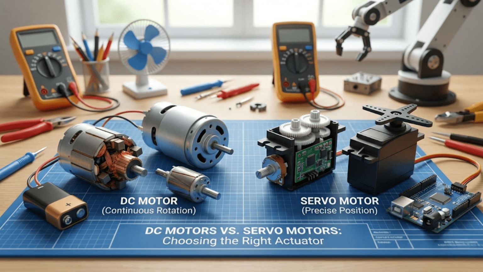
DC motors spin continuously when powered and require external encoders, gearboxes, and H-bridge drivers to achieve controlled speed and direction, making them ideal for wheel drive, pumps, and fans where continuous rotation matters—while servo motors integrate a DC motor, gearbox, position sensor, and control electronics into a self-contained package that moves to and holds commanded angles, making them ideal for robot joints, grippers, and steering where precise positioning matters. Choosing between them depends primarily on whether your application needs continuous rotation (DC motor) or controlled angular positioning (servo motor).
You’re designing a new robot and face the choice that confronts every robotics builder at some point: should this actuator be a DC motor or a servo motor? The decision seems simple at first—DC motors spin, servo motors position—but real projects quickly reveal complications. What if you need a DC motor to hold a precise position? What if you need a servo that rotates continuously? What if you need both high speed and precision? What if cost or weight dominates the decision? What if you’re building a robot arm versus a wheeled platform versus a gripper versus a conveyor mechanism?
These questions don’t have universal answers. DC motors and servo motors each excel in specific applications and struggle in others. The experienced roboticist doesn’t default to one type or the other—they analyze requirements and match actuator characteristics to application demands. Sometimes the right answer is a plain DC motor with an encoder. Sometimes it’s a hobby servo with no additional hardware. Sometimes it’s a brushless motor with an ESC. Sometimes it’s a combination of types on the same robot, each handling the task it does best.
This article provides the complete framework for making that decision well. We examine both actuator types in depth—how they work, what specifications matter, what they cost in real projects, where they excel, and where they fail. We present direct side-by-side comparisons for the scenarios robotics builders actually encounter: mobility systems, robot arms, grippers, steering, camera mounts, and more. We provide a practical decision framework and code examples showing how the same task looks when implemented with each actuator type. By the end, you’ll have the knowledge to choose confidently rather than guessing.
DC Motors: Strengths, Weaknesses, and Specifications
Understanding DC motors as actuators—not just as components—requires examining what they actually provide and what they don’t.
What DC Motors Actually Give You
A bare DC motor provides one thing: shaft rotation proportional to applied voltage. No position feedback, no gearbox, no speed regulation, no reversal capability built in. Everything else—direction control, speed regulation, position feedback, torque multiplication—requires additional components.
The complete DC motor system for robotics typically includes:
- DC motor (the rotating element)
- Gearbox (converts high speed/low torque to low speed/high torque)
- H-bridge driver (enables bidirectional speed control)
- Encoder (optional but essential for position/speed feedback)
- Microcontroller and control code (to use the encoder data)
This complexity is a real cost—both in money and in design effort. A typical gear motor with encoder costs $8-30. Adding an H-bridge driver adds $3-8. Writing and tuning encoder-based speed control takes significant development time. The total system is genuinely more complex than plugging in a servo.
But that complexity buys something: flexibility. You choose the exact motor, gearbox ratio, encoder resolution, driver current rating, and control algorithm independently. You’re not constrained by a servo manufacturer’s choices for any of those parameters.
Key DC Motor Specifications
No-load speed: RPM with no mechanical load—the maximum speed the motor achieves. Actual operating speed will be lower under load.
Stall torque: Torque produced when the shaft is held completely still (maximum torque, at zero RPM). This is the motor’s peak force capability.
No-load current: Current drawn with no mechanical load—the baseline consumption to overcome internal friction.
Stall current: Current drawn at stall—often 5-10× no-load current. Your motor driver must handle this without damage.
Rated voltage: The voltage the motor is designed to operate at continuously. Running significantly above rated voltage reduces motor life.
Power: Rated power = voltage × current at the optimal operating point (roughly halfway between no-load and stall conditions).
Efficiency: Ratio of mechanical output power to electrical input power—typically 50-80% for quality motors, lower for budget versions.
Where DC Motors Excel
Continuous high-speed rotation: Wheels, propellers, pumps, fans, conveyors—anything that needs to spin fast and keep spinning. DC motors are designed for this. Servo motors are explicitly not designed for continuous rotation (standard ones, anyway).
Variable speed over a wide range: With PWM control, DC motors provide smooth speed variation from nearly stopped to full speed across a much wider range than servos.
High power density: Large DC motors pack extraordinary power into compact packages. Industrial DC motors can deliver kilowatts from surprisingly small frames. Hobby servo motors top out at a few dozen watts.
Efficiency at high loads: Quality DC motors operating near their optimal point (typically 50-60% of stall torque) achieve 70-85% efficiency—significantly better than many servo designs under heavy load.
Cost at scale: Individual motor-only units are often cheaper than equivalent servo packages, especially at larger sizes and quantities.
Where DC Motors Struggle
Position control requires external hardware: Without encoders and control loops, a DC motor has no idea where its shaft is. Position control requires the encoder, the feedback loop, and the tuning—none of which comes for free.
Variable load causes speed variation: A plain DC motor speeds up and slows down as load changes. Without speed feedback, driving up a hill slows your robot; driving down speeds it up. Compensation requires encoders and PID control.
Direction control needs an H-bridge: DC motors run in only one direction when connected directly to a battery. Reversal requires an H-bridge driver, adding cost and complexity.
Small motors often sacrifice quality: The cheap gear motors used in many beginner kits have poor gearbox quality (high backlash), weak shafts, and noisy operation. Budget motors and quality motors differ dramatically.
Servo Motors: Strengths, Weaknesses, and Specifications
Servo motors—specifically hobby-type RC servos—represent a pre-integrated solution that trades flexibility for simplicity.
What Servo Motors Actually Give You
A standard hobby servo provides everything integrated:
- DC motor (usually small and high-speed)
- Multi-stage plastic or metal gearbox (20:1 to 300:1 reduction)
- Potentiometer position sensor
- Control electronics (PWM decoder, error amplifier, motor driver)
- Mechanical output horn and mounting provisions
Connect three wires (power, ground, signal), send a PWM command, and the servo moves to the commanded angle and holds it. The position feedback loop runs internally at high speed. You never write feedback code—it’s all done inside the servo.
This integration is the servo’s primary value proposition: enormous capability reduction in system complexity. For positional control applications, a servo replaces a complete subsystem.
Key Servo Motor Specifications
Torque: Specified in kg·cm or oz·in at rated voltage. A 3 kg·cm servo produces 3 kg of force at 1 cm from the shaft center. Double the lever arm, half the effective force. This is the most critical specification for load-bearing applications.
Speed: Usually specified as seconds per 60 degrees of travel (e.g., 0.15 sec/60°). Lower number = faster servo. Convert to degrees/second: (60°) ÷ (time in seconds) = deg/s.
Operating voltage: Most standard servos operate at 4.8-6V. High-voltage servos operate at 6-8.4V for more torque and speed. Running a standard servo at too high voltage risks overheating and failure.
Dead band: The minimum position error that triggers motor activation—typically 1-5 microseconds of pulse width, corresponding to ~0.1-0.5°. Smaller dead band = better precision but more jitter.
Gear material: Plastic gears: lighter, quieter, cheaper, but fail under shock loads or sustained high torque. Metal gears: heavier, louder, more expensive, but dramatically more durable.
Bearing type: Plastic bushings vs. ball bearings. Ball bearings reduce slop and wear, important for heavily loaded joints.
Where Servo Motors Excel
Precise angular positioning with zero additional hardware: The servo’s internal feedback loop provides position control without encoders, control loops, or driver circuits beyond a PWM-capable pin. For joints, grippers, and steering, this simplicity is extraordinary.
Position holding under load: The internal feedback loop actively fights disturbances. Push a servo arm, and it pushes back. This active holding maintains joint positions in robot arms without constant power consumption.
Beginner accessibility: Three wires, one function call (myServo.write(90)), and you have working position control. The complexity barrier is essentially zero compared to encoder-based DC motor control.
Small size and weight for torque provided: The integrated gearbox makes servos compact. A 60g servo producing 10 kg·cm torque would require a much heavier separate motor + gearbox combination.
Safety: Servo motors naturally stall without damage at reasonable loads (within ratings). They have built-in current limiting through the internal control electronics.
Where Servo Motors Struggle
No continuous rotation (standard servos): The potentiometer physically limits standard servos to ~180° travel. Forcing beyond the mechanical limit damages the sensor or gearbox. Continuous rotation servos sacrifice position feedback entirely.
Limited torque range: Hobby servos top out around 40-60 kg·cm. Industrial servo motors can deliver much higher torques, but at dramatically higher cost—at that point, the servo vs. DC motor comparison involves entirely different products.
Fixed operating voltage: Standard servos want 4.8-6V. Many robot power systems run at 7.4V (2S LiPo) or 12V—requiring voltage regulators that add complexity and cost.
Gear backlash and wear: Even quality servo gearboxes have some backlash (play between gears). Under repeated load reversals, gears wear. Plastic gearboxes on cheap servos fail dramatically under shock loads.
No speed feedback: You can command a servo to a position, but you can’t directly read how fast it’s moving or control its velocity profile (without digital servos and special interfaces).
Positional resolution limited by PWM: Standard servo resolution is approximately 0.5-1° depending on PWM controller resolution. For finer positioning, dedicated servo controllers with higher PWM resolution are needed.
Direct Comparisons: Application by Application
Rather than abstract specifications, let’s examine specific robotics applications and evaluate both actuator types directly.
Application 1: Mobile Robot Drive (Wheels)
The task: Drive two wheels to move a robot across varied terrain at controlled speeds.
DC Motor Approach:
// Differential drive with DC motors and encoders
// Precise speed control, can detect slip, works on varied terrain

#include <AccelStepper.h>  // Or custom encoder-based control

const int ENA = 9, IN1 = 2, IN2 = 3;  // Left motor
const int ENB = 10, IN3 = 4, IN4 = 5; // Right motor

volatile long leftCount = 0, rightCount = 0;
float targetSpeedLeft = 20.0;  // cm/s
float targetSpeedRight = 20.0;

// Speed control PID (simplified)
void driveAtSpeed(float leftCms, float rightCms) {
  // Measure actual speed from encoders
  // Apply PID to maintain target speed
  // Compensates for hills, friction changes, battery drain
  // Robot travels at consistent speed regardless of conditions
}Verdict for drive wheels: DC motors with encoders win decisively.
- Continuous rotation is exactly what wheels need
- Speed feedback handles varying terrain reliably
- Much higher speeds achievable
- Encoder-based control makes navigation accurate
Continuous Rotation Servo Approach:
#include <Servo.h>
Servo leftWheel, rightWheel;

void setup() {
  leftWheel.attach(9);
  rightWheel.attach(10);
}

void driveForward(int speed) {
  // speed: 0-100 (rough percentage)
  int leftPWM = map(speed, 0, 100, 1500, 2000);
  int rightPWM = map(speed, 0, 100, 1500, 1000); // Reversed for opposite side
  leftWheel.writeMicroseconds(leftPWM);
  rightWheel.writeMicroseconds(rightPWM);
  // No speed feedback - varies with load and battery
}Verdict for drive wheels with continuous servos: Works for simple robots, but:
- No speed feedback—robot slows on inclines
- Lower top speed than equivalent DC motors
- Higher cost per unit of speed/power
- Acceptable for: very simple robots, beginner platforms, servo-based kits
Application 2: Robot Arm Joints
The task: Move and hold an arm joint at specific angles under gravity load.
Servo Approach:
#include <Servo.h>
Servo elbowJoint;

void setup() {
  elbowJoint.attach(9);
}

void setElbowAngle(int degrees) {
  degrees = constrain(degrees, 0, 180);
  elbowJoint.write(degrees);
  // Servo holds this angle against gravity automatically
  // No additional code needed
}

void loop() {
  setElbowAngle(45);  // Move to 45° and hold
  delay(2000);
  setElbowAngle(90);  // Move to 90° and hold
  delay(2000);
}Verdict for arm joints: Servo motors win for most hobby/educational robots.
- Position holding is built-in—no feedback code
- Angular positioning is the servo’s purpose
- Three-wire interface is trivially simple
- Torque sufficient for light-to-medium arms
DC Motor Approach for Arm Joint:
// Requires: DC motor + encoder + H-bridge + PID control code
// Significant additional complexity

volatile long encoderPosition = 0;
float targetAngle = 0;
float Kp = 2.0, Ki = 0.01, Kd = 0.5;
float integral = 0, lastError = 0;

void positionControlLoop() {
  float currentAngle = encoderPosition * (360.0 / pulsesPerRev);
  float error = targetAngle - currentAngle;
  integral += error;
  float derivative = error - lastError;
  float output = Kp*error + Ki*integral + Kd*derivative;
  lastError = error;
  setMotorPWM(output);  // Apply to H-bridge
}
// Works well but requires much more code and hardwareVerdict for arm joints with DC motors: Viable but adds complexity that servos avoid.
- Choose DC motors + encoders when: torque requirements exceed servo specs, need speed control during movement, require sub-degree positioning accuracy
- Choose servos when: simplicity matters, torque is within servo specs, rapid development is valued
Application 3: Gripper Mechanism
The task: Open and close a gripper to grasp and release objects.
Servo Approach:
#include <Servo.h>
Servo gripper;

const int OPEN_ANGLE = 160;
const int CLOSED_ANGLE = 60;
const int contactPin = 2;

void setup() {
  gripper.attach(9);
  pinMode(contactPin, INPUT_PULLUP);
}

bool closeGripper() {
  for (int angle = OPEN_ANGLE; angle >= CLOSED_ANGLE; angle--) {
    gripper.write(angle);
    delay(10);
    if (digitalRead(contactPin) == LOW) {
      // Object contacted - stop closing
      return true;
    }
  }
  return false;
}

void openGripper() {
  gripper.write(OPEN_ANGLE);
  delay(500);
}Verdict for grippers: Servos excel.
- Slow, controlled movement suits grasping
- Position holding grips objects without continuous power draw
- Contact sensing integration is simple
- Fingertip force proportional to commanded angle past contact
DC Motor Approach for Gripper:
- Needs H-bridge for direction control
- Needs current monitoring or contact sensor to detect grip
- Stall current detection replaces contact sensor (advanced but elegant)
- Better for: force-controlled grasping, high-speed open/close cycles, very high grip forces
Application 4: Vehicle Steering
The task: Turn front wheels to steer an autonomous car-type robot.
Servo Approach:
#include <Servo.h>
Servo steeringServo;

const int CENTER = 90;
const int MAX_LEFT = 60;
const int MAX_RIGHT = 120;

void setup() {
  steeringServo.attach(9);
  steeringServo.write(CENTER);
}

void steer(int angle) {
  // angle: negative=left, 0=straight, positive=right
  int servoAngle = map(angle, -30, 30, MAX_LEFT, MAX_RIGHT);
  servoAngle = constrain(servoAngle, MAX_LEFT, MAX_RIGHT);
  steeringServo.write(servoAngle);
}

void loop() {
  // Proportional steering based on error
  float lineError = getLineError();  // -1.0 to +1.0
  steer((int)(lineError * 30));
}Verdict for steering: Servo motors are the natural fit.
- Steering requires position (angle), not continuous rotation
- Self-contained position holding maintains steering angle
- Servo is literally how real RC cars steer
- Simple, reliable, exactly the right tool
Application 5: Camera Pan-Tilt System
The task: Point a camera or sensor in two axes under computer control.
Servo Approach (standard choice):
#include <Servo.h>
Servo panServo, tiltServo;

void setup() {
  panServo.attach(9);
  tiltServo.attach(10);
  panServo.write(90);
  tiltServo.write(90);
}

void pointCamera(int panDeg, int tiltDeg) {
  panDeg = constrain(panDeg, 0, 180);
  tiltDeg = constrain(tiltDeg, 30, 150);
  panServo.write(panDeg);
  tiltServo.write(tiltDeg);
}Verdict for pan-tilt: Servos win easily.
- Two PWM signals, two servos, done
- Self-holding maintains pointing angle
- Light weight matters for camera stability
- Total system cost: $5-15 for two servos
DC Motor alternative would require: Two H-bridges, two encoders, two PID loops, significantly more wiring—for equivalent functionality.
Application 6: Conveyor Belt Drive
The task: Drive a conveyor belt at a controlled speed to move objects.
DC Motor (clear winner):
// Encoder-based speed control for consistent conveyor speed
// Despite load variations (heavy objects), speed stays constant
// Easy to reverse direction for bidirectional conveyor

void setConveyorSpeed(float metersPerMinute) {
  float targetRPM = metersPerMinute / beltCircumference_m * 60;
  // PID speed control to maintain RPM regardless of load
  runSpeedControlLoop(targetRPM);
}Verdict: DC motor with speed control is the clear choice—conveyors need continuous rotation and consistent speed under varying loads. A servo would either stall or spin at uncontrolled speed.
The Decision Framework: Choosing Your Actuator
Use this systematic framework when selecting between DC motors and servo motors.
Step 1: Determine Motion Type
Does the application need:
- Rotation to a specific angle and hold: → Start with servo motor
- Continuous rotation (wheels, conveyors, fans): → Start with DC motor
- Linear motion (pushing, pulling): → Consider linear servo or DC motor with leadscrew
Step 2: Evaluate Torque Requirements
Calculate required torque:
Required torque = Force × moment arm
Example: Arm segment weighing 500g at 15cm from joint
Torque = 0.5kg × 15cm = 7.5 kg·cm

Add safety factor (2×): 15 kg·cm minimum servo torqueFor servo: If required torque (with 2× safety margin) exceeds available servo torque in your target size and cost range → consider DC motor with gearbox.
For DC motor: Required torque determines gear ratio selection—choose gearbox ratio so motor operates near its efficient mid-range at your target speed.
Step 3: Assess Speed Requirements
For positioning (servo): Standard servos move 60° in 0.10-0.20 seconds. If your application needs faster joint movement, digital servos or DC motors may be necessary.
For continuous rotation (DC motor): Calculate required RPM from desired linear or angular speed. Verify motor + gearbox provides that speed with adequate torque margin.
Step 4: Count the Wires and Complexity Budget
Servo system per joint:
- 3 wires (power, ground, signal)
- 0 additional ICs
- ~5 lines of code to control
DC motor + encoder system per wheel:
- 4-6 wires to motor (2 power + 2-4 encoder)
- 1 H-bridge IC (handles 2 motors)
- 50-100 lines of code with PID
If you’re adding 6+ motors to a robot, the complexity difference between servo and DC motor systems becomes substantial. Servos scale much more simply.
Step 5: Consider the Power Budget
Servo motors at rest: Draw holding current (50-200mA each) continuously while position is maintained. Many servos installed in a robot add up quickly.
DC motors: Draw no current when stopped (no PWM signal). Draw only what’s needed for motion.
Battery-critical applications: Calculate total current draw for all servos at typical load; verify your battery and regulator can supply it continuously.
Step 6: Evaluate Cost
Budget comparison example for a 3-joint robot arm:
| Component | Servo Solution | DC Motor Solution |
|---|---|---|
| Actuators | 3 servos × $10 = $30 | 3 gear motors × $15 = $45 |
| Drivers | 0 (built-in) | 2× L298N × $5 = $10 |
| Encoders | 0 (built-in) | 3 encoders × $5 = $15 |
| Total | $30 | $70 |
| Code complexity | Low | High |
Servos often win on total system cost for joint applications, despite higher per-unit cost than bare motors.
The Decision Flowchart
Application requires continuous rotation?
  YES → DC motor (with H-bridge for direction)
  NO  → Continue...

Required torque within servo ratings?
  NO  → DC motor + gearbox with encoder
  YES → Continue...

Budget and simplicity priority?
  HIGH → Servo motor
  LOW  → Continue...

Need speed feedback or very precise velocity control?
  YES → DC motor + encoder
  NO  → Servo motor

Need position accuracy better than ~1°?
  YES → DC motor + encoder + PID, OR digital servo with programmer
NO → Servo motorWhen to Use Both on the Same Robot
Many sophisticated robots use DC motors and servo motors simultaneously, each doing what it does best:
Typical combination: Mobile manipulator
- Drive wheels: DC gear motors with encoders (continuous rotation, speed control)
- Arm joints: Servo motors (positioning, simple code)
- Gripper: Servo motor (open/close positioning)
- Camera mount: Servo motors (pan-tilt positioning)
#include <Servo.h>

// Drive system (DC motors with H-bridge)
const int leftDriveENA = 9, leftIN1 = 2, leftIN2 = 3;
const int rightDriveENB = 10, rightIN3 = 4, rightIN4 = 5;

// Arm joints (servos)
Servo shoulderServo;
Servo elbowServo;
Servo gripperServo;
Servo panServo;

void setup() {
  // DC motor pins
  pinMode(leftDriveENA, OUTPUT);
  pinMode(leftIN1, OUTPUT);
  pinMode(leftIN2, OUTPUT);
  pinMode(rightDriveENB, OUTPUT);
  pinMode(rightIN3, OUTPUT);
  pinMode(rightIN4, OUTPUT);

  // Servo attach
  shoulderServo.attach(11);
  elbowServo.attach(12);
  gripperServo.attach(13);
  panServo.attach(A0);

  // Initialize positions
  shoulderServo.write(90);
  elbowServo.write(90);
  gripperServo.write(160);  // Open
  panServo.write(90);       // Center
}

void driveForward(int speed) {
  // DC motor control for wheels
  digitalWrite(leftIN1, HIGH); digitalWrite(leftIN2, LOW);
  analogWrite(leftDriveENA, speed);
  digitalWrite(rightIN3, HIGH); digitalWrite(rightIN4, LOW);
  analogWrite(rightDriveENB, speed);
}

void setArmPosition(int shoulder, int elbow) {
  // Servo control for arm
  shoulderServo.write(shoulder);
  elbowServo.write(elbow);
}

void controlGripper(bool open) {
  gripperServo.write(open ? 160 : 80);
}This combined approach uses the right tool for each job—DC motors where continuous rotation and speed control matter, servos where positioning simplicity is more valuable.
Comparison Table: DC Motors vs. Servo Motors
| Feature | DC Motor (with driver + encoder) | Standard Hobby Servo |
|---|---|---|
| Motion type | Continuous rotation | ~180° angular positioning |
| Position feedback | Requires external encoder | Built-in potentiometer |
| Speed control | Excellent (PWM + PID) | Limited (command only) |
| Position control | Excellent (with encoder + PID) | Good (built-in, ~1° accuracy) |
| Holding position | Requires powered motor + PID | Built-in (active hold) |
| Wire count | 4-6 per motor | 3 per servo |
| Additional ICs | H-bridge required | None required |
| Code complexity | Medium-High | Very Low |
| Torque range | Scalable (wide range) | Limited by servo size |
| Speed range | Wide (controllable) | Fixed by design |
| Max speed | Very high (thousands of RPM) | Moderate (~60°/0.1 sec) |
| Operating voltage | Flexible (3V-48V+) | Typically 4.8-6V |
| Cost (basic system) | Higher (motor + driver + encoder) | Lower (all-in-one) |
| Size/weight | Variable | Compact and light |
| Beginner friendliness | Medium (requires more setup) | High (plug and play) |
| Best application | Wheels, conveyors, fans, pumps | Joints, grippers, steering, pan-tilt |
Practical Buying Guidance
Selecting DC Gear Motors
For drive wheels:
- Choose motors pre-mounted with encoders (integrated is easier)
- Popular options: N20 gear motors (small), JGA25-370 (medium), standard yellow gear motors (budget beginner)
- Match gear ratio to target speed: higher ratio = more torque, lower speed
For robot arms and custom mechanisms:
- Calculate required torque at your operating speed
- Choose gear ratio: desired output torque ÷ motor stall torque = minimum gear ratio
- Add 2-3× safety margin for acceleration and friction
Selecting Servo Motors
For light grippers and pan-tilt:
- SG90 (~$2-4): 1.3 kg·cm, plastic gears—suitable for very light loads only
- MG90S (~$4-7): 1.8 kg·cm, metal gears—better durability for similar torque
For robot arm joints:
- MG996R (~$8-12): 9-11 kg·cm, metal gears—standard for medium arms
- DS3218 (~$12-18): 20 kg·cm, metal gears—heavier arm segments
For heavy-duty applications:
- Hitec HS-755HB (~$35): 13 kg·cm, robust—quality for demanding applications
- Futaba S3003 and similar (~$15-25): Reliable quality, known specifications
Always check:
- Stall torque at your operating voltage (4.8V vs. 6V makes a significant difference)
- Gear material (plastic for light loads, metal for anything that matters)
- Dead band specification if precision matters
- Physical dimensions against your design
Conclusion: The Right Tool Makes the Robot Work
The DC motor versus servo motor debate resolves not to a winner but to a set of well-understood trade-offs that point clearly to the right choice given specific requirements. Servo motors deliver unmatched simplicity for positioning applications—the integration of motor, gearbox, sensor, and control into three wires and one function call is a genuine engineering achievement that has enabled countless robots that would otherwise require far more complex implementations. DC motors deliver unmatched flexibility for continuous rotation—speed control over a wide range, power scalability to arbitrarily high values, feedback precision impossible to achieve with hobby servos.
The practical roboticist learns to think in terms of what each application actually needs: a wheel needs to spin continuously at a controlled speed—DC motor. A joint needs to move to and hold a specific angle—servo motor. A gripper needs to open and close to specific positions—servo motor. A conveyor needs consistent speed under varying load—DC motor with speed feedback. These aren’t arbitrary preferences—they’re matches between actuator capabilities and application requirements.
As your projects grow in sophistication, you’ll find yourself combining actuator types on the same robot—DC motors driving the wheels while servos position the arm, or brushless motors powering propellers while servos control flight surfaces. This mixed approach is entirely normal and appropriate; the goal is always to use the right tool for each function, not to enforce uniformity across the entire system.
Build a few projects with each actuator type, understand their behavior under real loads, and the decision framework becomes intuitive. When you feel that intuition solidify—when you immediately know whether to reach for a servo or a DC motor when faced with a new mechanism—you’ve internalized one of the most practical and useful skills in practical robotics engineering.