The Raspberry Pi is an excellent platform for learning about electronics, programming, and the world of single-board computing. One of the most common beginner projects, and often the first step into the world of physical computing, is the classic “blinking LED” project. It may seem simple, but blinking an LED is a foundational project that teaches you how to interact with the Raspberry Pi’s GPIO (General-Purpose Input/Output) pins, understand basic circuit design, and write your first Python script.
In this guide, we’ll walk you through setting up your first Raspberry Pi project: blinking an LED. You’ll learn about the components you need, how to wire the circuit, and how to write the code that makes the LED blink. By the end of this guide, you’ll have a solid understanding of how to control electronic components with your Raspberry Pi, setting the stage for more advanced projects.
Understanding the Basics: GPIO Pins on Raspberry Pi
Before diving into the project, it’s important to understand the role of GPIO pins on the Raspberry Pi. GPIO pins allow the Raspberry Pi to interact with external components, such as LEDs, buttons, sensors, and motors. These pins can be programmed to act as inputs (to read signals) or outputs (to send signals), making them incredibly versatile for various electronics projects.
Overview of GPIO Pins:
- 40 Pins on Raspberry Pi 4 Model B: The Raspberry Pi 4, as well as earlier models like the Pi 3 and Pi Zero, have 40 GPIO pins. Each pin has a specific role, including power (3.3V and 5V), ground (GND), and general-purpose input/output.
- Pin Numbering: GPIO pins are typically referenced by two numbering systems—BCM (Broadcom chip-specific numbers) and physical pin numbers (based on their position on the board). In this project, we’ll use BCM numbering for consistency with Python programming.
Key GPIO Pin Functions:
- 3.3V and 5V Power Pins: Provide power to components like sensors or small modules.
- Ground (GND): Used to complete circuits.
- GPIO Pins: Configurable as input or output, used for reading sensors or controlling components.
Components Needed for the Blinking LED Project
To get started with the blinking LED project, you’ll need a few basic components that are commonly found in beginner electronics kits or can be purchased individually.
Required Components:
- Raspberry Pi (Any Model): Raspberry Pi 4 Model B is recommended, but older models like the Pi 3 or Pi Zero will also work.
- MicroSD Card (16GB or higher): To run Raspberry Pi OS and store your Python scripts.
- LED (Light Emitting Diode): Any standard LED will work, but red or green LEDs are commonly used for their brightness and visibility.
- 330-ohm Resistor: Used to limit the current flowing through the LED, preventing it from burning out.
- Breadboard: A tool for prototyping circuits without soldering, allowing you to easily connect components.
- Jumper Wires: Used to connect the Raspberry Pi’s GPIO pins to the components on the breadboard.
Optional Components:
- Push Button: Can be added to extend the project later, allowing you to control the LED manually.
- Heat Sinks or Cooling Fan: Not necessary for this project but useful for keeping your Raspberry Pi cool during extended use.
Setting Up the Circuit: Wiring the Blinking LED
With your components ready, the next step is to set up the circuit. This process involves connecting the LED and resistor to the Raspberry Pi’s GPIO pins using the breadboard and jumper wires.
Step-by-Step Circuit Setup:
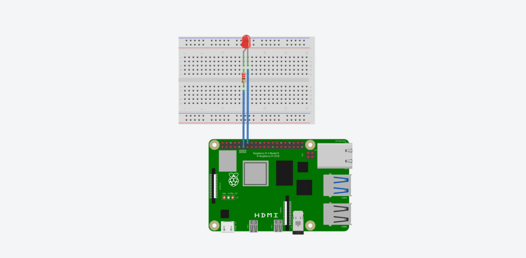
- Place the LED on the Breadboard: Insert the LED into the breadboard. LEDs have two legs: the longer leg (anode) is the positive side and the shorter leg (cathode) is the negative side.
- Connect the Resistor: Place one end of the 330-ohm resistor into the same row as the shorter leg of the LED (cathode). The resistor will limit the current flowing through the LED.
- Wire the Ground Connection:
- Use a jumper wire to connect the other end of the resistor to the ground rail (negative) on the breadboard.
- Then, use another jumper wire to connect the ground rail to a GND pin on the Raspberry Pi (e.g., physical pin 6).
- Wire the GPIO Output:
- Use a jumper wire to connect the longer leg of the LED (anode) to GPIO pin 17 on the Raspberry Pi (BCM numbering, physical pin 11).
Visual Summary of Connections:
- GPIO 17 (BCM) to LED anode (long leg).
- LED cathode (short leg) to resistor.
- Resistor to GND.
Double-Check Your Connections: Ensure all connections are secure and correct before powering on your Raspberry Pi. Incorrect wiring could damage the components or your Raspberry Pi.
Writing the Python Code to Blink the LED
With the circuit complete, it’s time to write the code that will control the LED. We’ll use Python, which is the recommended programming language for Raspberry Pi due to its simplicity and robust library support.
Step 1: Open the Python Environment
Raspberry Pi OS comes with Python pre-installed, along with the Thonny Python IDE, which is great for beginners. You can also use the Terminal to run your code directly.
- Open Thonny: Go to the main menu, navigate to “Programming,” and select “Thonny Python IDE.”
- Start a New File: Click “File” > “New” to create a new Python script.
Step 2: Import Required Libraries
The RPi.GPIO library is used to control the GPIO pins on the Raspberry Pi. This library provides functions to set up the pins, configure them as inputs or outputs, and control the state of the pins.
Python Code to Blink the LED:
import RPi.GPIO as GPIO
import time

# Set up GPIO using BCM numbering
GPIO.setmode(GPIO.BCM)

# Set up GPIO pin 17 as an output pin
GPIO.setup(17, GPIO.OUT)

try:
    while True:
        GPIO.output(17, GPIO.HIGH)  # Turn on the LED
        time.sleep(1)               # Wait for one second
        GPIO.output(17, GPIO.LOW)   # Turn off the LED
        time.sleep(1)               # Wait for one second
except KeyboardInterrupt:
    # Clean up GPIO settings on exit
GPIO.cleanup()Code Explanation:
import RPi.GPIO as GPIO: Imports the GPIO library and assigns it an alias for easier reference.import time: Imports the time module to use thesleep()function for delays.GPIO.setmode(GPIO.BCM): Sets the pin numbering system to BCM (Broadcom), which aligns with the GPIO pin numbers used in the code.GPIO.setup(17, GPIO.OUT): Configures GPIO pin 17 as an output.GPIO.output(17, GPIO.HIGH): Sends a high signal to pin 17, turning on the LED.time.sleep(1): Pauses the script for one second.GPIO.cleanup(): Resets the GPIO pins to their default state when the script is interrupted.
Step 3: Save and Run Your Code
- Save the Script: Click “File” > “Save As” and name your script, e.g.,
blink_led.py. - Run the Script: Click the green “Run” button or press
F5. The LED should start blinking on and off every second.
If everything is working correctly, congratulations—you’ve just completed your first Raspberry Pi project! This project not only introduces the basics of using GPIO pins but also provides a strong foundation for more complex electronics and coding tasks.
Troubleshooting Common Issues
If your LED isn’t blinking as expected, here are some common troubleshooting tips:
- Check Your Wiring: Double-check all connections, ensuring the LED, resistor, and jumper wires are placed correctly.
- Verify GPIO Pin Numbers: Ensure you’re using the correct GPIO pin numbers in the code. Remember that BCM numbering is different from the physical pin numbers.
- Test the Components: LEDs and resistors can sometimes be faulty. Swap them out with spares if you suspect a component isn’t working.
- Error Messages: If you encounter errors in the Terminal or IDE, carefully read the message. Common issues include typos in the code or missing libraries.
By mastering this simple project, you’ve taken the first step into the world of physical computing with Raspberry Pi. The skills you’ve learned here will serve as a strong foundation for tackling more advanced projects involving sensors, motors, and interactive devices.
Expanding the Blinking LED Project
Now that you’ve successfully created your first blinking LED project, it’s time to expand on what you’ve learned. Enhancing the basic project will deepen your understanding of how to control multiple components with the Raspberry Pi’s GPIO pins and allow you to explore more advanced programming concepts. Below are some ideas and steps to help you take your project to the next level.
Project Expansion 1: Adding a Second LED
Adding a second LED to your project allows you to explore controlling multiple outputs simultaneously. This expansion will introduce you to managing different GPIO pins independently, enabling you to create more complex patterns and light sequences.
Additional Components Needed:
- 1 x LED (any color)
- 1 x 330-ohm resistor
- Additional jumper wires
Wiring the Second LED:
- Place the Second LED: Insert the new LED into the breadboard, positioning it a few rows away from the first LED.
- Connect the Resistor: Attach one end of the 330-ohm resistor to the cathode (short leg) of the second LED, similar to the first setup.
- Wire the Ground: Connect the other end of the resistor to the ground rail on the breadboard.
- Wire GPIO Output: Use a jumper wire to connect the anode (long leg) of the second LED to GPIO pin 27 (BCM numbering, physical pin 13) on the Raspberry Pi.
Updated Python Code for Two LEDs:
import RPi.GPIO as GPIO
import time

# Set up GPIO using BCM numbering
GPIO.setmode(GPIO.BCM)

# Set up GPIO pins 17 and 27 as output pins
GPIO.setup(17, GPIO.OUT)
GPIO.setup(27, GPIO.OUT)

try:
    while True:
        GPIO.output(17, GPIO.HIGH)  # Turn on LED 1
        GPIO.output(27, GPIO.LOW)   # Turn off LED 2
        time.sleep(1)               # Wait for one second

        GPIO.output(17, GPIO.LOW)   # Turn off LED 1
        GPIO.output(27, GPIO.HIGH)  # Turn on LED 2
        time.sleep(1)               # Wait for one second
except KeyboardInterrupt:
GPIO.cleanup() # Clean up GPIO settings on exitCode Explanation:
GPIO.setup(27, GPIO.OUT): Sets up GPIO pin 27 as an output for the second LED.- Toggling LEDs: The code alternates between turning on and off each LED, creating a blinking sequence where one LED is on while the other is off.
Experiment with Different Patterns:
- Modify the timing with
time.sleep()to change the blinking speed. - Create new patterns by adjusting when each LED turns on or off.
Project Expansion 2: Controlling LEDs with a Button
Adding a push button to control the LEDs introduces interactivity to your project, teaching you how to read inputs from the GPIO pins. This step helps you understand how to create projects that respond to user input, such as switches, sensors, or other interactive components.
Additional Components Needed:
- 1 x Push Button
- 1 x 10k-ohm resistor
Wiring the Button:
- Place the Button on the Breadboard: Insert the push button into the breadboard so that it straddles the center gap.
- Connect One Side to Ground: Use a jumper wire to connect one side of the button to the ground rail on the breadboard.
- Connect the Other Side to GPIO: Connect the opposite side of the button to GPIO pin 22 (BCM numbering, physical pin 15).
- Add the Resistor: Place the 10k-ohm resistor between the GPIO pin and the ground rail. This resistor acts as a pull-down, ensuring the button reads LOW when not pressed.
Updated Python Code with Button Input:
import RPi.GPIO as GPIO
import time

# Set up GPIO using BCM numbering
GPIO.setmode(GPIO.BCM)

# Set up GPIO pins for LEDs and button
GPIO.setup(17, GPIO.OUT)  # LED 1
GPIO.setup(27, GPIO.OUT)  # LED 2
GPIO.setup(22, GPIO.IN, pull_up_down=GPIO.PUD_DOWN)  # Button with pull-down resistor

try:
    while True:
        # Check if the button is pressed
        if GPIO.input(22) == GPIO.HIGH:
            GPIO.output(17, GPIO.HIGH)  # Turn on LED 1
            GPIO.output(27, GPIO.LOW)   # Turn off LED 2
        else:
            GPIO.output(17, GPIO.LOW)   # Turn off LED 1
            GPIO.output(27, GPIO.HIGH)  # Turn on LED 2
        time.sleep(0.1)  # Short delay to debounce button presses
except KeyboardInterrupt:
GPIO.cleanup() # Clean up GPIO settings on exitCode Explanation:
GPIO.setup(22, GPIO.IN, pull_up_down=GPIO.PUD_DOWN): Configures GPIO pin 22 as an input with an internal pull-down resistor.- Button Control: The script reads the button’s state; when pressed, it toggles the LEDs.
Adding Button Functionality Enhancements:
- Experiment with longer or shorter button press timings to create different behaviors.
- Add multiple buttons for more complex input interactions, such as switching between different LED patterns.
Project Expansion 3: Adjusting LED Brightness with Pulse Width Modulation (PWM)
Pulse Width Modulation (PWM) is a technique used to adjust the brightness of LEDs or control the speed of motors by varying the amount of time the signal stays high within a given period. Implementing PWM will introduce you to more sophisticated control methods that are widely used in electronics.
Understanding PWM Basics:
- Duty Cycle: The percentage of time the signal is high during each cycle. A 50% duty cycle means the signal is high half the time, resulting in half brightness for an LED.
- Frequency: The rate at which the signal cycles on and off per second, measured in Hertz (Hz). For LED control, a frequency between 500Hz and 1kHz is typical.
Updated Python Code Using PWM:
import RPi.GPIO as GPIO
import time

# Set up GPIO using BCM numbering
GPIO.setmode(GPIO.BCM)

# Set up GPIO pin 17 as output and initialize PWM
GPIO.setup(17, GPIO.OUT)
led = GPIO.PWM(17, 1000)  # Set up PWM on pin 17 at 1kHz frequency
led.start(0)  # Start PWM with 0% duty cycle (off)

try:
    while True:
        # Gradually increase brightness
        for duty_cycle in range(0, 101, 5):  # Increase duty cycle from 0 to 100%
            led.ChangeDutyCycle(duty_cycle)
            time.sleep(0.1)
        # Gradually decrease brightness
        for duty_cycle in range(100, -1, -5):  # Decrease duty cycle from 100% to 0%
            led.ChangeDutyCycle(duty_cycle)
            time.sleep(0.1)
except KeyboardInterrupt:
    led.stop()        # Stop the PWM signal
GPIO.cleanup() # Clean up GPIO settingsCode Explanation:
GPIO.PWM(17, 1000): Initializes PWM on pin 17 with a frequency of 1kHz.led.ChangeDutyCycle(duty_cycle): Adjusts the duty cycle to change the LED brightness.- The loop gradually increases and then decreases the brightness, creating a smooth breathing effect.
Advanced PWM Ideas:
- Synchronize multiple LEDs to create dynamic lighting effects.
- Use input devices (like potentiometers or sensors) to control brightness interactively.
Project Expansion 4: Building a Traffic Light System
A traffic light system expands your skills further by combining multiple LEDs and incorporating logic control, timing, and sequencing. This project simulates the functionality of real-world traffic signals and teaches you to manage complex GPIO interactions.
Additional Components Needed:
- 1 x Red LED
- 1 x Yellow LED
- 1 x Green LED
- 3 x 330-ohm resistors
Wiring the Traffic Light System:
- Position the LEDs: Place the red, yellow, and green LEDs on the breadboard in a vertical line, similar to a traffic light layout.
- Connect Resistors: Attach a 330-ohm resistor to the cathode (short leg) of each LED.
- Connect Grounds: Wire the other end of each resistor to the ground rail on the breadboard.
- Wire GPIO Outputs:
- Red LED to GPIO pin 17 (BCM).
- Yellow LED to GPIO pin 27 (BCM).
- Green LED to GPIO pin 22 (BCM).
Python Code for Traffic Light Control:
import RPi.GPIO as GPIO
import time

# Set up GPIO using BCM numbering
GPIO.setmode(GPIO.BCM)

# Set up GPIO pins for red, yellow, and green LEDs
GPIO.setup(17, GPIO.OUT)  # Red LED
GPIO.setup(27, GPIO.OUT)  # Yellow LED
GPIO.setup(22, GPIO.OUT)  # Green LED

try:
    while True:
        # Green light on
        GPIO.output(22, GPIO.HIGH)
        time.sleep(5)

        # Yellow light on
        GPIO.output(22, GPIO.LOW)
        GPIO.output(27, GPIO.HIGH)
        time.sleep(2)

        # Red light on
        GPIO.output(27, GPIO.LOW)
        GPIO.output(17, GPIO.HIGH)
        time.sleep(5)

        # Yellow light before green
        GPIO.output(17, GPIO.LOW)
        GPIO.output(27, GPIO.HIGH)
        time.sleep(2)
        GPIO.output(27, GPIO.LOW)
except KeyboardInterrupt:
GPIO.cleanup() # Clean up GPIO settings on exitCode Explanation:
- The script cycles through the standard traffic light sequence: green, yellow, red, and back to yellow before returning to green.
- Each light is controlled independently using timed delays to simulate real-world operation.
Enhancing the Traffic Light Project:
- Add pedestrian crossing lights or sensors to detect cars or pedestrians.
- Use buttons to manually change light states, simulating traffic control systems.
Advanced Enhancements: Taking Your Blinking LED Project Further
Now that you’ve successfully implemented multiple expansions of the basic blinking LED project, you’re ready to explore even more advanced enhancements. These projects not only build upon the skills you’ve developed but also introduce new concepts such as sensors, real-time data collection, and integrating your Raspberry Pi with the web. These enhancements will help you transform your Raspberry Pi into a powerful tool for a wide range of real-world applications.
Project Expansion 5: Integrating Sensors to Control LED Behavior
Sensors add a whole new dimension to your Raspberry Pi projects by allowing your system to respond to environmental inputs. By integrating sensors, you can create projects that adjust LED behavior based on real-world data, such as light levels, temperature, or motion.
Example: Controlling an LED with a Light Sensor (Photoresistor)
A photoresistor (light-dependent resistor, or LDR) changes its resistance based on the amount of light it receives. By reading this data, you can program your Raspberry Pi to turn the LED on or off depending on the ambient light levels.
Additional Components Needed:
- 1 x Photoresistor (LDR)
- 1 x 10k-ohm resistor
- Additional jumper wires
Wiring the Light Sensor:
- Place the LDR on the Breadboard: Insert the LDR into the breadboard.
- Create a Voltage Divider: Connect one leg of the LDR to 3.3V on the Raspberry Pi. Connect the other leg to a GPIO pin (e.g., GPIO 18) through a 10k-ohm resistor, and also connect it to the ground.
- Connect the Output: The midpoint between the LDR and the resistor goes to GPIO pin 18 (BCM numbering).
Python Code to Control the LED with a Light Sensor:
import RPi.GPIO as GPIO
import time

# Set up GPIO using BCM numbering
GPIO.setmode(GPIO.BCM)

# Set up GPIO pins for LED and sensor
GPIO.setup(17, GPIO.OUT)  # LED
GPIO.setup(18, GPIO.IN)   # LDR input pin

try:
    while True:
        # Read sensor value
        sensor_value = GPIO.input(18)
        if sensor_value == GPIO.LOW:  # Adjust threshold based on your environment
            GPIO.output(17, GPIO.HIGH)  # Turn on the LED if the room is dark
        else:
            GPIO.output(17, GPIO.LOW)   # Turn off the LED if there is light
        time.sleep(0.1)
except KeyboardInterrupt:
GPIO.cleanup() # Clean up GPIO settings on exitCode Explanation:
- The script reads the state of the LDR and toggles the LED based on ambient light conditions.
- This project teaches the fundamentals of analog-to-digital conversion using simple voltage dividers and digital GPIO input.
Further Enhancements:
- Integrate multiple sensors to create a smart lighting system that responds to both motion and light levels.
- Use more precise sensors, like the TSL2561 digital light sensor, to improve accuracy.
Project Expansion 6: Creating an Internet-Connected LED
Connecting your Raspberry Pi to the internet opens up a vast range of possibilities, including remote control, real-time data visualization, and integration with cloud services. By connecting your LED project to the web, you can control it from anywhere or use web data to trigger actions.
Example: Controlling an LED with a Web Interface
You can create a basic web server using Flask (a lightweight Python web framework) to control your LED from any device on your network. This project demonstrates the basics of web development and introduces concepts like HTTP requests and server-client communication.
Installing Flask on Your Raspberry Pi:
- Update and Install Flask:
sudo apt update
sudo apt install python3-flaskPython Code for a Simple Flask Web Server:
from flask import Flask, render_template, request
import RPi.GPIO as GPIO

# Set up GPIO using BCM numbering
GPIO.setmode(GPIO.BCM)
GPIO.setup(17, GPIO.OUT)  # LED pin

# Create a Flask web app
app = Flask(__name__)

# Default route to control the LED
@app.route("/")
def index():
    return render_template("index.html")  # Simple HTML file with on/off buttons

# Route to handle LED control
@app.route("/<action>")
def action(action):
    if action == "on":
        GPIO.output(17, GPIO.HIGH)
    elif action == "off":
        GPIO.output(17, GPIO.LOW)
    return f"LED is now {action}"

if __name__ == "__main__":
    try:
        app.run(host="0.0.0.0", port=5000)  # Run on local network
    except KeyboardInterrupt:
GPIO.cleanup()Creating the HTML Interface (index.html):
Create a file named index.html in the same directory as your Python script with the following content:
<!DOCTYPE html>
<html lang="en">
<head>
    <meta charset="UTF-8">
    <title>LED Control</title>
</head>
<body>
    <h1>Control the LED</h1>
    <a href="/on">Turn On</a>
    <a href="/off">Turn Off</a>
</body>
</html>Running the Web Server:
- Save both the Python script and HTML file in the same folder.
- Run the Python script using
python3 your_script_name.py. - Access the web server by entering
http://<your-raspberry-pi-ip>:5000in your browser.
Code Explanation:
- The Flask server listens for requests to turn the LED on or off based on the URL endpoint.
- This project shows how to interact with hardware through web interfaces, a foundational skill for IoT development.
Advanced Web Control Ideas:
- Secure your web interface with password protection or OAuth for more secure remote access.
- Add real-time feedback by displaying the LED’s current state or integrating sensors to display additional data.
Project Expansion 7: Logging Data with Your Raspberry Pi
Data logging is a critical component of many real-world applications, such as environmental monitoring, research projects, and automation systems. Expanding your LED project to include data logging teaches you how to collect, store, and analyze data from sensors or other inputs.
Example: Logging LED Activity to a File
By logging when the LED turns on or off, you can track system behavior over time. This can be especially useful in monitoring systems or when debugging more complex interactions.
Updated Python Code for Logging:
import RPi.GPIO as GPIO
import time

# Set up GPIO using BCM numbering
GPIO.setmode(GPIO.BCM)
GPIO.setup(17, GPIO.OUT)  # LED pin

# Open a log file in append mode
log_file = open("led_log.txt", "a")

try:
    while True:
        GPIO.output(17, GPIO.HIGH)  # Turn on LED
        log_file.write(f"{time.ctime()}: LED ON\n")
        log_file.flush()  # Ensure data is written to the file
        time.sleep(1)

        GPIO.output(17, GPIO.LOW)  # Turn off LED
        log_file.write(f"{time.ctime()}: LED OFF\n")
        log_file.flush()
        time.sleep(1)
except KeyboardInterrupt:
    GPIO.cleanup()
log_file.close() # Close the log fileCode Explanation:
- The script writes the time and action (LED on or off) to a text file, creating a simple activity log.
- This project introduces file handling in Python and the concept of logging data for later analysis.
Advanced Data Logging Ideas:
- Use Python libraries like Pandas to process and analyze the logged data, providing insights into system performance or behavior patterns.
- Expand to cloud logging by integrating services like AWS IoT Core, Google Cloud IoT, or ThingSpeak to visualize data in real time.
Project Expansion 8: Automating LED Control with Sensors and Timers
Combining multiple sensors, timers, and logic control allows you to automate your LED behavior without manual input. Automation is key in many applications, from smart home systems to industrial monitoring.
Example: LED Control Based on Ambient Light and Time
Create a system where the LED automatically turns on when it’s dark and stays off during daylight hours, combining light sensing and time-based control.
Updated Python Code with Automation:
import RPi.GPIO as GPIO
import time
from datetime import datetime

# Set up GPIO using BCM numbering
GPIO.setmode(GPIO.BCM)
GPIO.setup(17, GPIO.OUT)  # LED
GPIO.setup(18, GPIO.IN)   # Light sensor (LDR)

# Define time range for LED operation (e.g., 6 PM to 6 AM)
def is_nighttime():
    current_time = datetime.now().time()
    return current_time >= datetime.strptime("18:00", "%H:%M").time() or \
           current_time <= datetime.strptime("06:00", "%H:%M").time()

try:
    while True:
        # Check light level and time
        if GPIO.input(18) == GPIO.LOW and is_nighttime():
            GPIO.output(17, GPIO.HIGH)  # Turn on LED
        else:
            GPIO.output(17, GPIO.LOW)   # Turn off LED
        time.sleep(0.5)
except KeyboardInterrupt:
GPIO.cleanup()Code Explanation:
- The code checks if it’s nighttime and whether the light level is low before turning on the LED, demonstrating conditional control using time and sensor data.
- This project integrates software control with real-world conditions, enhancing the automation capabilities of your system.
Expanding Automation Projects:
- Integrate with other smart home devices like smart plugs, blinds, or HVAC systems for more complex automation scenarios.
- Use sensors like motion detectors, temperature probes, or humidity sensors to trigger additional actions.
Conclusion
Creating a simple blinking LED project with the Raspberry Pi is a great starting point for anyone new to electronics and programming. Through various expansions and enhancements, you can transform this basic project into a sophisticated, interactive system that responds to inputs, automates tasks, and connects to the web. These skills lay the groundwork for tackling more advanced projects, from building IoT devices to designing complex automation systems.
As you continue to experiment and explore, remember that each project builds on the skills you’ve developed. Don’t hesitate to try new things, modify existing setups, and push the boundaries of what your Raspberry Pi can do. With a combination of creativity, coding, and curiosity, the possibilities are virtually endless.